EP0935197A2 - Integrierte Schaltung mit eingebettetem Emulator und Emulationsvorrichtung dafür - Google Patents
Integrierte Schaltung mit eingebettetem Emulator und Emulationsvorrichtung dafür Download PDFInfo
- Publication number
- EP0935197A2 EP0935197A2 EP99650010A EP99650010A EP0935197A2 EP 0935197 A2 EP0935197 A2 EP 0935197A2 EP 99650010 A EP99650010 A EP 99650010A EP 99650010 A EP99650010 A EP 99650010A EP 0935197 A2 EP0935197 A2 EP 0935197A2
- Authority
- EP
- European Patent Office
- Prior art keywords
- data processor
- development system
- emulation
- target data
- target
- Prior art date
- Legal status (The legal status is an assumption and is not a legal conclusion. Google has not performed a legal analysis and makes no representation as to the accuracy of the status listed.)
- Withdrawn
Links
Images


Classifications
-
- G—PHYSICS
- G06—COMPUTING OR CALCULATING; COUNTING
- G06F—ELECTRIC DIGITAL DATA PROCESSING
- G06F11/00—Error detection; Error correction; Monitoring
- G06F11/36—Prevention of errors by analysis, debugging or testing of software
- G06F11/362—Debugging of software
- G06F11/3648—Debugging of software using additional hardware
- G06F11/3656—Debugging of software using additional hardware using a specific debug interface
-
- G—PHYSICS
- G06—COMPUTING OR CALCULATING; COUNTING
- G06F—ELECTRIC DIGITAL DATA PROCESSING
- G06F11/00—Error detection; Error correction; Monitoring
- G06F11/22—Detection or location of defective computer hardware by testing during standby operation or during idle time, e.g. start-up testing
- G06F11/26—Functional testing
- G06F11/261—Functional testing by simulating additional hardware, e.g. fault simulation
Definitions
- the present invention relates to an integrated circuit having an emulator embedded therein, and to an emulation system for use with such an integrated circuit.
- Executable code for a data processor requires testing and correction during its development cycle.
- Software debugging is initially done in a simulator or debugger offline. Once the software is debugged, it is then down loaded into the target system. However, if the software does not work correctly, for example, due to a timing problem it is then necessary to do an "in circuit” examination of the software and the data that it is manipulating. It is known to perform this by removing the target data processor and replacing it with a replica of the data processor which can be probed or interrogated via an emulation pod. The replica data processor emulates the real data processor and this process is called "in circuit emulation".
- a disadvantage of known "in circuit” emulators is that the additional sockets, clips, adaptors or pods can induce extra parasitic components into the target system which alter its performance. This usually restricts the emulation to a slow speed in order to avoid timing problems introduced by the parasitic components.
- the use of such in circuit emulators can cause problems where debugging is to be performed in hybrid digital-analogue systems where analogue accuracy is a critical issue, especially when more than 6 or 7 bit resolution of analogue variables is used.
- a data processor including an emulator, wherein the emulator is arranged to communicate with an external device via a single terminal.
- bi-directional communication is performed via the single terminal.
- said single terminal is a control pin of said data processor, said pin only controlling said data processor during a predetermined operation.
- said predetermined operation is an initialisation sequence.
- a development system for use with a target data processor including an emulator, wherein bi-directional communication between said development system and the data processor occurs via a serial data link utilising a single pin of the data processor, said development system comprising a control data processor and at least one interface element for providing an interface between the control data processor and the target data processor.
- said at least one interface element provides electrical isolation between the target data processor and the control data processor.
- the at least one interface element contains means for causing a transition on the data link in order to cause the target data processor to enter an emulation mode.
- said transition causing means is controllable to transmit instructions to the target data processor.
- the development system further comprises a plurality of interface elements, wherein each interface element is individually addressable by the control data processor.
- bi-directional communication between the at least one interface element and the control data processor is via a radiative data link
- the radiative data link may be an infra-red data link.
- the status and register contents of the target data processor are retrieved and stored during emulation.
- the status and register contents of the target data processor are returned to the target data processor before recommencing execution of a user program.
- the status and register contents of the target data processor are stored in an associated interface element.
- the development system is arranged to read a block of program code from the data processor, to modify the program code and to re-present the modified code to the target data processor.
- the program code is modified by the insertion of a break point instruction at a chosen location.
- the interface element automatically detects the data transmission rate of an associated target data processor operating in an emulation mode.
- the interface element performs handshaking and data exchange with the target data processor.
- the interface element performs handshaking and data exchange with the control data processor.
- the interface element moves control and data information between the target and control data processors.
- the interface element communicates with the target data processor via a serial communications link.
- the serial communications link utilises a pin of a data processor.
- the development system is arranged to communicate with a target data processor such that the target data processor such that the target data processor can be programmed in situ.
- the programming is performed using the serial communications link.
- the development system can modify programme instructions and data within the target data processor.
- data includes calibration coefficients.
- the development system interfaces simultaneously with a plurality of target data processors.
- the development system is arranged to retrieve data from at least one target data processor and display the data in a graphical form, for example, the graphical form is an oscilloscope trace.
- the development system is arranged to retrieve data from the at least one target data processor and to perform frequency domain analysis of the data.
- the invention provides an interface card for performing serial communication with a target data processor and for communicating with a emulation control data processor.
- the invention provides a development system wherein the interface card is left connected to the target data processor and communicates with the control data processor via a radiative communications link
- a data processor including an emulation controller for causing the data processor to enter an emulation mode, and dedicated registers for use in the emulation mode.
- a software driven emulator within a data processor which leaves the registers used by the data processor to execute tasks unaltered during an emulation or debug operation.
- a software driven emulator is flexible and allows, for practical purposes, for an unlimited number of break points to be implemented.
- registers dedicated for use by a data processing core (also known as an arithmetic logic unit) of the data processor during emulation can only be altered during emulation.
- a programme for controlling the operation of the data processing core during emulation is stored in a reserved non-volatile memory area which is hidden from the user of the data processor.
- the emulation controller can operate in a single step mode wherein the register status of the data processor, or other information such as the contents of a stack or memory can be output after executing a single instruction of the user's programme.
- the emulation controller is responsive to a single byte instruction placed in the user code in order to initiate the emulation mode.
- the single byte instruction is, in general written over another instruction in the user's programme.
- the overwritten instruction is held in a special purpose register so that it is executed when the emulation mode is exited.
- the data processor may also be responsive to a signal on one of the data processor control pins in order to initiate the emulation mode.
- a data processor having an emulator embedded therein, and in which the emulator is initiated by a single word instruction.
- a data processor including an emulator therein arranged to communicate information concerning the internal status of the data processor via a serial communication link.
- the serial data link utilises a pin in the data processor package.
- the pin is multiplexed with a control function of the data processor.
- some data processors include control pins which are only relevant during the power up initialisation of the data processor.
- the pin may indicate to the processor whether it is to initially execute instructions from an internal or an external memory. Once this information has been conveyed to the processing core of the data processor the pin becomes effectively redundant.
- Such a pin may then be used as a communication link between the embedded emulation system within the data processor and an external development system or emulator controller.
- the emulator is responsive to a signal on the pin, such as a voltage transition, in order to activate the emulator.
- the emulator is a software controlled emulator, and comprises emulation instructions held as software within a reserved memory integrated into the data processor.
- the receipt of the instruction to start emulation either by a signal on the emulator control pin or via a software instruction within the software being debugged, forces the data processing core of the data processor to suspend execution of the user's programming code and to execute instructions from the emulation instruction code.
- the receipt of an instruction to commence emulation causes a high level non maskable interrupt to be issued to the data processing core of the data processor.
- the data processor executes emulation instructions using reserved emulation registers, thereby leaving the contents of the registers used for programme code execution unaltered, except possibly for the programme address controller and the stack which may experience some minor and wholly reversible alterations.
- an auxiliary stack and/or auxiliary programme address counters may also be provided solely for use within the emulation routine such that the registers, programme counter and stack used by user executable code may be left entirely unaltered.
- dedicated registers may also be provided for storing the contents of the program address controller.
- the data processor may be arranged to down load the stack and register contents to virtual registers with an emulator control data processor or within an interface element, and to up load the register and stack contents when exiting the emulation mode.
- a development system comprising a control data processor for monitoring the status of a target data processor, wherein the target data processor includes an embedded emulator for communicating information concerning the internal status of the target data processor via a serial communications link, the development system including interface element adapted to communicate via the serial communications link.
- the interface element may be in the form of a pod providing electrical isolation between the target and control data processor.
- the pod provides bi-directional communication between the target and control data processors and includes a controllable voltage generator for causing a voltage transient on an emulation control pin of the target data processor for forcing it to enter the emulation mode.
- the voltage generator may also be used to communicate data and instructions to the target data processor.
- the interface element communicates with the control data processor via a conductive link, such as a cable.
- the communications pod may communicate with the control data processor over a radio or optical based, such as infra-red, communications link.
- the or each communications pod has a unique identity such that a plurality of pods may be independently addressed by a single emulation control data processor.
- the emulation control data processor can control and/or debug a plurality of target data processors within a target system.
- each interface element contains a local data processor for handling any timing features or handshaking required to communicate over the data link.
- the local data processor may contain registers or memory for temporarily storing the register contents of an associated target data processor, or may handle the modification of a block user program code, ie changing the code or inserting a break point instruction.
- the or each interface element is a pod having three pins, one for connection to ground, one for connection to the power rail Vcc, and one for connection to the pin on the target data processor for communication therewith.
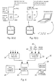
- FIG. 1 schematically illustrates a prior art emulator in which a large emulation pod plugs into the data processor socket on a customer's target board in order to provide interconnection with an emulator system comprising an emulation control processor running an emulator software package which typically displays register contents of the target processor and allows for editing of instructions via a graphical user interface (GUI).
- GUI graphical user interface
- the large size of the emulation pod makes it inconvenient to use and also can give rise to subtle changes in operation of the target board due to the extra load and parasitic components introduced by the emulation pod.
- the known emulation pod uses a different or modified data processor which gives rise to changes in output driver characteristics and loadings which can effect signal timings and degrade analogue performance where analogue circuits or DAC or ADC's are involved.
- an emulation system comprising a data processor constituting an embodiment of the present invention and an interface card 3 for providing galvanic isolation between the customer's target board and the emulation control data processor 2 provides for a more compact emulation system and, more importantly does not change the operating characteristics of the customer's target board due to the introduction of parasitic components.
- the data processor having an emulator according to the present invention performs emulation under software control.
- a reserved memory containing emulation instructions is provided as an integral part of the data processor.
- a data processor may have, for example, a memory space in which addresses 0000H to 1FFFH (where "H" indicates that the addresses are expressed in hexadecimal) are provided for internal user programme code and the addresses 2000H to FFFFH are allocated to external user code space.
- the emulation memory is placed on another page of memory such that it remains hidden from the user.
- external memory addresses F900H to FFFFH may contain a user programme
- internal addresses F900H and above contain the emulation programme.
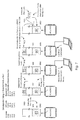
- Figure 4 schematically illustrates the internal arrangement of a data processor, generally illustrated as 20, whereby a programme address controller 22 holds the address of the next memory location to be read from.
- This location normally points to a boot strap memory 24 which contains executable code to be used during power up sequences or for data exchange routines, or to a user programme 26 which may be stored in an internal user code memory 28 or in external memory (not shown).
- the programme address controller 22 is responsive to an interrupt request handler 30 which, as is well known in the art, allows normal execution of a programme to be interrupted in order to respond in a predetermined way to specific events.
- the data processor is arranged to execute an interrupt routine in response to an interrupt request and then to return to the user code when the interrupt routine has been completed.
- the data processor constituting an embodiment of the present invention is also provided with an emulation request controller 32 which issues a priority non- maskable interrupt request which takes precedence over all other interrupt functions.
- the interrupt controller 30 is arranged to buffer incoming interrupts while the programme address controller is responsive to the emulation request controller 32 in order to ensure that interrupt requests are properly serviced upon return from the emulation mode.
- the emulation request controller is responsive to three inputs.
- a first input is responsive to a voltage transition on a single pin of the data processor package.
- the state of the pin is latched by the data processor at power up or reset and thereafter it can be used as the emulation control pin.
- the EA pin is also used, when emulation has been initiated, as a bi-directional serial communications pin.
- the emulation request controller is also responsive to a single step flag 42 which ensures that an emulation request occurs after execution of a single instruction of the user programme code.
- the emulation controller 32 is responsive to a break point instruction whose occurrence in the user code causes the emulation controller 32 to issue an emulation request.
- a break point instruction decoder 50 is provided to specifically handle the occurrence of the additional single byte emulation instruction (break point instruction) contained within user programme memory 52, which may be external memory or, more likely, internal memory area 28. Additionally, a special register EMU2 is provided to hold the instruction which was overwritten by the emulation request instruction thereby ensuring that the addresses of the remaining programme code are unaltered.
- the data processing core 54 also known as an arithmetic logic unit ALU
- the reserved register set may also include an alternative stack and/or programme counter for use during emulation.
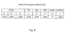
- Figure 8 illustrates the emulation control register, EMUCON, provided within a data processor including an embedded software controlled emulator.
- EMUCON emulation control register
- the first three bits of the register form a control word which causes internal timers and clocks of the data processor to be disabled if the correct code, in this example 101, is written into these bits of this special function register.
- the fourth bit is an emulation enable bit, EE, which is placed in the enable condition by default and enables emulation to be started when an appropriate emulation request is received by the emulation request controller.
- the fifth bit enables execution of the contents of the special function register EMU2.
- this EES register is inspected in order to determine whether the break point instruction should actually be executed. If the contents of this register are not set, then the emulation will be performed.
- the address pointer points to the address of the break point. As mentioned earlier, the original instruction which was overwritten by the break point is loaded into the EMU2 special function register and the bit EES is cleared. As the emulation programme returns control to user code, it sets the EES bit. The address programme counter will return control at the address of the break point instruction.
- the EES bit is set and instead of re-executing the emulation routine, the processing core of the data processor is caused to execute the instruction held in the EMU2 special function register.
- the EES bit is then toggled once the instruction in the EMU2 register is executed, thereby ensuring that the next occurrence of the break point instruction will cause the emulation routine to be re-entered.
- the sixth bit is an emulation single step, ESS bit which causes the data processor to only execute single instructions between emulator programme operations.
- the final two bits EA-in and EA-out enable the status of the EA pin to be read and written to respectively.
- FIGS 6a to 6d schematically illustrate operation of the emulator in a single step code execution mode.
- the emulation routine takes advantage of the fact that the emulation interrupt will not respond until at least one instruction of the user code has been executed.
- the emulator issues, via a hardware resource, a highest priority non-maskable interrupt that ensures that programme execution is immediately returned to the emulator, irrespective of what instruction was being performed.
- the emulation control data processor is arranged to issue an emulation request via the EA pin which causes a jump to the emulation memory.
- This initially allows communication between the emulation control data processor 2 and the emulator in order that new instructions can be set in the emulator, such as changing one or more of the flags in the EMUCON register, in this example, the control data processor sets the single step instruction, ESS, flag in the EMUCON register.
- the emulation control data processor has indicated that it does not wish to set any further instruction changes, control is relinquished from the emulation code and the user code is executed.
- the EMUCON register was set with the single step enabled, and interrupt request is issued via the emulation controller 32 thereby causing control to be returned to the emulation code after a single instruction of the user code has been executed as shown in Figure 6c.
- the emulation code then down loads data to the emulation control data processor 2 via the EA pin. Down loaded data may include the status of the internal registers of the data processor, but may also, depending on instructions received from the emulation control data processor, include the contents of the stack and also the contents of selected areas of internal or external memory, or the contents of an internal cache.
- Figure 7 illustrates an example of an emulation request initiated via the break point instruction.
- the data processor has a data processing core supporting the 8051 instruction set.
- the 8051 instruction set has a unused instruction code of A5.
- the A5 instruction has been implemented as the break point instruction.
- the interface element 3 may provide a local buffer such that as the block of program code (usually two rows on the internal non-volatile reprogrammable user code memory of the data processor), is buffered in the interface element and the local data processor modifies the data to change instructions or insert the break point, and then represents the data to the target data processor in order that it can rewrite the data into it's internal memory.
- the programme counter During execution of the user programme, the programme counter will eventually point to the address 0120 which has the A5 emulation break point instruction written therein in place of the "clear A" instruction.
- the instruction decoder of the data processor decodes the break point instruction and causes the emulation request controller 32 to issue a priority interrupt.
- the data processing core 54 discontinues execution of the user's programme and starts executing instructions from the emulation memory provided that the EES bit in the EMUCON register cleared. Assuming that the EES bit is cleared, the data processing core executes the emulation instructions using the reserved EMU1 register, and outputs data concerning the status of the various programme registers to the emulation data processor 2.
- the emulation data processor toggles the EES bit and issues a command causing the emulation to continue.
- the emulator then returns control to the user programme. Because the break point instruction is interrupt driven, the control is returned to address 0120 which holds the A5 break point instruction. This time the EES bit indicates that emulation should not be recommenced, but in fact that the instruction in the EMU2 register should be executed.
- the data processing core executes the instruction in the EMU2 register and returns control to the user programme at the address following the break point instruction.
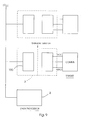
- Figure 9 schematically illustrates a multi-target development system in which a single control data processor 2 communicates with a plurality of target data processors via a plurality of interface elements 3, each of which contain a local data processor 100 which reduces the computational load on the control data processor by performing the communications protocols and also buffers and modified data in the target data processors in response to commands from the emulation control data processor 2.
- a data processor having a software driven emulator embedded therein which uses dedicated registers, thereby ensuring that registers used in execution of a user's programme do not become altered once the emulation mode is commenced. It is also possible to provide a development system for use with such a microprocessor in order that the internal registers may be inspected, or blocks of memory may be inspected and analysis performed thereon. For example, a block of memory may hold values resulting from analogue to digital conversions. The values may be displayed by the emulation control data processor in order to form an oscilloscope trace of the analogue value, or additionally or alternatively may be Fourier transformed in order to perform frequency domain analysis.
- the emulator may be used to perform a software controlled series of Analogue to Digital conversions, and to send these to the emulator control processor which can then display a graph or trace of the converted variable.
- the emulator 2 may display a plurality of windows, with each displaying the status of and/or controlling the function of a respective target data processor within a multi-processor target board.
- master and slave processors may be analysed, possibly on a single step basis, in order to check their data exchange operations and mutual performance.
- the emulator has authority to modify the internal memory contents of program and data memory within the target data processor.
- the target data processor may be re-programmed whilst it is in situ in the target board.
- calibration coefficients in digital or hybrid digital-analogue systems can be modified.
- the interface element communicates using a radiative link, to leave the interface element attached to the target board permanently, thereby allowing for the target data processor to be re-programmed even after it has been installed in a working environment.
- the provision of an emulator as an integral part of the target data processor has the additional advantage that the board and processor being debugged/developed are identical to the final system.
Landscapes
- Engineering & Computer Science (AREA)
- Computer Hardware Design (AREA)
- Theoretical Computer Science (AREA)
- General Engineering & Computer Science (AREA)
- Quality & Reliability (AREA)
- Physics & Mathematics (AREA)
- General Physics & Mathematics (AREA)
- Test And Diagnosis Of Digital Computers (AREA)
- Debugging And Monitoring (AREA)
Applications Claiming Priority (2)
| Application Number | Priority Date | Filing Date | Title |
|---|---|---|---|
| US09/019,789 US6230119B1 (en) | 1998-02-06 | 1998-02-06 | Integrated circuit with embedded emulator and emulation system for use with such an integrated circuit |
| US19789 | 1998-02-06 |
Publications (2)
| Publication Number | Publication Date |
|---|---|
| EP0935197A2 true EP0935197A2 (de) | 1999-08-11 |
| EP0935197A3 EP0935197A3 (de) | 1999-09-22 |
Family
ID=21795026
Family Applications (1)
| Application Number | Title | Priority Date | Filing Date |
|---|---|---|---|
| EP99650010A Withdrawn EP0935197A3 (de) | 1998-02-06 | 1999-02-05 | Integrierte Schaltung mit eingebettetem Emulator und Emulationsvorrichtung dafür |
Country Status (3)
| Country | Link |
|---|---|
| US (1) | US6230119B1 (de) |
| EP (1) | EP0935197A3 (de) |
| IE (1) | IES990080A2 (de) |
Cited By (3)
| Publication number | Priority date | Publication date | Assignee | Title |
|---|---|---|---|---|
| EP1531392A1 (de) * | 2003-10-31 | 2005-05-18 | P21 - Power for the 21st Century GmbH | Verfahren zum Steuern und/oder Regeln wenigstens einer Komponente in einem technischen System und/oder in einem technischen Prozess sowie technisches System |
| EP1280061A3 (de) * | 2001-07-25 | 2007-03-28 | Electronics and Telecommunications Research Institute | Vorrichtung und Verfahren zur Querentwicklung durch drahtlose Kommunikation |
| US9652260B2 (en) | 2013-12-04 | 2017-05-16 | International Business Machines Corporation | Scriptable hierarchical emulation engine |
Families Citing this family (33)
| Publication number | Priority date | Publication date | Assignee | Title |
|---|---|---|---|---|
| JPH08263438A (ja) * | 1994-11-23 | 1996-10-11 | Xerox Corp | ディジタルワークの配給及び使用制御システム並びにディジタルワークへのアクセス制御方法 |
| EP0935195A2 (de) | 1998-02-06 | 1999-08-11 | Analog Devices, Inc. | Integrierte Schaltung mit hochauflösendem Analog-Digital-Wandler, einem Mikrokontroller und hochdichtem Speicher und einem Emulator dafür |
| US6567933B1 (en) * | 1999-02-19 | 2003-05-20 | Texas Instruments Incorporated | Emulation suspension mode with stop mode extension |
| WO2001016702A1 (en) | 1999-09-01 | 2001-03-08 | Intel Corporation | Register set used in multithreaded parallel processor architecture |
| HK1046049A1 (zh) | 1999-09-01 | 2002-12-20 | Intel Corporation | 用於多线程处理器的分支指令 |
| GB2362730B (en) * | 1999-12-23 | 2004-02-11 | St Microelectronics Sa | Computer register watch |
| US6978233B1 (en) * | 2000-03-03 | 2005-12-20 | Unisys Corporation | Method for emulating multi-processor environment |
| US7681018B2 (en) | 2000-08-31 | 2010-03-16 | Intel Corporation | Method and apparatus for providing large register address space while maximizing cycletime performance for a multi-threaded register file set |
| US6886110B2 (en) * | 2000-11-21 | 2005-04-26 | Wind River Systems, Inc. | Multiple device scan chain emulation/debugging |
| US7020871B2 (en) * | 2000-12-21 | 2006-03-28 | Intel Corporation | Breakpoint method for parallel hardware threads in multithreaded processor |
| US7072824B2 (en) * | 2001-05-09 | 2006-07-04 | Lucent Technologies Inc. | Method and apparatus for emulating a processor |
| US7216204B2 (en) | 2001-08-27 | 2007-05-08 | Intel Corporation | Mechanism for providing early coherency detection to enable high performance memory updates in a latency sensitive multithreaded environment |
| US6868476B2 (en) | 2001-08-27 | 2005-03-15 | Intel Corporation | Software controlled content addressable memory in a general purpose execution datapath |
| US7225281B2 (en) * | 2001-08-27 | 2007-05-29 | Intel Corporation | Multiprocessor infrastructure for providing flexible bandwidth allocation via multiple instantiations of separate data buses, control buses and support mechanisms |
| US7487505B2 (en) * | 2001-08-27 | 2009-02-03 | Intel Corporation | Multithreaded microprocessor with register allocation based on number of active threads |
| US6545501B1 (en) | 2001-12-10 | 2003-04-08 | International Business Machines Corporation | Method and system for use of a field programmable function within a standard cell chip for repair of logic circuits |
| US6668361B2 (en) | 2001-12-10 | 2003-12-23 | International Business Machines Corporation | Method and system for use of a field programmable function within a chip to enable configurable I/O signal timing characteristics |
| US6754881B2 (en) | 2001-12-10 | 2004-06-22 | International Business Machines Corporation | Field programmable network processor and method for customizing a network processor |
| US7047464B2 (en) * | 2001-12-10 | 2006-05-16 | International Business Machines Corporation | Method and system for use of a field programmable function within an application specific integrated circuit (ASIC) to access internal signals for external observation and control |
| US7610451B2 (en) * | 2002-01-25 | 2009-10-27 | Intel Corporation | Data transfer mechanism using unidirectional pull bus and push bus |
| US20030225567A1 (en) * | 2002-03-09 | 2003-12-04 | Koch Stefan Marco | System and method for emulating an embedded non-volatile memory |
| US7437724B2 (en) | 2002-04-03 | 2008-10-14 | Intel Corporation | Registers for data transfers |
| US7337275B2 (en) * | 2002-08-13 | 2008-02-26 | Intel Corporation | Free list and ring data structure management |
| US6941438B2 (en) | 2003-01-10 | 2005-09-06 | Intel Corporation | Memory interleaving |
| US7480786B1 (en) * | 2003-04-16 | 2009-01-20 | Xilinx, Inc. | Methods and cores using existing PLD processors to emulate processors having different instruction sets and bus protocols |
| EP1864219A1 (de) * | 2006-02-28 | 2007-12-12 | Mentor Graphics Corporation | Übrwachung physischer parameter in einer emulationsumgebung |
| US8131840B1 (en) | 2006-09-12 | 2012-03-06 | Packet Plus, Inc. | Systems and methods for data stream analysis using embedded design logic |
| US7983893B2 (en) * | 2008-01-08 | 2011-07-19 | Mentor Graphics Corporation | Fault support in an emulation environment |
| US20090182544A1 (en) * | 2008-01-15 | 2009-07-16 | Eric Durand | Multiple chassis emulation environment |
| US7930165B2 (en) * | 2008-02-07 | 2011-04-19 | Accemic Gmbh & Co. Kg | Procedure and device for emulating a programmable unit providing system integrity control |
| US8214192B2 (en) | 2008-02-27 | 2012-07-03 | Mentor Graphics Corporation | Resource remapping in a hardware emulation environment |
| US8214195B2 (en) * | 2008-03-21 | 2012-07-03 | Mentor Graphics Corporation | Testing in a hardware emulation environment |
| US20090248390A1 (en) * | 2008-03-31 | 2009-10-01 | Eric Durand | Trace debugging in a hardware emulation environment |
Family Cites Families (14)
| Publication number | Priority date | Publication date | Assignee | Title |
|---|---|---|---|---|
| US4272760A (en) * | 1979-04-10 | 1981-06-09 | Burr-Brown Research Corporation | Self-calibrating digital to analog conversion system and method |
| US4860289A (en) * | 1987-10-19 | 1989-08-22 | John Fluke Mfg. Co., Inc. | Reset circuit for electrically isolated circuits communicating via uart |
| GB2235076B (en) * | 1989-08-17 | 1994-05-04 | Asahi Optical Co Ltd | Camera data communication method and camera |
| US5375228A (en) * | 1991-02-04 | 1994-12-20 | Analog Devices, Inc. | Real-time signal analysis apparatus and method for digital signal processor emulation |
| US5321828A (en) * | 1991-06-07 | 1994-06-14 | Step Engineering | High speed microcomputer in-circuit emulator |
| GB2266606B (en) * | 1992-04-27 | 1996-02-14 | Intel Corp | A microprocessor with an external command mode |
| US5313618A (en) * | 1992-09-03 | 1994-05-17 | Metalink Corp. | Shared bus in-circuit emulator system and method |
| US5758059A (en) * | 1992-12-03 | 1998-05-26 | Intel Corporation | In-circuit emulator in which abrupt and deferred arming and disarming of several events on a microprocessor chip are controlled using a single-input pin |
| US5488688A (en) * | 1994-03-30 | 1996-01-30 | Motorola, Inc. | Data processor with real-time diagnostic capability |
| US5699554A (en) * | 1994-10-27 | 1997-12-16 | Texas Instruments Incorporated | Apparatus for selective operation without optional circuitry |
| JP3443694B2 (ja) * | 1994-11-01 | 2003-09-08 | 日本テキサス・インスツルメンツ株式会社 | エミュレーション時のレジスタモニタ方法 |
| CN1279449C (zh) * | 1994-12-28 | 2006-10-11 | 株式会社东芝 | 微处理器 |
| US5752077A (en) * | 1995-05-15 | 1998-05-12 | Motorola, Inc. | Data processing system having a multi-function input/output port with individual pull-up and pull-down control |
| US5544311A (en) * | 1995-09-11 | 1996-08-06 | Rockwell International Corporation | On-chip debug port |
-
1998
- 1998-02-06 US US09/019,789 patent/US6230119B1/en not_active Expired - Lifetime
-
1999
- 1999-02-05 IE IE990080A patent/IES990080A2/en not_active IP Right Cessation
- 1999-02-05 EP EP99650010A patent/EP0935197A3/de not_active Withdrawn
Cited By (3)
| Publication number | Priority date | Publication date | Assignee | Title |
|---|---|---|---|---|
| EP1280061A3 (de) * | 2001-07-25 | 2007-03-28 | Electronics and Telecommunications Research Institute | Vorrichtung und Verfahren zur Querentwicklung durch drahtlose Kommunikation |
| EP1531392A1 (de) * | 2003-10-31 | 2005-05-18 | P21 - Power for the 21st Century GmbH | Verfahren zum Steuern und/oder Regeln wenigstens einer Komponente in einem technischen System und/oder in einem technischen Prozess sowie technisches System |
| US9652260B2 (en) | 2013-12-04 | 2017-05-16 | International Business Machines Corporation | Scriptable hierarchical emulation engine |
Also Published As
| Publication number | Publication date |
|---|---|
| IES990080A2 (en) | 1999-08-11 |
| EP0935197A3 (de) | 1999-09-22 |
| US6230119B1 (en) | 2001-05-08 |
Similar Documents
| Publication | Publication Date | Title |
|---|---|---|
| US6230119B1 (en) | Integrated circuit with embedded emulator and emulation system for use with such an integrated circuit | |
| US6289300B1 (en) | Integrated circuit with embedded emulator and emulation system for use with such an integrated circuit | |
| US5594890A (en) | Emulation system for emulating CPU core, CPU core with provision for emulation and ASIC having the CPU core | |
| US6957180B1 (en) | System and a method for communication between an ICE and a production microcontroller while in a halt state | |
| EP0911735B1 (de) | Mikroprozessor Testsystem | |
| US4633417A (en) | Emulator for non-fixed instruction set VLSI devices | |
| US7131114B2 (en) | Debugger breakpoint management in a multicore DSP device having shared program memory | |
| US6668339B1 (en) | Microprocessor having a debug interruption function | |
| US5313618A (en) | Shared bus in-circuit emulator system and method | |
| US6662314B1 (en) | Microcomputer including program for rewriting data in an internal flash memory | |
| US5564041A (en) | Microprocessor for inserting a bus cycle in an instruction set to output an internal information for an emulation | |
| EP1205848A1 (de) | Verbindungsloser eingebetteter Mikrokontroller für einen Vorprozessor eines Logikanalysators | |
| JPH0769853B2 (ja) | 回路内エミュレータ | |
| US5768563A (en) | System and method for ROM program development | |
| KR100607023B1 (ko) | 프로그램 처리 장치 | |
| CN100416451C (zh) | 嵌入式系统软件加载装置及方法 | |
| KR100768396B1 (ko) | 프로그램 처리 장치 | |
| WO2006008721A2 (en) | Emulation and debug interfaces for testing an integrated circuit with an asynchronous microcontroller | |
| EP1016969B1 (de) | Mikrokontrollgerät mit Fehlerbeseitigungsunterstützung | |
| CN114489743B (zh) | 一种片上可编程系统的程序烧写及加载运行方法 | |
| Korbel et al. | Interesting applications of Atmel AVR microcontrollers | |
| US20020162094A1 (en) | Embedded microprocessor emulation method | |
| CN100533401C (zh) | 测试具有异步微控制器的集成电路的仿真和调试接口 | |
| KR100189977B1 (ko) | 트레이스기능을 구비한 에뮬레이터시스템과 그 트레이스방법 | |
| JP3341692B2 (ja) | プロセッサ、該プロセッサを搭載した電子機器、プログラム検査方法及びプログラム検査装置 |
Legal Events
| Date | Code | Title | Description |
|---|---|---|---|
| PUAI | Public reference made under article 153(3) epc to a published international application that has entered the european phase |
Free format text: ORIGINAL CODE: 0009012 |
|
| PUAL | Search report despatched |
Free format text: ORIGINAL CODE: 0009013 |
|
| AK | Designated contracting states |
Kind code of ref document: A2 Designated state(s): BE CH DE DK FI FR GB IE IT LI NL |
|
| AX | Request for extension of the european patent |
Free format text: AL;LT;LV;MK;RO;SI |
|
| AK | Designated contracting states |
Kind code of ref document: A3 Designated state(s): AT BE CH CY DE DK ES FI FR GB GR IE IT LI LU MC NL PT SE |
|
| AX | Request for extension of the european patent |
Free format text: AL;LT;LV;MK;RO;SI |
|
| 17P | Request for examination filed |
Effective date: 20000320 |
|
| AKX | Designation fees paid |
Free format text: BE CH DE DK FI FR GB IE IT LI NL |
|
| 17Q | First examination report despatched |
Effective date: 20020225 |
|
| STAA | Information on the status of an ep patent application or granted ep patent |
Free format text: STATUS: THE APPLICATION IS DEEMED TO BE WITHDRAWN |
|
| 18D | Application deemed to be withdrawn |
Effective date: 20020903 |