EP0935148B1 - Faseroptischer Stecker mit Kabelbefestigungseinrichtung - Google Patents
Faseroptischer Stecker mit Kabelbefestigungseinrichtung Download PDFInfo
- Publication number
- EP0935148B1 EP0935148B1 EP99300569A EP99300569A EP0935148B1 EP 0935148 B1 EP0935148 B1 EP 0935148B1 EP 99300569 A EP99300569 A EP 99300569A EP 99300569 A EP99300569 A EP 99300569A EP 0935148 B1 EP0935148 B1 EP 0935148B1
- Authority
- EP
- European Patent Office
- Prior art keywords
- cable
- connector
- passageway
- optical fiber
- entrant
- Prior art date
- Legal status (The legal status is an assumption and is not a legal conclusion. Google has not performed a legal analysis and makes no representation as to the accuracy of the status listed.)
- Expired - Lifetime
Links
- 239000013307 optical fiber Substances 0.000 title claims description 32
- 238000004873 anchoring Methods 0.000 title description 3
- 239000013308 plastic optical fiber Substances 0.000 claims description 20
- 238000003780 insertion Methods 0.000 claims description 6
- 230000037431 insertion Effects 0.000 claims description 6
- 239000004033 plastic Substances 0.000 claims description 5
- 239000000835 fiber Substances 0.000 description 39
- 230000003287 optical effect Effects 0.000 description 15
- 230000013011 mating Effects 0.000 description 12
- 239000011521 glass Substances 0.000 description 6
- 238000002788 crimping Methods 0.000 description 4
- 230000000994 depressogenic effect Effects 0.000 description 4
- 239000000463 material Substances 0.000 description 4
- 230000009471 action Effects 0.000 description 3
- 230000005540 biological transmission Effects 0.000 description 3
- 239000000919 ceramic Substances 0.000 description 3
- 230000006835 compression Effects 0.000 description 3
- 238000007906 compression Methods 0.000 description 3
- 238000012986 modification Methods 0.000 description 3
- 230000004048 modification Effects 0.000 description 3
- 238000010276 construction Methods 0.000 description 2
- 238000009826 distribution Methods 0.000 description 2
- 230000009977 dual effect Effects 0.000 description 2
- 239000003365 glass fiber Substances 0.000 description 2
- 238000009434 installation Methods 0.000 description 2
- 238000000034 method Methods 0.000 description 2
- 239000002991 molded plastic Substances 0.000 description 2
- 230000008569 process Effects 0.000 description 2
- 230000008054 signal transmission Effects 0.000 description 2
- 238000012546 transfer Methods 0.000 description 2
- 239000000853 adhesive Substances 0.000 description 1
- 230000001070 adhesive effect Effects 0.000 description 1
- 230000003466 anti-cipated effect Effects 0.000 description 1
- 238000004891 communication Methods 0.000 description 1
- 230000000881 depressing effect Effects 0.000 description 1
- 238000013461 design Methods 0.000 description 1
- 238000011161 development Methods 0.000 description 1
- 238000005516 engineering process Methods 0.000 description 1
- 230000003993 interaction Effects 0.000 description 1
- 238000012423 maintenance Methods 0.000 description 1
- 238000004519 manufacturing process Methods 0.000 description 1
- -1 metallic Substances 0.000 description 1
- 238000005498 polishing Methods 0.000 description 1
- 230000001681 protective effect Effects 0.000 description 1
- 230000005855 radiation Effects 0.000 description 1
- 238000005549 size reduction Methods 0.000 description 1
Images


Classifications
-
- G—PHYSICS
- G02—OPTICS
- G02B—OPTICAL ELEMENTS, SYSTEMS OR APPARATUS
- G02B6/00—Light guides; Structural details of arrangements comprising light guides and other optical elements, e.g. couplings
- G02B6/24—Coupling light guides
- G02B6/36—Mechanical coupling means
- G02B6/38—Mechanical coupling means having fibre to fibre mating means
- G02B6/3807—Dismountable connectors, i.e. comprising plugs
- G02B6/3869—Mounting ferrules to connector body, i.e. plugs
-
- G—PHYSICS
- G02—OPTICS
- G02B—OPTICAL ELEMENTS, SYSTEMS OR APPARATUS
- G02B6/00—Light guides; Structural details of arrangements comprising light guides and other optical elements, e.g. couplings
- G02B6/24—Coupling light guides
- G02B6/36—Mechanical coupling means
- G02B6/38—Mechanical coupling means having fibre to fibre mating means
- G02B6/3807—Dismountable connectors, i.e. comprising plugs
- G02B6/3887—Anchoring optical cables to connector housings, e.g. strain relief features
- G02B6/3888—Protection from over-extension or over-compression
-
- G—PHYSICS
- G02—OPTICS
- G02B—OPTICAL ELEMENTS, SYSTEMS OR APPARATUS
- G02B6/00—Light guides; Structural details of arrangements comprising light guides and other optical elements, e.g. couplings
- G02B6/24—Coupling light guides
- G02B6/36—Mechanical coupling means
- G02B6/38—Mechanical coupling means having fibre to fibre mating means
- G02B6/3807—Dismountable connectors, i.e. comprising plugs
- G02B6/381—Dismountable connectors, i.e. comprising plugs of the ferrule type, e.g. fibre ends embedded in ferrules, connecting a pair of fibres
- G02B6/3818—Dismountable connectors, i.e. comprising plugs of the ferrule type, e.g. fibre ends embedded in ferrules, connecting a pair of fibres of a low-reflection-loss type
- G02B6/3821—Dismountable connectors, i.e. comprising plugs of the ferrule type, e.g. fibre ends embedded in ferrules, connecting a pair of fibres of a low-reflection-loss type with axial spring biasing or loading means
-
- G—PHYSICS
- G02—OPTICS
- G02B—OPTICAL ELEMENTS, SYSTEMS OR APPARATUS
- G02B6/00—Light guides; Structural details of arrangements comprising light guides and other optical elements, e.g. couplings
- G02B6/24—Coupling light guides
- G02B6/36—Mechanical coupling means
- G02B6/38—Mechanical coupling means having fibre to fibre mating means
- G02B6/3807—Dismountable connectors, i.e. comprising plugs
- G02B6/3833—Details of mounting fibres in ferrules; Assembly methods; Manufacture
- G02B6/3847—Details of mounting fibres in ferrules; Assembly methods; Manufacture with means preventing fibre end damage, e.g. recessed fibre surfaces
- G02B6/3849—Details of mounting fibres in ferrules; Assembly methods; Manufacture with means preventing fibre end damage, e.g. recessed fibre surfaces using mechanical protective elements, e.g. caps, hoods, sealing membranes
-
- G—PHYSICS
- G02—OPTICS
- G02B—OPTICAL ELEMENTS, SYSTEMS OR APPARATUS
- G02B6/00—Light guides; Structural details of arrangements comprising light guides and other optical elements, e.g. couplings
- G02B6/24—Coupling light guides
- G02B6/36—Mechanical coupling means
- G02B6/38—Mechanical coupling means having fibre to fibre mating means
- G02B6/3807—Dismountable connectors, i.e. comprising plugs
- G02B6/3873—Connectors using guide surfaces for aligning ferrule ends, e.g. tubes, sleeves, V-grooves, rods, pins, balls
- G02B6/3874—Connectors using guide surfaces for aligning ferrule ends, e.g. tubes, sleeves, V-grooves, rods, pins, balls using tubes, sleeves to align ferrules
- G02B6/3878—Connectors using guide surfaces for aligning ferrule ends, e.g. tubes, sleeves, V-grooves, rods, pins, balls using tubes, sleeves to align ferrules comprising a plurality of ferrules, branching and break-out means
-
- G—PHYSICS
- G02—OPTICS
- G02B—OPTICAL ELEMENTS, SYSTEMS OR APPARATUS
- G02B6/00—Light guides; Structural details of arrangements comprising light guides and other optical elements, e.g. couplings
- G02B6/24—Coupling light guides
- G02B6/36—Mechanical coupling means
- G02B6/38—Mechanical coupling means having fibre to fibre mating means
- G02B6/3807—Dismountable connectors, i.e. comprising plugs
- G02B6/389—Dismountable connectors, i.e. comprising plugs characterised by the method of fastening connecting plugs and sockets, e.g. screw- or nut-lock, snap-in, bayonet type
- G02B6/3893—Push-pull type, e.g. snap-in, push-on
Definitions
- This invention relates to optical connectors primarily for use with plastic optical fibers (POF), and having cable anchoring means therein.
- POF plastic optical fibers
- optical fibers for signal transmission.
- the use of optical fibers requires numerous collateral components especially adapted to handle the light or optical transmission, among which are optical fiber connectors, which are essential to virtually all optical fiber systems.
- Connectors may be used to join segments of fibers together to create longer lengths; to connect a fiber or fibers to active devices forming part of the communication system such as radiation sources, detectors, amplifiers, repeaters, or the like; or to connect the fibers to various types of passive devices such as switches, dividers, or attenuators. It is highly desirable, if not necessary, that the connectors perform their function with a minimum of signal loss, and that the making of a connection be as simply and as quickly accomplished as possible.
- optical fiber connectors which most often are in butting relationship, is the positioning and maintenance of two optical fiber ends so that their central cores are aligned and in contact with each other, thus insuring maximum transfer of optical signals from one fiber to the other. Achievement of this desideratum is a particularly challenging task inasmuch as the light carrying region (the core) of an optical fiber is quite small, being on the order of eight microns (8 ⁇ m ) diameter for single mode fiber.
- Another function of an optical fiber connector is to provide mechanical stability and protection of the actual connection in the working environment. Achieving maximum signal transfer (minimum insertion loss) is a function of the alignment of the fiber cores, the width of the gap between the fiber ends, and the surface condition of the fiber end faces.
- a connector generally includes a glass or ceramic cylinder which contains the fiber to the connected, and the end face of which is designed to butt against the end face of a similar cylinder in the mating connector.
- a cylinder is commonly, called a ferrule, and it not only functions to align the core of the fiber, but, also, its end face is sufficiently smooth and flat to insure a uniform butting against the end face of the mating ferrule.
- a high parts count means a more expensive connector, and, further, the risk of lost parts during assembly, especially in the field.
- optical fibers as the transmission media of choice
- U.S. patent 5,481,634 of Anderson et al. comprises a cylindrical ceramic ferrule contained in a plastic base member to form the fiber holding structure.
- the fiber holding structure is mounted within a cylindrical housing having an opening therein through which the ferrule protrudes.
- a cylindrical spring surrounds the base member and interacts with an interior surface of the housing to urge the ferrule axially outward from the housing opening.
- the housing has a cantilever type spring latch located on one exterior side of the connector which is manually operable and which mates with a shoulder within the receptacle to lock the connector therein.
- Both of the aforementioned connectors are representative of prior art types, virtually all of which use coil springs to apply the contacting force.
- the springs also compensate for over-travel. That is, when a connection is made with an LC type connector (Anderson et al. ), the ferrule first seats on the optical interface of the mating ferrule (or active device). It is then necessary for the plug housing to continue to advance until the cantilever latch clears the latching shoulder on the receptacle or adapter. The spring absorbs this additional axial advance and once the latch is engaged, the spring, being compressed, continues to apply an axial force between the latch and the plug body to maintain intimate contact at the interface.
- U.S. patent 5,719,997 there is disclosed a connector having a one-piece molded plastic housing having an exterior cantilever latch.
- the connector has a cylindrical structure extending toward the front end of the housing which has an axial passage therein for receiving an optical fiber.
- the cylindrical member is rigidly held within the housing and avoids the use of a spring for applying a contacting force, and the connector is adapted to mate with a conventional connector within an adapter, with the conventional connector having a spring for applying the axial contacting force.
- the connector of that application has a very low part count, but relies upon the conventional mating connector to supply the necessary axial contacting force.
- Glass optical fibers have, heretofore, been primarily used to bring optical signals to subscriber premises, where they are transformed into electrical signals for distribution throughout the premises. However, there has been a move toward extending the optical
- US-A-5,013,122 discloses a buffered optical fiber including a fiber and a buffer.
- the buffered optical fiber is stripped of its external jacket.
- a deformable crimping body surrounds the buffer and is crimped thereto.
- the crimping member is deformable, but not resilient.
- a crimping member is externally threaded at one end in order to mate with internal threads in the connector body. The crimping member is added to that portion of the fiber, which is stripped off its outer jacket.
- Glass optical fibers have, heretofore, been primarily used to bring optical signals to subscriber premises, where they are transformed into electrical signals for distribution throughout the premises.
- POF plastic optical fiber
- POF has many advantages over glass optical fiber (GOF) for such use.
- POF is not as brittle as GOF, and does not require extremes of care in handling.
- POF is less expensive than GOF, thus making it attractive for local usage.
- POF is not as demanding as glass fiber in alignment because of its larger diameter, hence, the precision ferrule is not a necessary component of the connector.
- POF has higher signal loss, not having the optical transmissivity of GOF, and hence is preferably used only in short transmission spans, such as within the subscriber premises. It is anticipated that various connections to the several type of apparatus are to be made by the subscriber or customer, hence, the connections will be facilitated by less complicated or sophisticated connectors. Such connections may be made to VCR's, television sets, camcorders, and other types of domestic equipment as well as to telephones, computers, and the like.
- an optical connector having a low part count, reduced size, and which is readily insertable and removable from an associated receptacle without a tool or the need to grasp the opposite sides thereof which is difficult to do when a number of connections are crowded together, while insuring that positive optical contact is made with the mating connector or equipment terminal.
- the connector should be of such simplicity that the untrained user, i.e ., customers, can readily assemble it.
- the connector of the present invention and its associated adapter are used for terminating an optical cable or fiber, especially POF, while insuring positive optical contact for optimum signal transmission.
- the connector plug of the invention comprises a unitary single molded plastic part having a passage extending axially therethrough.
- the passage has fiber holding means and a tapered portion extending from the holding means to the rear end of the plug. More particularly, a portion of the passage extending from approximately the middle of the plug toward the rear end has a portion having an enlarged diameter with internal threads, and a second tapered portion extending from the thread portion to the rear end of the plug.
- the diameter of the threaded portion is such that the threads grip the soft or resilient jacket.
- a cantilever latch is mounted on (or integral with) the plug adjacent the front end thereof and extends upwardly and rearwardly therefrom.
- a cantilevered trigger member is affixed to the plug adjacent the rear end thereof and extends upwardly and forwardly of the plug and the front end of the trigger overlies the free end of the cantilever latch.
- On the top surface of the cantilever latch arm approximately midway between the ends thereof is a locking tab for locking the latch, and hence the plug, in axial position against rearwardly directed axial forces.
- On each side of the cantilever latch arm is a radiused camming lobe, extending upwardly and positioned approximately midway between the two ends of the cantilever latch arm.
- the receptacle or adapter has an opening therein and an internally extending bore shaped to receive the plug and cantilever latch.
- the dimensions of the bore are such that when the plug is inserted into the adapter, the cantilever latch arm is depressed until the locking tab passes a shoulder in the bore, at which point the elasticity of the arm causes the locking tab to spring upward to bear against the shoulder and secure the plug against rearward tension.
- first and second sloped or ramped surfaces which slope upwardly toward the operative end of the adapter and against which the radiused camming lobes are adapted to bear when the plug is inserted into the adapter.
- the natural elasticity of the cantilever latch arm forces the lobes into contact with the ramped surfaces with a resultant downward and forward force being applied through the lobes to the plug.
- the lobes tend to move up the slope and the ferrule member is moved forward into contact with the mating coupler or fiber end.
- the resilience or elasticity of the cantilever latch arm thereby supplies the desired axial contacting force.
- POF does not require the very precise alignment of the fiber in the connector, it is not necessary to have a precision device such as a ferrule for the fiber at the interface. Thus, the user can achieve sufficient alignment by simply screwing the jacketed fiber into the threaded portion.
- support means for the fiber end at the interface may be used if desired.
- the connector assembly of the invention thus has very few parts, is economical to manufacture, is as simple to operate as a standard telephone jack, and makes the use of optical fiber within the subscriber premises plausible and feasible.
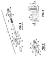
- Fig. 1 is a plan view of a prior art LC connector 11, and Fig. 2 is a cross-thereof along the line I-I of Fig. 1.
- Fig. 3 is an exploded perspective view of an LC connector and Fig. 4 is a perspective view of a detail thereof.
- Connector 11 which, as shown in the several views, is of generally rectangular configuration, comprises a bored housing member 12 which contains, within a bore 15 and axially aligned therein, a ferrule 13 and barrel member 14 to which the ferrule 13 is affixed.
- the barrel member 14 has an enlarged portion or flange 16 which forms a shoulder against which one end of a coiled spring 17, which surrounds the barrel, bears.
- the other end of spring 17 bears against a shoulder formed in the bore 15 within housing 12.
- the ferrule and barrel assembly has a forward bias relative to the housing 12, which, as discussed hereinbefore, insures face-to-face contact of the ferrule end face 18 with the ferrule end face of a mating connector or equipment (not shown).
- the rear of base member 23 has a grooved portion 26 extending axially therefrom onto which jacket 21 or the strength members are gripped. This is made possible by the fact that the glass optical fiber 19 is loosely surrounded by jacket 21 so that jacket 21 may be pulled without affecting fiber 19.
- a protective end plug 27 is shown which protects the end face 18 of ferrule 13 during handling. End plug 27 is, of course, removed prior to installation of the connector.
- FIG. 12 An exterior surface of housing 12, as shown in Figs. 2, 3, and 4, the top surface, has extending therefrom a cantilever latch arm or member 28 having one end 29 affixed to the housing 12, and a free distal end 31 as shown.
- Latch member 28 has first and second lobes or shoulders 32 and 33 which are adapted to engage latching shoulders in the connector receptacle or adapter (not shown).
- latch arm 28 is depressed as the connector is moved forward until a clearance within the adapter allows the lobes 32 and 33 snap into latching engagement with shoulders formed within the adapter.
- a cantilevered trigger member 34 having one end 36 affixed to the housing 12, or it may be affixed to base member 23, has its free end 37 overlying the free end 31 of the latching arm 28.
- the LC type connector has a part count that is undesirably high, as many as seventeen separate parts in a dual installation, for example. Thus, even though it is a relatively simple type of connector and lends itself readily to size reduction, it lacks the requisite low part count to make in-home use with POF entirely feasible. The remainder of the specification deals with modifications to the LC type connector to achieve these desirable ends, although the invention is by no means limited to an LC type connector.
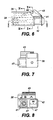
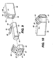
- Figs. 5, 6 and 9 are a plan view and a side elevation and an exploded perspective view of the connector and adapter assembly of the present invention.
- the assembly comprises a receptacle or adapter member 38 having a bore 39 extending therethrough for receiving a connector member 41, as will be discussed more fully hereinafter.
- a trigger holding member 42 having a cantilevered trigger 43 affixed at one end thereof is latched to the connector 41 by latching means 44 on the member 42 and grooves 46 on the connector 41.
- Trigger holding member 42 is shown as a duplex member, i.e., having two openings 47 for receiving connectors 41.
- adapter 38 is shown as a single connector receiving member, although it, too, can be a duplex arrangement.
- trigger holding member 42 may be made integral with connector 41 or otherwise affixed thereto.
- Connector 41 has, a cantilever latching arm 48 affixed at its proximal end 49 to connector 41 as best seen in fig.9.
- Arm 48 is preferably molded with connector 41, either in a single or dual version, of suitable plastic material, and hence, is integral therewith.
- the distal end of the trigger arm 43 overlies the distal end of the latching arm 48 for actuation as described hereinbefore.
- the bore 39 in adapter 38 is rectangular for receiving rectangular connector 41, and opens into a first channel 53 which, in turn, opens into a second channel 54.
- First channel 53 is wide enough to accommodate both camming lobes 52
- second channel 54 is wide enough to accommodate cantilever latch arm 48.
- Adapter 38 itself, is mountable in equipment or on a connector panel or elsewhere by suitable mans, not shown. A better understanding of the construction and functional relationship of the connector 41 and the adapter 38 may be had with reference to Figs. 11 through 20.
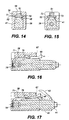
- Fig. 11 which is a cross-sectional view along the line II-II of Fig. 6 shows the configuration and relationship of three basic parts of the connector-adapter assembly of the present invention.
- Connector 41 has a cable or fiber receiving end 56 for receiving a plastic optical fiber 57 and its opaque jacket 58 bonded thereto.
- Optical fiber 57 generally exceeds approximately 300 ⁇ m in diameter.
- Jacket 58 is approximately 0.5 mm thick.
- the operative end 59 of connector 41 has a reentrant construction which forms a tubular ferrule 61, and a bore 62 extends from the front end 59 of connector 41 to the rear end 56.
- Bore 62 has an internally threaded enlarged portion 63 commencing approximately midway between the ends 56 and 59 of connector 41 and extending a short distance toward end 56, as shown.
- An outwardly tapered portion 64 extends from the rear end of the threaded portion 63 to end 56.
- the tapered portion 64 facilitates insertion of the jacketed fiber, with a length of fiber stripped of its jacket, into connector 41. As the jacketed fiber reaches the threaded portion 63, it is further advanced by screwing the soft resilient jacket into the threaded portion 63.
- One of the differences between GOF and POF is that, in GOF, the glass fiber is loose within the jacket, whereas the plastic fiber is fixed within the jacket.
- the external grooves of the standard LC connector cannot be used to affix the POF jacket to the connector.
- the internal threaded portion 63 is used to affix jacket 58 and fiber 57 within the connector.
- the precision of alignment that is required for GOF which requires a ceramic, metallic, or glass ferrule, is not required and the ferrule or support 61 may be molded integrally with the connector 41, and serves primarily as a support for the fiber 57 rather than a precision alignment device, and does not require cementing the fiber therein.
- adapter 38 has a reentrant portion 66 molded integrally therewith and forming a tube 65 for receiving and aligning ferrule 61, which the standard LC connector does not have.
- the trigger holding member 42 is shown in Fig. 11 as latched in place by latch means 44 and latch grooves 46.
- the single fiber connector-adapter assembly comprises three separate parts; the connector 41, the adapter 38, and the trigger holding member 42, although member 42 may be integral with connector 41, in which case there are only two parts, as opposed to at least six parts for the standard LC connector.
- Fig. 12 depicts the connector 41 inserted within adapter 38, and illustrates how the latching tab 51 on the cantilever latching arm 48 snaps into latching position.
- the upper surface of second channel 54 has a sloped portion 67 leading into the adapter 38 which, as the connector moves in the direction of the arrow, forces tab 51 downward. (As will be explained hereinafter, camming lobes 52 also perform this function.)
- Tab 51 and arm 48 remain depressed until tab 51 encounters an opening 68 in adapter 38 which forms a shoulder 69 within second channel 54.
- arm 48 causes latching tab 51 to snap up into opening 68, thus when a force opposite to the direction of the arrow is exerted on connector 41, tab 51 butts against shoulder 69 and prevents connector 41 from being withdrawn, as shown in Figs. 13 and 14.
- Figs. 15, 16, 17, and 18 depict the action of the camming lobes 52 during and after insertion of connector 41 into adapter 38.
- member 42 has been omitted from Fig. 16.
- first channel 53 is slightly wider than latching arm 48 with the two camming lobes 52 on either side thereof so that arm 48 can move freely in a longitudinal or axial direction therein.
- the upper surface of channel 53 is interrupted by the second channel 54, which, being narrower than channel 53, forms first and second narrow camming surfaces 72 and 73.
- first and second narrow camming surfaces 72 and 73 As best seen in Figs.
- surfaces 72 and 73 have a slightly downward slope from the rear of adapter 38 toward the front against which camming lobes 52 slide as the connector 41 is inserted into adapter 38 and pushed forward. This downward slope functions to force latching arm 48 downward as the connector is moved forward.
- a notch 74 is formed in each of the camming surfaces 72 and 73 which has a sloped camming ramp 76 which commences from a point slightly forward of shoulder 69 and slopes upward from rear to front at an angle ⁇ which is preferably in a range of 20° to 45°, with 27.3° being an optimum value.
- Fig. 19 depicts a camming lobe 52 on surface 76
- Fig. 20 depicts the forces thereon, which result from the inherent springiness of the latching arm 48. These forces exist even in the absence of any external force, and there is, as shown in Fig. 20, a resultant downward and forward force labeled P. This forward force is the equivalent of the contacting force supplied by the coil spring in the standard LC connector.
- the connector-adapter assembly as shown in Fig. 18 compensates for over travel in the manner of the coil spring as discussed hereinbefore, and insures that there is always a positive contracting force applied at the face of the ferrule.
- the angle ⁇ of the sloping surface 76 must be chosen to allow variable positioning of the plug or connector 41 to compensate for tolerances on the position controlling features on the connector or plug and the adapter.
- the angle ⁇ must be such that the connector always has a forward axial loading.
- the forward axial force must be greater than frictional resistive force, i.e., the ramp 76 angle ⁇ must be greater than the angle of friction.
- Inequality (4) insures that there is end face contacting force at the optical interface.
- the dimension A, shown in Fig. 12, which is the distance from the bearing face 77 of the latching tab 51 to the optical interface 78 of ferrule 61 is controlled by polishing the bearing face 77 to insure that the latching position shown in Fig. 13 is slightly less than the butting position of interface 78.
- the interaction of the camming lobe 52 with the ramp 76 then insures that a forward biasing force moves the interface 78 into proper butting position, shown in Figs. 12 and 18.
- plug or connector 41 If, after the plug or connector 41 is seated within adapter 38 and the interface 78 bears against a matching fiber interface, a rearward pulling force is applied to the cable or fiber 57 that exceeds the forward bias or load provided by latching arm 48, the plug or connector 41 will move rearward until the bearing face 77 of latching tab 51 butts against shoulder 69, as shown in Fig. 13, for example. Plug 41 will remain in this position until the rearward load is removed, at which time, the forward spring force generated by camming lobes 52 on ramps 76, and the spring action of arm 48, returns the plug 41 to the mating or equilibrium position in contact with a mating connector or other equipment.
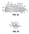
- FIGs. 21, 22, and 23 there is shown a second embodiment of the invention wherein the camming lobes 52 perform a latching function as well as a forward biasing function, thereby eliminating the need for latching tab 51, opening 68, and shoulder 69.
- the camming lobes 52 perform a latching function as well as a forward biasing function, thereby eliminating the need for latching tab 51, opening 68, and shoulder 69.
- sloping ramp 76 terminates in a vertical (relative to the axis) shoulder 81, against which lobes 52 bear in the latched position, as shown in Fig. 21, thereby resisting any axial pulling forces that may occur.
- the connector and adapter with the fiber anchoring threads of the present invention as described in detail hereinbefore have an extremely low parts count.
- there are only two principal parts to the assembly which achieves the same or similar results for POF as the standard LC connector and adapter do for GOF with a relatively large number of parts.
- Assembling the POF to the connector and inserting the connector into the adapter are, with the present inventions, operations that can be performed by virtually anyone, and the whole process can be completed in a minimum amount of time.
- the simplicity of the arrangement enables the user to plug and unplug equipment as easily as is now done for his or her telephone equipment.
Landscapes
- Physics & Mathematics (AREA)
- General Physics & Mathematics (AREA)
- Optics & Photonics (AREA)
- Mechanical Coupling Of Light Guides (AREA)
Claims (7)
- Ein Optische-Faser-Verbinder zur Anbringung an einem Optische-Faser-Kabel, das zumindest eine optische Kunststofffaser (57) aufweist, die durch eine elastische Ummantelung (58) umgeben ist, die einen vorbestimmten Außendurchmesser aufweist, und die mit derselben verbunden ist, wobei der Verbinder ein rohrförmiges Gehäuse (41) umfasst, das eine Verriegelungseinrichtung (48) zum Befestigen desselben an einem zugeordneten Adapter (38) aufweist, wobei das Gehäuse (41) einen sich längs erstreckenden Durchgang (62) umfasst und ein Grenzflächenende (59) und ein Kabeleintrittsende (56) aufweist, wobei der Durchgang dimensioniert ist, um das Optische-Faser-Kabel (57, 58) aufzunehmen,
wobei das Gehäuse (41) ein geformter einheitlicher Kunststoffkörper ist,
wobei der Durchgang (62) einen ersten Abschnitt, der sich von dem Grenzflächenende (59) in Richtung des Kabeleintrittsendes (56) erstreckt, zum Aufnehmen und Halten der optischen Faser (57) in dem Kabel (57, 58) aufweist,
wobei der Durchgang (62) einen zweiten, innen mit einem Gewinde versehenen Abschnitt (63) aufweist, der einen größeren Durchmesser als der erste Abschnitt aufweist, und der sich von dem ersten Abschnitt in Richtung des Kabeleintrittsendes erstreckt, wobei der mit einem Gewinde versehene Abschnitt dimensioniert ist, um die elastische Ummantelung zu greifen, wenn das Kabel in den mit einem Gewinde versehenen Abschnitt eingeschraubt wird; und
wobei der Durchgang (62) einen dritten Abschnitt aufweist, der sich von dem zweiten Abschnitt (63) zu dem Kabeleintrittsende (56) erstreckt, wobei der dritte Abschnitt (64) einen Querschnitt aufweist, der größer als der vorbestimmte Durchmesser der Ummantelung ist, um eine Führung für das Kabel während eines Einfügens desselben in den Verbinder zu liefern. - Ein Verbinder gemäß Anspruch 1, der ferner dadurch gekennzeichnet ist, dass:der Durchgang einen spitz zulaufenden Abschnitt aufweist, der sich von dem innen mit einem Gewinde versehenen Abschnitt in Richtung des Kabeleintrittsendes erstreckt.
- Ein Verbinder gemäß Anspruch 2, der ferner dadurch gekennzeichnet ist, dass:der spitz zulaufende Abschnitt des Durchgangs an dem Kabeleintrittsende eine größere Abmessung als an dem Ende desselben aufweist, das an den innen mit einem Gewinde versehenen Abschnitt angrenzt.
- Ein Optische-Faser-Verbinder, der an einem Endabschnitt eines Optische-Faser-Kabels angebracht ist, in Kombination,
wobei das Kabel eine transparente optische Faser (57) umfasst, die einen ersten vorbestimmten Durchmesser aufweist, und die durch eine lichtundurchlässige elastische Ummantelung (58) umgeben ist, die einen zweiten vorbestimmten Durchmesser aufweist, und die an derselben befestigt ist, wobei ein Abschnitt der Ummantelung von einem Endabschnitt des Optische-Faser-Kabels entfernt ist, um die optische Faser freizulegen,
wobei der Verbinder ein geformtes einheitliches Kunststoffgehäuse (41) aufweist, das ein Grenzflächenende (59) und ein Kabeleintrittsende (56) aufweist, sowie einen länglichen Durchgang (62), der sich zwischen denselben erstreckt,
wobei der Durchgang (62) einen ersten Abschnitt aufweist, der sich von dem Grenzflächenende (59) in Richtung des Kabeleintrittsendes (56) erstreckt, und der dimensioniert ist, um einen Passsitz für die optische Faser, die den ersten Durchmesser aufweist, bereitzustellen,
wobei der Durchgang (62) einen zweiten Abschnitt aufweist, der sich von dem ersten Abschnitt in Richtung des Kabeleintrittsendes erstreckt, wobei der zweite Abschnitt einen innen mit einem Gewinde versehenen Abschnitt (63) aufweist, der dimensioniert ist, um die Ummantelung, die den zweiten Durchmesser aufweist, zu greifen, wobei das Kabel in den mit einem Gewinde versehenen Abschnitt (63) eingeschraubt ist, und
wobei der Durchgang (62) einen dritten Abschnitt (64) aufweist, der sich von dem zweiten Abschnitt zu dem Kabeleintrittsende erstreckt, wobei der dritte Abschnitt (64) einen Querschnitt aufweist, der größer als der zweite vorbestimmte Durchmesser der Ummantelung ist, um eine Führung für das Kabel während einer Einfügung desselben in die Verbindung zu liefern. - Die Kombination gemäß Anspruch 4, bei der der innen mit einem Gewinde versehene Abschnitt ein erstes Ende, das von dem Grenzflächenende beabstandet ist, und ein zweites Ende aufweist, das von dem Kabeleintrittsende beabstandet ist.
- Die Kombination gemäß Anspruch 5, bei der der Durchgang einen kreisförmigen spitz zulaufenden Abschnitt aufweist, der sich von dem zweiten Ende zu dem Kabeleintrittsende erstreckt.
- Die Kombination gemäß Anspruch 5, bei der der spitz zulaufende Abschnitt an dem Kabeleintrittsende einen größeren Durchmesser als an dem zweiten Ende aufweist.
Applications Claiming Priority (2)
| Application Number | Priority Date | Filing Date | Title |
|---|---|---|---|
| US09/019,240 US6017154A (en) | 1998-02-05 | 1998-02-05 | Optical fiber connector with cable anchoring means |
| US19240 | 1998-02-05 |
Publications (3)
| Publication Number | Publication Date |
|---|---|
| EP0935148A2 EP0935148A2 (de) | 1999-08-11 |
| EP0935148A3 EP0935148A3 (de) | 1999-09-22 |
| EP0935148B1 true EP0935148B1 (de) | 2004-10-13 |
Family
ID=21792181
Family Applications (1)
| Application Number | Title | Priority Date | Filing Date |
|---|---|---|---|
| EP99300569A Expired - Lifetime EP0935148B1 (de) | 1998-02-05 | 1999-01-26 | Faseroptischer Stecker mit Kabelbefestigungseinrichtung |
Country Status (4)
| Country | Link |
|---|---|
| US (1) | US6017154A (de) |
| EP (1) | EP0935148B1 (de) |
| JP (2) | JPH11271571A (de) |
| DE (1) | DE69920990T2 (de) |
Families Citing this family (26)
| Publication number | Priority date | Publication date | Assignee | Title |
|---|---|---|---|---|
| US6325547B1 (en) * | 1999-10-06 | 2001-12-04 | Lucent Technologies Inc. | Optical connector having a housing assembly that is comprised of polyphenylsulfone |
| US6464404B1 (en) | 2000-06-19 | 2002-10-15 | Schott Fiber Optics, Inc. | Optical fiber rearrangement method and device |
| US6594437B1 (en) * | 2000-08-15 | 2003-07-15 | Fci Americas Technology, Inc. | Optical fiber separation and regrouping device |
| USD454334S1 (en) | 2000-11-24 | 2002-03-12 | Hirose Electric Co., Ltd. | Electrical connector housing |
| US6852386B2 (en) | 2001-03-08 | 2005-02-08 | Norbord Inc. | Composite board with OSB faces |
| US7396165B2 (en) * | 2002-11-01 | 2008-07-08 | Finisar Corporation | Counterbore base member for ferrule-type optical connector |
| US6947655B2 (en) * | 2003-02-05 | 2005-09-20 | Schott Corporation | Ruggedized optical fiber rearrangement device |
| US20040247252A1 (en) * | 2003-02-28 | 2004-12-09 | John Ehrenreich | Retractable fiber optic connector housing |
| US7198409B2 (en) * | 2003-06-30 | 2007-04-03 | Adc Telecommunications, Inc. | Fiber optic connector holder and method |
| US20050058401A1 (en) * | 2003-07-07 | 2005-03-17 | Charles Maynard | Keyed adapter and connector |
| US7699533B2 (en) * | 2003-09-22 | 2010-04-20 | Belden Cdt (Canada) Inc. | Back-to-back receptacle |
| US7314317B2 (en) * | 2004-03-25 | 2008-01-01 | Kabushiki Kaisha Toshiba | Optical fiber connector and connecting method |
| US20100080517A1 (en) * | 2008-09-29 | 2010-04-01 | Cline Timothy S | Fiber optic connector assembly employing fiber movement support and method of assembly |
| JP2010211024A (ja) * | 2009-03-11 | 2010-09-24 | Fujitsu Ltd | Lcアダプタ |
| WO2012075121A2 (en) | 2010-11-30 | 2012-06-07 | Adc Telecommunications, Inc. | Lc connector and method of assembly |
| CN102540373B (zh) * | 2012-03-12 | 2014-03-05 | 南京云控通信科技有限公司 | 一种用于小规格光缆外皮紧固装置 |
| US9146362B2 (en) | 2012-09-21 | 2015-09-29 | Adc Telecommunications, Inc. | Insertion and removal tool for a fiber optic ferrule alignment sleeve |
| CN104216063A (zh) * | 2014-08-21 | 2014-12-17 | 江苏宇特光电科技股份有限公司 | 现场组装式光纤活动连接器 |
| US10222557B2 (en) * | 2014-09-29 | 2019-03-05 | Us Conec, Ltd. | Spring push with integral trigger |
| GB2538089B (en) * | 2015-05-06 | 2019-06-19 | Fibrefab Ltd | Fibre optic cable assembly |
| WO2016184363A1 (zh) | 2015-05-15 | 2016-11-24 | 爱德奇电讯国际贸易(上海)有限公司 | 对准套管组件和光纤适配器 |
| MY206089A (en) | 2018-08-29 | 2024-11-28 | Commscope Technologies Llc | Indexing cable arrangement and enclosure for use therewith |
| US11194101B2 (en) * | 2018-09-11 | 2021-12-07 | Senko Advanced Components, Inc. | LC one piece front loaded ferrule with unitary retainer and ferrule holder |
| US11971584B2 (en) * | 2019-01-30 | 2024-04-30 | Us Conec Ltd. | Small form factor connector and adapter |
| US11079555B2 (en) | 2019-03-02 | 2021-08-03 | Senko Advanced Components, Inc. | Fiber management enclosure for a fiber optic connector assembly and method of use |
| US11397298B2 (en) * | 2019-05-30 | 2022-07-26 | Us Conec, Ltd. | Adapter to jacketed fiber interface |
Family Cites Families (16)
| Publication number | Priority date | Publication date | Assignee | Title |
|---|---|---|---|---|
| US4934785A (en) * | 1983-08-29 | 1990-06-19 | American Telephone And Telegraph Company | Optical fiber connector |
| AU577099B2 (en) * | 1984-03-19 | 1988-09-15 | E.I. Du Pont De Nemours And Company | Receptacle, plug and optical connector |
| EP0307518B1 (de) * | 1984-06-08 | 1993-07-28 | The Whitaker Corporation | Faseroptischer Stecker hoher Präzision |
| US5157749A (en) * | 1984-06-08 | 1992-10-20 | Amp Incorporated | High precision optical fiber connectors |
| US4687291A (en) * | 1984-06-08 | 1987-08-18 | Amp Incorporated | Duplex electro-fiber connector assembly |
| FR2595149B1 (fr) * | 1986-02-28 | 1988-05-13 | Cit Alcatel | Dispositif d'etancheite longitudinale pour l'ame d'un cable optique |
| US4787706A (en) * | 1987-02-03 | 1988-11-29 | American Telephone And Telegraph Company, At&T Bell Laboratories | Duplex optical fiber connector |
| US5013122A (en) * | 1989-08-29 | 1991-05-07 | Amp Incorporated | Threaded crimping body for fiber optic termination |
| US5073042A (en) * | 1990-06-21 | 1991-12-17 | Amp Incorporated | Coupling bushing for various types of optical fiber connectors |
| US5315684A (en) * | 1991-06-12 | 1994-05-24 | John Mezzalingua Assoc. Inc. | Fiber optic cable end connector |
| US5138678A (en) * | 1991-09-20 | 1992-08-11 | Briggs Robert C | Connector with a variable direction strain relief |
| US5436994A (en) * | 1993-02-26 | 1995-07-25 | Ott; Conrad L. | Ferrule holder for fiber optic connector |
| US5440658A (en) * | 1993-06-29 | 1995-08-08 | Savage, Jr.; John M. | Modular fiber optic cable assembly |
| US5481634A (en) * | 1994-06-24 | 1996-01-02 | At&T Corp. | Connector for optical fiber |
| US5521998A (en) * | 1994-12-13 | 1996-05-28 | United Technologies Corporation | Strain relief backshell for fiber optic transmission lines |
| US5768455A (en) * | 1996-11-19 | 1998-06-16 | Lucent Technologies Inc. | Fiber optic connector |
-
1998
- 1998-02-05 US US09/019,240 patent/US6017154A/en not_active Expired - Lifetime
-
1999
- 1999-01-26 EP EP99300569A patent/EP0935148B1/de not_active Expired - Lifetime
- 1999-01-26 DE DE69920990T patent/DE69920990T2/de not_active Expired - Lifetime
- 1999-02-05 JP JP11028256A patent/JPH11271571A/ja not_active Withdrawn
-
2004
- 2004-01-22 JP JP2004014396A patent/JP3980563B2/ja not_active Expired - Lifetime
Also Published As
| Publication number | Publication date |
|---|---|
| US6017154A (en) | 2000-01-25 |
| DE69920990T2 (de) | 2005-10-20 |
| JPH11271571A (ja) | 1999-10-08 |
| EP0935148A2 (de) | 1999-08-11 |
| DE69920990D1 (de) | 2004-11-18 |
| JP3980563B2 (ja) | 2007-09-26 |
| JP2004118227A (ja) | 2004-04-15 |
| EP0935148A3 (de) | 1999-09-22 |
Similar Documents
| Publication | Publication Date | Title |
|---|---|---|
| US6024498A (en) | Optical fiber connector assembly | |
| EP0935148B1 (de) | Faseroptischer Stecker mit Kabelbefestigungseinrichtung | |
| US6017153A (en) | Optical fiber connector with auxiliary spring | |
| US10795095B2 (en) | MPO optical fiber connector with a backpost having protrusions to align a crimp ring | |
| US6318903B1 (en) | Optical fiber connector for backplane | |
| US6364685B1 (en) | Connector with articulated latch | |
| US6224268B1 (en) | Plug housing with attached cantilevered latch for a fiber optic connector | |
| US4762389A (en) | Optical fiber connector | |
| US6918703B2 (en) | System for terminating optical fibers in a fiber optic connector | |
| US5123071A (en) | Overconnector assembly for a pair of push-pull coupling type optical fiber connectors | |
| US6076974A (en) | Optical fiber connector | |
| US7281859B2 (en) | Optical fiber connector and method of assembly | |
| US5619604A (en) | Multi-fiber optical connector | |
| US7942591B2 (en) | Bend limiting boot | |
| JP3569488B2 (ja) | 一体ハウジングを有する光学コネクタ | |
| CN100480758C (zh) | 小形状因数的可现场安装的连接器 | |
| US20170293091A1 (en) | Hardened fiber optic connector | |
| JPH09329724A (ja) | 固定のフェルールを含む光学コネクタ | |
| EP1193516A2 (de) | Kopplungsadapter für faseroptische Stecker | |
| JPH10170760A (ja) | 光コネクタ |
Legal Events
| Date | Code | Title | Description |
|---|---|---|---|
| PUAI | Public reference made under article 153(3) epc to a published international application that has entered the european phase |
Free format text: ORIGINAL CODE: 0009012 |
|
| PUAL | Search report despatched |
Free format text: ORIGINAL CODE: 0009013 |
|
| AK | Designated contracting states |
Kind code of ref document: A2 Designated state(s): DE FR GB |
|
| AX | Request for extension of the european patent |
Free format text: AL;LT;LV;MK;RO;SI |
|
| AK | Designated contracting states |
Kind code of ref document: A3 Designated state(s): AT BE CH CY DE DK ES FI FR GB GR IE IT LI LU MC NL PT SE |
|
| AX | Request for extension of the european patent |
Free format text: AL;LT;LV;MK;RO;SI |
|
| 17P | Request for examination filed |
Effective date: 20000309 |
|
| AKX | Designation fees paid |
Free format text: DE FR GB |
|
| 17Q | First examination report despatched |
Effective date: 20030115 |
|
| GRAP | Despatch of communication of intention to grant a patent |
Free format text: ORIGINAL CODE: EPIDOSNIGR1 |
|
| GRAS | Grant fee paid |
Free format text: ORIGINAL CODE: EPIDOSNIGR3 |
|
| GRAA | (expected) grant |
Free format text: ORIGINAL CODE: 0009210 |
|
| AK | Designated contracting states |
Kind code of ref document: B1 Designated state(s): DE FR GB |
|
| REG | Reference to a national code |
Ref country code: GB Ref legal event code: FG4D |
|
| REF | Corresponds to: |
Ref document number: 69920990 Country of ref document: DE Date of ref document: 20041118 Kind code of ref document: P |
|
| ET | Fr: translation filed | ||
| PLBE | No opposition filed within time limit |
Free format text: ORIGINAL CODE: 0009261 |
|
| STAA | Information on the status of an ep patent application or granted ep patent |
Free format text: STATUS: NO OPPOSITION FILED WITHIN TIME LIMIT |
|
| 26N | No opposition filed |
Effective date: 20050714 |
|
| PGFP | Annual fee paid to national office [announced via postgrant information from national office to epo] |
Ref country code: DE Payment date: 20150128 Year of fee payment: 17 |
|
| REG | Reference to a national code |
Ref country code: FR Ref legal event code: PLFP Year of fee payment: 18 |
|
| REG | Reference to a national code |
Ref country code: DE Ref legal event code: R119 Ref document number: 69920990 Country of ref document: DE |
|
| PG25 | Lapsed in a contracting state [announced via postgrant information from national office to epo] |
Ref country code: DE Free format text: LAPSE BECAUSE OF NON-PAYMENT OF DUE FEES Effective date: 20160802 |
|
| REG | Reference to a national code |
Ref country code: FR Ref legal event code: PLFP Year of fee payment: 19 |
|
| PGFP | Annual fee paid to national office [announced via postgrant information from national office to epo] |
Ref country code: FR Payment date: 20170327 Year of fee payment: 19 |
|
| PGFP | Annual fee paid to national office [announced via postgrant information from national office to epo] |
Ref country code: GB Payment date: 20170227 Year of fee payment: 19 |
|
| GBPC | Gb: european patent ceased through non-payment of renewal fee |
Effective date: 20180126 |
|
| PG25 | Lapsed in a contracting state [announced via postgrant information from national office to epo] |
Ref country code: FR Free format text: LAPSE BECAUSE OF NON-PAYMENT OF DUE FEES Effective date: 20180131 |
|
| REG | Reference to a national code |
Ref country code: FR Ref legal event code: ST Effective date: 20180928 |
|
| PG25 | Lapsed in a contracting state [announced via postgrant information from national office to epo] |
Ref country code: GB Free format text: LAPSE BECAUSE OF NON-PAYMENT OF DUE FEES Effective date: 20180126 |