EP0935038B1 - Universal I-shaped fence post with matching securing devices for fixing welded wire mesh to the post - Google Patents
Universal I-shaped fence post with matching securing devices for fixing welded wire mesh to the post Download PDFInfo
- Publication number
- EP0935038B1 EP0935038B1 EP98204202A EP98204202A EP0935038B1 EP 0935038 B1 EP0935038 B1 EP 0935038B1 EP 98204202 A EP98204202 A EP 98204202A EP 98204202 A EP98204202 A EP 98204202A EP 0935038 B1 EP0935038 B1 EP 0935038B1
- Authority
- EP
- European Patent Office
- Prior art keywords
- fence post
- post
- wire mesh
- welded wire
- flanges
- Prior art date
- Legal status (The legal status is an assumption and is not a legal conclusion. Google has not performed a legal analysis and makes no representation as to the accuracy of the status listed.)
- Expired - Lifetime
Links
- 238000010276 construction Methods 0.000 claims description 3
- 229910000831 Steel Inorganic materials 0.000 description 4
- 210000000481 breast Anatomy 0.000 description 4
- 239000010959 steel Substances 0.000 description 4
- 238000000034 method Methods 0.000 description 2
- 229920003023 plastic Polymers 0.000 description 2
- 239000004033 plastic Substances 0.000 description 2
- 230000004308 accommodation Effects 0.000 description 1
- 230000002411 adverse Effects 0.000 description 1
- 238000005452 bending Methods 0.000 description 1
- 230000002950 deficient Effects 0.000 description 1
- 238000005516 engineering process Methods 0.000 description 1
- 238000003780 insertion Methods 0.000 description 1
- 230000037431 insertion Effects 0.000 description 1
- 239000000463 material Substances 0.000 description 1
- 238000003825 pressing Methods 0.000 description 1
- 238000003466 welding Methods 0.000 description 1
Images



Classifications
-
- E—FIXED CONSTRUCTIONS
- E04—BUILDING
- E04H—BUILDINGS OR LIKE STRUCTURES FOR PARTICULAR PURPOSES; SWIMMING OR SPLASH BATHS OR POOLS; MASTS; FENCING; TENTS OR CANOPIES, IN GENERAL
- E04H17/00—Fencing, e.g. fences, enclosures, corrals
- E04H17/14—Fences constructed of rigid elements, e.g. with additional wire fillings or with posts
- E04H17/16—Fences constructed of rigid elements, e.g. with additional wire fillings or with posts using prefabricated panel-like elements, e.g. wired frames
- E04H17/161—Fences constructed of rigid elements, e.g. with additional wire fillings or with posts using prefabricated panel-like elements, e.g. wired frames using wire panels
-
- E—FIXED CONSTRUCTIONS
- E04—BUILDING
- E04H—BUILDINGS OR LIKE STRUCTURES FOR PARTICULAR PURPOSES; SWIMMING OR SPLASH BATHS OR POOLS; MASTS; FENCING; TENTS OR CANOPIES, IN GENERAL
- E04H17/00—Fencing, e.g. fences, enclosures, corrals
- E04H17/14—Fences constructed of rigid elements, e.g. with additional wire fillings or with posts
- E04H17/16—Fences constructed of rigid elements, e.g. with additional wire fillings or with posts using prefabricated panel-like elements, e.g. wired frames
- E04H17/168—Fences constructed of rigid elements, e.g. with additional wire fillings or with posts using prefabricated panel-like elements, e.g. wired frames using panels fitted in grooves of posts
Definitions
- the present invention relatates to a fence post with a substantially I-shaped cross-section consisting of one central portion and two flanges securing therein the edge wire members of two welded wire mesh panels adjacent to the fence post.
- Such a fence post is known from FR-A-2698417.
- European patent applications 0478454 and 0596825 describe very typical fence posts to accommodate welded wire mesh panels, each fence post in reality consisting of a double post, i.e., one fence post with a round or a rectangular cross section, and one connecting I-shaped post.
- the I-shaped post always accommodates the two welded wire mesh panels adjacent to the post.
- a further disadvantage of the fence post according to the European patent application 0478454 is the defective connection of the welded wire mesh panels to the post, in that the fastening elements used can be disengaged with ease, as described, inter alia, in the introduction of the European patent application 0596825.
- a further disadvantage of the fence post according to the European patent application 0596825 is the relatively time-consuming procedure for the securing of the panels to the central portion of the I-shaped fence post.
- the present invention aims to provide a universally useful fence post of the type mentioned in the introduction which would avoid the above-mentioned problems.
- both flanges of the I-shaped fence post are hollow and have internal apertures accommodating the securing devices.
- Fig. 1 shows a universal I-shaped fence post 1 according to the present invention.
- the fence post 1 has a practically I-shaped cross-section, consisting of a central portion 2 and two flanges 3 and 4.
- the fence post is preferably made of sheet steel of a thickness of 1 mm to 2 mm. It is, for example, possible to form a fence post 1 of sheet steel by bending the plate to the desired I profile and then welding it shut. It is also possible to form the fence post 1 from hollow extruded tubes.
- the fence post 1 is preferably of hollow construction.
- the flanges 3 and 4 of the I-shaped fence post 1 have internal apertures or notches 5 and 6 at regular intervals from each other.
- apertures or notches 5 and 6 do not necessarily have to be spaced at regular intervals.
- the apertures or notches 5 and 6 can be made in the sheet steel by cutting out the sheet steel at the points of the desired apertures for most of the perimeter of the aperture and then pressing it out into the hollow interior of fence post 1. This is, for example, clearly shown in fence post 1 in Fig. 8. The purpose of these apertures or notches 5 and 6 will be explained in more detail later.
- Fig. 1 shows how a three-dimensional panel of welded wire mesh 7 is secured between the flanges 3 and 4.
- the panel 7 consists of upright or vertical wires 8 and transverse or horizontal wires 9. welded together.
- the panel 7 is provided with some breasts 10 in the transverse direction to give the panel 7 an increased rigidity.
- the depth of the breasts 10 roughly corresponds with the distance between the flanges 3 and 4.
- the depth of the breast 10 is preferably smaller than the distance between the flanges 3 and 4.
- the panel 7 is fixed to the fence post 1 by means of special securing devices 11.
- Each securing device 11 features a groove-like longitudinal channel 12 and at least two pens or studs 13 and 14.
- the dimensions of the studs 13 and 14 correspond with the dimensions of the apertures 5 and 6 in the flanges 3 and 4 in such a way that the studs 13 and 14 can engage solidly in the apertures 5 and 6.
- Fig. 1 shows how such a securing device 11 can fix a panel 7 between the flanges 3 and 4 of the post to the I - shaped fence post 1.
- the longitudinal channel 12 of the securing device 11 is pushed over the vertical wire 8 and the studs 13 and 14 are driven into the notches 5 and 6 of the flanges 3 and 4 by means of, e.g.. a hammer. It is, for example, possible to attach three securing devices over the full height of the fence post 1. thus making it impossible for the panel 7 to be moved off in the vertical direction.
- Fig. 2 shows how a flat welded wire mesh panel 7 with the same securing device 11 is fastened to the same I - shaped fence post 1. It is apparent that the same I - shaped fence post 1 with the same securing devices 11 can be used to trap a totally different welded wire mesh panel 7 against the fence post 1. This brings out directly the universal application of the new fence post 1 and its accessory securing devices 11 to fasten welded wire mesh panels to fence post 1 according to the present invention.
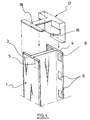
- Fig. 4 shows a slightly modified embodiment of the fence post 1 shown in Fig. 1 and 2, in which the hollow I-shaped fence post 1 can be fitted with a cap 17, with hooks 18, made to the cross-sectional dimension of the fence post 1.
- the cap 17 can be pressed over the top of the fence post 1 and fastened, the hollow interior of the fence post 1 thus being completely sealed by the cap 17.
- the two panels 7 adjacent to the fence post 1 are being secured, the two panels 7 are first hung by the topmost horizontal wire 9 on the hooks 18 of the cap 17 fitted to the fence post 1. as a result of which the cap 17 is gripped more tightly in place atop the hollow post 1.
- the actual securing devices 11 are then fitted into their corresponding apertures 5 and 6 in the flanges 3 and 4. Once the securing devices 11 have been fitted, the cap 17 cannot be removed from the hollow post 1. It is clear that the mounting and securing of the panels 7 on the post 1 can be easily managed by one person thanks to the panels 7 being hung from the hooks 18.
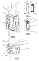
- Fig. 5 shows a perspective view of the detail of a securing device 11 with groove-like channel 12 and two protrusions or studs 13 and 14. where the edge wire 8 of a panel 7 is engaged in the groove-like channel 12.
- the construction of the securing device 11 is preferably of a hard plastic and, as Fig. 5 shows, it is possible to have the studs 13 and 14 can be pressed into the securing device 11 to facilitate the insertion of the studs 13 and 14 in their corresponding apertures 5 and 6.
- the gripping action of the studs 13 and 14 can be obtained in various ways : e.g., by the correct choice of material of the securing device 11, the thickness of the securing device.... as generally known in plastics technology.
- Figs. 6a and 6b show, in plan view or in cross section, a section of a fence post 1 with a matching securing device 11 with an engaged edge wire member 8 before and after the fitting of the securing device 11 in the flanges 3 and 4 of the I-shaped fence post 1.
- Fig. 7 shows a perspective view of the detail of a modified embodiment of a securing device 11 according to the present invention.
- the securing device 11 still has a longitudinal groove 12 to accommodate an edge wire member 8. but the securing device 11 here also has a transverse aperture 19 to accommodate a horizontal wire member 9.
- a flat panel of welded wire mesh as shown in Fig. 2, or with a three-dimensional panel of welded wire mesh, of which the height of the breasts 10 is less than the distance between the flanges 3 and 4 of the fence post 1 : it is possible to rotate the panel 7 in relation to the fence post 1 through a certain angle around the edge wire member 8. This can be useful if the fencing does not follow a rectilinear course.
- Fig. 8 shows a perspective view, as in Fig. 4. of another slightly modified embodiment of a fence post 1 according to the present invention, with cap 17 and one securing device 11.
- the securing device 11 features a groove-like longitudinal channel 12 for the accommodation of an edge wire member 8 and, also, a transverse aperture 19 for the possible inclusion of a transverse wire member 9.
- the securing device 11 is also fitted with four small protrusions or studs 13 and 14. The dimensions of these studs 13 and 14 correspond to the dimensions of the apertures 5 and 6 in the flanges 3 and 4 : during assembly, the two studs 13 snap into the two notches 5 and the two studs 14 snap into the two notches 6.
- the cap 17 shows a cross-sectional form adapted to the profile of the fence post 1. the hollow interior of the fence post 1 being thus completely sealed when the cap 17 is pressed on top of the fence post 1.
- the cap 17 is provided with two hooks 18 to engage the top horizontal wires 9 of the two panels 7 adjacent to the fence post 1.
Landscapes
- Engineering & Computer Science (AREA)
- Architecture (AREA)
- Civil Engineering (AREA)
- Structural Engineering (AREA)
- Fencing (AREA)
Description
- The present invention relatates to a fence post with a substantially I-shaped cross-section consisting of one central portion and two flanges securing therein the edge wire members of two welded wire mesh panels adjacent to the fence post.
- Such a fence post is known from FR-A-2698417.
- Other posts with a substantially I-shaped cross-section are known from US-A-5702090 ; US-A-4007919 ; GB-A-2248643 and FR-A-2554156.
- Fastening welded wire mesh panels to posts is a common technique for forming a fencing section. Special fence posts for the securing thereto of welded wire mesh panels are also described, inter alia, in European patent applications 0368778, 0478454, 0481100 and 0596825.
- European patent applications 0478454 and 0596825 describe very typical fence posts to accommodate welded wire mesh panels, each fence post in reality consisting of a double post, i.e., one fence post with a round or a rectangular cross section, and one connecting I-shaped post. The I-shaped post always accommodates the two welded wire mesh panels adjacent to the post.
- One serious disadvantage of such fence posts according to European patent applications 0478454 and 0596825 is the special design of the posts, i.e. the double structure of these posts, which adversely affects the cost price.
- A further disadvantage of the fence post according to the European patent application 0478454 is the defective connection of the welded wire mesh panels to the post, in that the fastening elements used can be disengaged with ease, as described, inter alia, in the introduction of the European patent application 0596825.
- A further disadvantage of the fence post according to the European patent application 0596825 is the relatively time-consuming procedure for the securing of the panels to the central portion of the I-shaped fence post.
- The present invention aims to provide a universally useful fence post of the type mentioned in the introduction which would avoid the above-mentioned problems.
- Accordingly, the present invention proposes that both flanges of the I-shaped fence post are hollow and have internal apertures accommodating the securing devices.
- Other embodiments and advantages of the post according to the present invention Will now be explained in more detail with reference to the accompanying drawing, in which :
- Fig. 1
- shows a perspective view of a universal I-shaped post according to the invention and a matching securing device for holding a three-dimensional welded wire mesh panel to the fence post ;
- Fig. 2
- shows a perspective view of the same post as in Fig. 1 for securing a flat panel of welded wire mesh to the post ;
- Fig. 4
- shows a perspective view of a universal I-shaped fence post according to the present invention with a matching cap ;
- Fig. 5
- shows a detailed perspective view of the securing device according to Fig. 1 ;
- Figs. 6a and 6b
- show a plan view of a fence post with a matching securing device in open and closed position :
- Fig. 7.
- shows a detailed perspective view, as in Fig. 5, of the modified embodiment of a securing device according to the present invention ; and
- Fig. 8.
- shows a perspective view, as in Fig. 4, of another alternative embodiment of the fence post according to the present invention with cap and securing device.
- Fig. 1 shows a universal I-
shaped fence post 1 according to the present invention. Thefence post 1 has a practically I-shaped cross-section, consisting of acentral portion 2 and twoflanges fence post 1 of sheet steel by bending the plate to the desired I profile and then welding it shut. It is also possible to form thefence post 1 from hollow extruded tubes. Thefence post 1 is preferably of hollow construction. Theflanges shaped fence post 1 have internal apertures ornotches notches notches fence post 1. This is, for example, clearly shown infence post 1 in Fig. 8. The purpose of these apertures ornotches - Fig. 1 shows how a three-dimensional panel of
welded wire mesh 7 is secured between theflanges panel 7 consists of upright orvertical wires 8 and transverse orhorizontal wires 9. welded together. Thepanel 7 is provided with somebreasts 10 in the transverse direction to give thepanel 7 an increased rigidity. The depth of thebreasts 10 roughly corresponds with the distance between theflanges breast 10 is preferably smaller than the distance between theflanges panel 7 is fixed to thefence post 1 by means ofspecial securing devices 11. - Each
securing device 11 features a groove-likelongitudinal channel 12 and at least two pens orstuds studs apertures flanges studs apertures - Fig. 1 shows how such a
securing device 11 can fix apanel 7 between theflanges shaped fence post 1. Thelongitudinal channel 12 of thesecuring device 11 is pushed over thevertical wire 8 and thestuds notches flanges fence post 1. thus making it impossible for thepanel 7 to be moved off in the vertical direction. - Fig. 2 shows how a flat welded
wire mesh panel 7 with thesame securing device 11 is fastened to the same I -shaped fence post 1. It is apparent that the same I -shaped fence post 1 with the samesecuring devices 11 can be used to trap a totally different weldedwire mesh panel 7 against thefence post 1. This brings out directly the universal application of thenew fence post 1 and its accessory securingdevices 11 to fasten welded wire mesh panels to fencepost 1 according to the present invention. - Fig. 4 shows a slightly modified embodiment of the
fence post 1 shown in Fig. 1 and 2, in which the hollow I-shaped fence post 1 can be fitted with acap 17, withhooks 18, made to the cross-sectional dimension of thefence post 1. Thecap 17 can be pressed over the top of thefence post 1 and fastened, the hollow interior of thefence post 1 thus being completely sealed by thecap 17. When the twopanels 7 adjacent to thefence post 1 are being secured, the twopanels 7 are first hung by the topmosthorizontal wire 9 on thehooks 18 of thecap 17 fitted to thefence post 1. as a result of which thecap 17 is gripped more tightly in place atop thehollow post 1. Theactual securing devices 11 are then fitted into theircorresponding apertures flanges securing devices 11 have been fitted, thecap 17 cannot be removed from thehollow post 1. It is clear that the mounting and securing of thepanels 7 on thepost 1 can be easily managed by one person thanks to thepanels 7 being hung from thehooks 18. - Fig. 5 shows a perspective view of the detail of a
securing device 11 with groove-like channel 12 and two protrusions orstuds edge wire 8 of apanel 7 is engaged in the groove-like channel 12. The construction of thesecuring device 11 is preferably of a hard plastic and, as Fig. 5 shows, it is possible to have thestuds securing device 11 to facilitate the insertion of thestuds corresponding apertures studs device 11, the thickness of the securing device.... as generally known in plastics technology. - Figs. 6a and 6b show, in plan view or in cross section, a section of a
fence post 1 with amatching securing device 11 with an engagededge wire member 8 before and after the fitting of the securingdevice 11 in theflanges fence post 1. - Fig. 7 shows a perspective view of the detail of a modified embodiment of a securing
device 11 according to the present invention. The securingdevice 11 still has alongitudinal groove 12 to accommodate anedge wire member 8. but the securingdevice 11 here also has atransverse aperture 19 to accommodate ahorizontal wire member 9. With a flat panel of welded wire mesh, as shown in Fig. 2, or with a three-dimensional panel of welded wire mesh, of which the height of thebreasts 10 is less than the distance between theflanges panel 7 in relation to thefence post 1 through a certain angle around theedge wire member 8. This can be useful if the fencing does not follow a rectilinear course. - Fig. 8 shows a perspective view, as in Fig. 4. of another slightly modified embodiment of a
fence post 1 according to the present invention, withcap 17 and onesecuring device 11. The securingdevice 11 features a groove-likelongitudinal channel 12 for the accommodation of anedge wire member 8 and, also, atransverse aperture 19 for the possible inclusion of atransverse wire member 9. The securingdevice 11 is also fitted with four small protrusions orstuds studs apertures flanges 3 and 4 : during assembly, the twostuds 13 snap into the twonotches 5 and the twostuds 14 snap into the twonotches 6. Thecap 17 shows a cross-sectional form adapted to the profile of thefence post 1. the hollow interior of thefence post 1 being thus completely sealed when thecap 17 is pressed on top of thefence post 1. Thecap 17 is provided with twohooks 18 to engage the tophorizontal wires 9 of the twopanels 7 adjacent to thefence post 1.
Claims (5)
- A fence post (1) with a substantially I-shaped cross-section consisting of one central portion (2) and two flanges (3, 4) securing therein the edge wire members (8) of two welded wire mesh panels (7) adjacent to the fence post by means of securing devices (11), characterized in that both flanges (3, 4) of the I-shaped fence post (1) are hollow and have internal apertures (5, 6) accommodating the securing devices (11).
- A fence post according to claim 1, characterized in that the fence post (1) is of hollow construction.
- A fence post (1) according to claim 1 or claim 2, whereby each securing device (11) is provided with a groove-like longitudinal channel (12) accommodating the edge wire member (8) of the welded wire mesh panel (7) adjacent to the fence post, characterized in that each securing device (11) is fitted with at least two protrusions or studs (13, 14) corresponding to the apertures (5, 6) in the flanges (3, 4) engaging the studs (13, 14) solidly in the apertures or notches (5, 6) of the flanges (3, 4).
- A fence post (1) according to claim 3, characterized in that each securing device (11) has an additional transverse aperture (19) engaging a horizontal wire member (9) of the adjacent welded wire mesh panel (7).
- A fence post (1) according to one or more of the claims 1 - 4, characterized in that the fence post (1) is provided with a cap (17) adapted to the cross-sectional dimension of the fence post (1) ; the cap (17) has hooks (18) engaging the top horizontal wires (9) of the two welded wire mesh panels (7) adjacent to the fence post (1).
Applications Claiming Priority (2)
| Application Number | Priority Date | Filing Date | Title |
|---|---|---|---|
| BE9800080 | 1998-02-04 | ||
| BE9800080A BE1011725A3 (en) | 1998-02-04 | 1998-02-04 | UNIVERSAL T-SHAPED POST ENTRY CLAMP BODIES FOR SUBSEQUENT ATTACHING PANELS welded mesh. |
Publications (2)
| Publication Number | Publication Date |
|---|---|
| EP0935038A1 EP0935038A1 (en) | 1999-08-11 |
| EP0935038B1 true EP0935038B1 (en) | 2006-02-22 |
Family
ID=3891071
Family Applications (1)
| Application Number | Title | Priority Date | Filing Date |
|---|---|---|---|
| EP98204202A Expired - Lifetime EP0935038B1 (en) | 1998-02-04 | 1998-12-10 | Universal I-shaped fence post with matching securing devices for fixing welded wire mesh to the post |
Country Status (4)
| Country | Link |
|---|---|
| EP (1) | EP0935038B1 (en) |
| BE (1) | BE1011725A3 (en) |
| ES (1) | ES2259450T3 (en) |
| PT (1) | PT935038E (en) |
Families Citing this family (26)
| Publication number | Priority date | Publication date | Assignee | Title |
|---|---|---|---|---|
| FR2807777B1 (en) * | 2000-04-14 | 2002-08-09 | A F T | DEVICE FOR ASSEMBLING POSTS AND PANELS |
| ES2170661B1 (en) * | 2000-05-05 | 2004-03-01 | Sotillos Jorge Antonio Saura | MODULAR Fence. |
| NL1018715C2 (en) * | 2001-06-21 | 2002-12-30 | Trios B V | Plate assembly, a plate, a coupling structure and locking means therefor. |
| FR2831583B1 (en) * | 2001-10-31 | 2004-03-12 | Rene Bosmy Soc Normande De Clo | FENCE COMPRISING A PLURALITY OF POSTS AND LATTICE PANELS AND METHOD FOR LAYING SUCH A FENCE |
| US7475868B1 (en) | 2002-04-05 | 2009-01-13 | Gibbs Edward L | Cable fence system |
| US6874767B1 (en) | 2002-04-05 | 2005-04-05 | Fence | |
| GB2387609B (en) * | 2002-04-17 | 2005-09-28 | Hadley Ind Plc | Security fencing |
| GB2409215A (en) * | 2002-09-06 | 2005-06-22 | Siddall & Hilton Ltd | Wire fencing |
| US7441751B1 (en) | 2003-10-06 | 2008-10-28 | Gibbs Edward L | Cable fence system |
| USD572374S1 (en) | 2004-01-26 | 2008-07-01 | Gibbs Edward L | Cable-reinforced bollard fence |
| ATE358220T1 (en) * | 2004-02-13 | 2007-04-15 | Betafence Holding Nv | FENCE CONSTRUCTION WITH FENCE POSTS AND FLAT GRID PANELS ATTACHED TO THEM |
| DE202004019871U1 (en) | 2004-12-20 | 2005-03-03 | H.F. Finke Gmbh & Co. | Fence system, grid element and connector for fence system |
| FR2901826B1 (en) * | 2006-06-06 | 2010-08-27 | Clotures Michel Willoquaux | BRACKET FOR FIXING A CLOSURE PANEL |
| FR2908440B1 (en) * | 2006-11-10 | 2009-01-30 | Moreda Riviere Trefilerias S A | GYRATORY PIECE FOR FASTENING A GRID PANEL TO A CLOSING PROFILE. |
| PT2088262E (en) | 2008-02-08 | 2012-05-21 | Moreda Riviere Trefilerias S A | Profile for obtaining fence posts for fixing panels without fittings |
| AT512911B1 (en) * | 2012-05-15 | 2013-12-15 | Martin Fitz | Safety fence |
| BE1021457B1 (en) * | 2012-11-29 | 2015-11-26 | Betafence Holding Nv | SAFETY FENCE PANEL AND SAFETY FENCE |
| ES3014484T3 (en) * | 2018-02-01 | 2025-04-22 | Picot | Part for attaching at least one mesh panel to a fence post, corresponding fence post |
| FR3077320A1 (en) * | 2018-02-01 | 2019-08-02 | Dirickx Groupe | HOLLOW CLOSURE POST, FIXING SYSTEM AND INTERNAL REINFORCEMENT |
| GB2575681B (en) * | 2018-07-20 | 2020-07-22 | Bja Trading Ltd | Fence Post |
| GB2570964B (en) | 2018-02-09 | 2022-04-27 | Bja Trading Ltd | Improvements in and relating to fencing |
| GB2570912B (en) * | 2018-02-09 | 2020-10-14 | Bja Trading Ltd | Fence post assemblies |
| FR3084899B1 (en) * | 2018-08-13 | 2024-04-12 | Sarl Clotures Et Portails De France | ACCESSORY FOR FIXING A GRIDING PANEL TO A FENCE POST COMPRISING A LOCKING PIECE AND A CLAMPING PIECE |
| FR3093122B1 (en) * | 2019-02-25 | 2022-04-22 | Eurofence | Fence installation kit |
| BE1027974B1 (en) * | 2020-01-09 | 2021-08-10 | Van Houtven Bjoern Marc E | Support post for a fence and fence equipped with it |
| GB2591736B (en) | 2020-01-20 | 2023-02-01 | Praesidiad Holding Bvba | Securing device for fence |
Family Cites Families (10)
| Publication number | Priority date | Publication date | Assignee | Title |
|---|---|---|---|---|
| US4007919A (en) * | 1975-07-24 | 1977-02-15 | Totten Clyde D | Fence structure |
| FR2554156B1 (en) * | 1983-11-02 | 1986-05-09 | Gantois | IMPROVED WELDED FENCE |
| FR2638776B1 (en) | 1988-11-09 | 1991-08-02 | Gantois Ets | IMPROVEMENT IN FENCE WITH WELDED MESH |
| FR2667103B1 (en) | 1990-09-26 | 1996-11-29 | Const Prefabriquees Mont | IMPROVEMENT ON POSTS FOR FENCING. |
| EP0481100B1 (en) | 1990-10-09 | 1993-04-14 | Malkmus-Dörnemann, Carola, Dr. | Clip for fastening grid-shaped fencing panels to fence posts |
| GB2248643A (en) * | 1990-10-11 | 1992-04-15 | Parkes Products Limited | Fence post assemblies |
| FR2697565B1 (en) | 1992-11-02 | 1995-01-06 | Willoquaux Michel | Method of mounting a fence, means for its implementation and fences thus obtained. |
| FR2698417B1 (en) * | 1992-11-24 | 1995-02-10 | Plastil | Device for assembling posts and panels. |
| BE1007664A3 (en) * | 1993-10-21 | 1995-09-05 | Bekaert Sa Nv | Closure with bars panels. |
| US5702090A (en) * | 1995-08-07 | 1997-12-30 | Vinylex Corporation | Snap together plastic fence |
-
1998
- 1998-02-04 BE BE9800080A patent/BE1011725A3/en not_active IP Right Cessation
- 1998-12-10 PT PT98204202T patent/PT935038E/en unknown
- 1998-12-10 EP EP98204202A patent/EP0935038B1/en not_active Expired - Lifetime
- 1998-12-10 ES ES98204202T patent/ES2259450T3/en not_active Expired - Lifetime
Also Published As
| Publication number | Publication date |
|---|---|
| PT935038E (en) | 2006-07-31 |
| ES2259450T3 (en) | 2006-10-01 |
| EP0935038A1 (en) | 1999-08-11 |
| BE1011725A3 (en) | 1999-12-07 |
Similar Documents
| Publication | Publication Date | Title |
|---|---|---|
| EP0935038A1 (en) | Universal I-shaped fence post with matching securing devices for fixing welded wire mesh to the post | |
| AU641745B2 (en) | Office space dividing system | |
| US4369953A (en) | Fence constructions and in fence elements therefor | |
| US7934699B2 (en) | Fence system | |
| WO2003052220A1 (en) | Fencing system | |
| CN102414383A (en) | Fence | |
| US5636936A (en) | Connector assembly for joining structural members | |
| US4832316A (en) | Wall security fixtures | |
| GB2259923A (en) | "Fencing connectors" | |
| GB2338770A (en) | Connecting device for parallel posts | |
| EP0503952A1 (en) | A fence assembly and panel | |
| JPH10184107A (en) | Panel fence | |
| GB2202604A (en) | Joining posts | |
| JP2699806B2 (en) | Wall panels and walls | |
| EP0222456A2 (en) | Ventilation device with louvred slat walls | |
| JP2891148B2 (en) | Wall panels and structures | |
| JPH10121791A (en) | Mesh fence | |
| JPH0819145A (en) | Contact insulation type bus duct | |
| GB2268524A (en) | Framed panels | |
| GB2374877A (en) | Fence security device | |
| JP2766469B2 (en) | Panel assembly structure | |
| JP2932374B2 (en) | Corner cover for piping | |
| GB2153403A (en) | Adjustable fence post support | |
| GB2427208A (en) | Fencing with flanged box - section post | |
| JPH01299944A (en) | Structure of attaching column cover to column |
Legal Events
| Date | Code | Title | Description |
|---|---|---|---|
| PUAI | Public reference made under article 153(3) epc to a published international application that has entered the european phase |
Free format text: ORIGINAL CODE: 0009012 |
|
| AK | Designated contracting states |
Kind code of ref document: A1 Designated state(s): BE ES FR GB IT LU NL PT |
|
| AX | Request for extension of the european patent |
Free format text: AL;LT;LV;MK;RO;SI |
|
| 17P | Request for examination filed |
Effective date: 19991231 |
|
| AKX | Designation fees paid |
Free format text: BE ES FR GB IT LU NL PT |
|
| 17Q | First examination report despatched |
Effective date: 20030409 |
|
| REG | Reference to a national code |
Ref country code: DE Ref legal event code: 8566 |
|
| RAP1 | Party data changed (applicant data changed or rights of an application transferred) |
Owner name: BETAFENCE HOLDING |
|
| GRAP | Despatch of communication of intention to grant a patent |
Free format text: ORIGINAL CODE: EPIDOSNIGR1 |
|
| GRAS | Grant fee paid |
Free format text: ORIGINAL CODE: EPIDOSNIGR3 |
|
| GRAA | (expected) grant |
Free format text: ORIGINAL CODE: 0009210 |
|
| AK | Designated contracting states |
Kind code of ref document: B1 Designated state(s): BE ES FR GB IT LU NL PT |
|
| REG | Reference to a national code |
Ref country code: GB Ref legal event code: FG4D |
|
| REG | Reference to a national code |
Ref country code: PT Ref legal event code: SC4A Effective date: 20060515 |
|
| ET | Fr: translation filed | ||
| REG | Reference to a national code |
Ref country code: ES Ref legal event code: FG2A Ref document number: 2259450 Country of ref document: ES Kind code of ref document: T3 |
|
| PLBE | No opposition filed within time limit |
Free format text: ORIGINAL CODE: 0009261 |
|
| STAA | Information on the status of an ep patent application or granted ep patent |
Free format text: STATUS: NO OPPOSITION FILED WITHIN TIME LIMIT |
|
| 26N | No opposition filed |
Effective date: 20061123 |
|
| PGFP | Annual fee paid to national office [announced via postgrant information from national office to epo] |
Ref country code: NL Payment date: 20141219 Year of fee payment: 17 |
|
| REG | Reference to a national code |
Ref country code: FR Ref legal event code: PLFP Year of fee payment: 18 |
|
| REG | Reference to a national code |
Ref country code: NL Ref legal event code: MM Effective date: 20160101 |
|
| PG25 | Lapsed in a contracting state [announced via postgrant information from national office to epo] |
Ref country code: NL Free format text: LAPSE BECAUSE OF NON-PAYMENT OF DUE FEES Effective date: 20160101 |
|
| REG | Reference to a national code |
Ref country code: FR Ref legal event code: PLFP Year of fee payment: 19 |
|
| REG | Reference to a national code |
Ref country code: FR Ref legal event code: PLFP Year of fee payment: 20 |
|
| PGFP | Annual fee paid to national office [announced via postgrant information from national office to epo] |
Ref country code: FR Payment date: 20171221 Year of fee payment: 20 Ref country code: LU Payment date: 20171219 Year of fee payment: 20 |
|
| PGFP | Annual fee paid to national office [announced via postgrant information from national office to epo] |
Ref country code: BE Payment date: 20171219 Year of fee payment: 20 Ref country code: GB Payment date: 20171221 Year of fee payment: 20 Ref country code: PT Payment date: 20171205 Year of fee payment: 20 |
|
| PGFP | Annual fee paid to national office [announced via postgrant information from national office to epo] |
Ref country code: ES Payment date: 20180123 Year of fee payment: 20 |
|
| PGFP | Annual fee paid to national office [announced via postgrant information from national office to epo] |
Ref country code: IT Payment date: 20171221 Year of fee payment: 20 |
|
| REG | Reference to a national code |
Ref country code: GB Ref legal event code: PE20 Expiry date: 20181209 |
|
| REG | Reference to a national code |
Ref country code: BE Ref legal event code: MK Effective date: 20181210 |
|
| PG25 | Lapsed in a contracting state [announced via postgrant information from national office to epo] |
Ref country code: GB Free format text: LAPSE BECAUSE OF EXPIRATION OF PROTECTION Effective date: 20181209 |
|
| REG | Reference to a national code |
Ref country code: ES Ref legal event code: FD2A Effective date: 20200903 |
|
| PG25 | Lapsed in a contracting state [announced via postgrant information from national office to epo] |
Ref country code: ES Free format text: LAPSE BECAUSE OF EXPIRATION OF PROTECTION Effective date: 20181211 |