EP0934869A2 - Halterung für ein Fahrradschloss - Google Patents
Halterung für ein Fahrradschloss Download PDFInfo
- Publication number
- EP0934869A2 EP0934869A2 EP19990300105 EP99300105A EP0934869A2 EP 0934869 A2 EP0934869 A2 EP 0934869A2 EP 19990300105 EP19990300105 EP 19990300105 EP 99300105 A EP99300105 A EP 99300105A EP 0934869 A2 EP0934869 A2 EP 0934869A2
- Authority
- EP
- European Patent Office
- Prior art keywords
- bracket
- lock head
- cable
- cavity
- lock
- Prior art date
- Legal status (The legal status is an assumption and is not a legal conclusion. Google has not performed a legal analysis and makes no representation as to the accuracy of the status listed.)
- Withdrawn
Links
- 238000000926 separation method Methods 0.000 claims 1
- 230000000295 complement effect Effects 0.000 abstract description 3
- 238000005452 bending Methods 0.000 abstract description 2
- 230000005484 gravity Effects 0.000 description 3
- 238000000034 method Methods 0.000 description 3
- 229920002292 Nylon 6 Polymers 0.000 description 2
- 238000003780 insertion Methods 0.000 description 2
- 230000037431 insertion Effects 0.000 description 2
- 229910000831 Steel Inorganic materials 0.000 description 1
- 239000011521 glass Substances 0.000 description 1
- 239000004033 plastic Substances 0.000 description 1
- 229920003023 plastic Polymers 0.000 description 1
- 239000010959 steel Substances 0.000 description 1
- 125000000391 vinyl group Chemical group [H]C([*])=C([H])[H] 0.000 description 1
- 229920002554 vinyl polymer Polymers 0.000 description 1
Images


Classifications
-
- B—PERFORMING OPERATIONS; TRANSPORTING
- B62—LAND VEHICLES FOR TRAVELLING OTHERWISE THAN ON RAILS
- B62J—CYCLE SADDLES OR SEATS; AUXILIARY DEVICES OR ACCESSORIES SPECIALLY ADAPTED TO CYCLES AND NOT OTHERWISE PROVIDED FOR, e.g. ARTICLE CARRIERS OR CYCLE PROTECTORS
- B62J11/00—Supporting arrangements specially adapted for fastening specific devices to cycles, e.g. supports for attaching maps
-
- B—PERFORMING OPERATIONS; TRANSPORTING
- B62—LAND VEHICLES FOR TRAVELLING OTHERWISE THAN ON RAILS
- B62H—CYCLE STANDS; SUPPORTS OR HOLDERS FOR PARKING OR STORING CYCLES; APPLIANCES PREVENTING OR INDICATING UNAUTHORIZED USE OR THEFT OF CYCLES; LOCKS INTEGRAL WITH CYCLES; DEVICES FOR LEARNING TO RIDE CYCLES
- B62H5/00—Appliances preventing or indicating unauthorised use or theft of cycles; Locks integral with cycles
- B62H5/003—Appliances preventing or indicating unauthorised use or theft of cycles; Locks integral with cycles using chains or cables
-
- Y—GENERAL TAGGING OF NEW TECHNOLOGICAL DEVELOPMENTS; GENERAL TAGGING OF CROSS-SECTIONAL TECHNOLOGIES SPANNING OVER SEVERAL SECTIONS OF THE IPC; TECHNICAL SUBJECTS COVERED BY FORMER USPC CROSS-REFERENCE ART COLLECTIONS [XRACs] AND DIGESTS
- Y10—TECHNICAL SUBJECTS COVERED BY FORMER USPC
- Y10S—TECHNICAL SUBJECTS COVERED BY FORMER USPC CROSS-REFERENCE ART COLLECTIONS [XRACs] AND DIGESTS
- Y10S224/00—Package and article carriers
- Y10S224/935—Carrier for cycle lock
-
- Y—GENERAL TAGGING OF NEW TECHNOLOGICAL DEVELOPMENTS; GENERAL TAGGING OF CROSS-SECTIONAL TECHNOLOGIES SPANNING OVER SEVERAL SECTIONS OF THE IPC; TECHNICAL SUBJECTS COVERED BY FORMER USPC CROSS-REFERENCE ART COLLECTIONS [XRACs] AND DIGESTS
- Y10—TECHNICAL SUBJECTS COVERED BY FORMER USPC
- Y10T—TECHNICAL SUBJECTS COVERED BY FORMER US CLASSIFICATION
- Y10T70/00—Locks
- Y10T70/40—Portable
- Y10T70/402—Fetters
- Y10T70/409—Shackles
-
- Y—GENERAL TAGGING OF NEW TECHNOLOGICAL DEVELOPMENTS; GENERAL TAGGING OF CROSS-SECTIONAL TECHNOLOGIES SPANNING OVER SEVERAL SECTIONS OF THE IPC; TECHNICAL SUBJECTS COVERED BY FORMER USPC CROSS-REFERENCE ART COLLECTIONS [XRACs] AND DIGESTS
- Y10—TECHNICAL SUBJECTS COVERED BY FORMER USPC
- Y10T—TECHNICAL SUBJECTS COVERED BY FORMER US CLASSIFICATION
- Y10T70/00—Locks
- Y10T70/40—Portable
- Y10T70/413—Padlocks
- Y10T70/437—Key-controlled
- Y10T70/483—Flexible shackle
-
- Y—GENERAL TAGGING OF NEW TECHNOLOGICAL DEVELOPMENTS; GENERAL TAGGING OF CROSS-SECTIONAL TECHNOLOGIES SPANNING OVER SEVERAL SECTIONS OF THE IPC; TECHNICAL SUBJECTS COVERED BY FORMER USPC CROSS-REFERENCE ART COLLECTIONS [XRACs] AND DIGESTS
- Y10—TECHNICAL SUBJECTS COVERED BY FORMER USPC
- Y10T—TECHNICAL SUBJECTS COVERED BY FORMER US CLASSIFICATION
- Y10T70/00—Locks
- Y10T70/50—Special application
- Y10T70/5872—For cycles
Definitions
- the present invention relates to cable locks, and, more particularly, to a complementary set including a cable lock and mounting bracket for releasably securing the cable lock to a bicycle frame.
- a second method includes using a bracket to removably attach the cable lock to the bicycle.
- brackets use the cable itself to hold onto the bracket. For example, the cable is unlocked, the free end of the cable is inserted through a hole in the bracket until the lock head is within the bracket, and the cable is locked together.
- the main disadvantage is that the entire length of the cable has to be snaked through the bracket before it can be locked together.
- An embodiment of the present invention includes a cable lock and a complementary bracket.
- the cable lock has the typical components, with a lock head and a cable. One end of the cable is permanently anchored to the lock head and the other end is releasably attached to the lock head through an aperture in the lock head.
- a keyway accepts a key for operating the internal locking mechanism.
- a set of combination dials operates the locking mechanism.
- the bracket has an attachment portion and a seat portion.
- the attachment mounts the bracket to the frame strut.
- Exemplary attachments include a unitary embodiment, where a single flap of the bracket extends around the frame strut and is secured, and a clamp embodiment, where the bracket is held to the frame strut by a hose clamp or similar device.
- the seat has a cavity into which the lock head fits.
- the cable can extend through an opening at the bottom.
- the cavity has a funnel shape to act as a stop limiting the distance that the lock head can go into the cavity.
- gravity holds the lock head in the cavity.
- the shape of the lock head and cavity are matched so that the lock head fits snuggly to minimize movement of the lock head within the cavity.
- a gap in the side of the cavity is wide enough to allow for insertion of the cable into the cavity but not wide enough for the lock head to fit through.
- a notch in the top edge of the cavity provides a location for the cable end inserted into the aperture. The notch, in combination with the cable, can prevent the lock head from rotating within the cavity.
- the lock is held in the cavity by a latch so that the bracket may be used in various orientations.
- the latch includes an arm, the lower end of which acts as a spring to allow the upper end to bend, but that returns the arm to its normal, or latched, position.
- a knob at the top of the arm allows manual bending of the arm from the latched to an unlatched position.
- a tongue extends from the side of the arm. When in the latched position, the tongue extends into the cavity and into a groove in the side of the lock head. When manually moved to the unlatched position, the tongue is removed from the groove.
- a cable lock/bracket combination 10 embodying the present invention is shown in Fig. 1 for attaching a cable-type bicycle lock 14 to a strut 8 of a bicycle.
- the cable lock 14 has a lock head 16 and a cable 18.
- the cable 18 is permanently attached to the lock head 16 at an anchor end 20 and is releasably attached to the lock head 16 at a free end 22.
- the lock head 16 includes a keyway 24 that accepts a key for accessing an internal locking mechanism. When closed, the locking mechanism retains the cable free end 22 through an aperture 26 in the side of the lock head 16. When opened by the key, the locking mechanism releases the free end 22, allowing it to be removed from the aperture 26 so the cable 18 may be snaked through the bicycle and a stationary fixture.
- a set of combination dials rather than a key, operates the locking mechanism.
- the cable 18 is typically composed of braided steel encased in vinyl, but any form of cable may be used.
- the bracket 12 attaches to a frame strut 8 and has two sections, an attachment 30 and a seat 32.
- the attachment 30 is adapted to mount the bracket 12 to the frame strut 8. Any form of mounting that is adequate for the task can be used. Examples of two such forms are briefly described below.
- a unitary embodiment 36 of the attachment 30 is shown in Fig. 3.
- the unitary embodiment 36 consists of a flap 38 that extends from one side of the bracket 12 and wraps around the frame strut 8.
- the end 40 of the flap 38 has a hole 42 through which a screw 44 extends.
- the screw 44 is tightened via a nut 46 to secure the bracket 12 to the frame strut 8.
- the clamp embodiment 50 of the attachment 30 is shown in Fig. 4.
- the face 52 of the bracket 12 includes a semi-cylindrical surface.
- a hose clamp 54 or similar device extends around the frame strut 8 and through a slot 56 behind the face 52. The clamp 54 is tightened to secure the bracket 12 to the frame strut 8.
- the seat 32 has a cavity 60, the inner surface of which is shaped somewhat like a funnel.
- the lock head 16 fits into the cavity 60, where the cable 18 extending from the lock head 16 fits through an opening 62 at the bottom of the cavity 60.
- gravity holds the lock head 16 in the cavity 60.
- the purpose of the funnel shape is to act as a stop limiting the distance that the lock head 16 can go into the cavity 60, thereby preventing the lock head 16 from falling through the cable opening 62.
- the exact shape of the cavity 60 is not particularly important. The only restrictions are that the lock head 16 can fit into the cavity 60 and that the cable opening 62 is too small for the entire lock head 16 to fit through.
- the shape of the lock head 16 and cavity 60 are matched so that the lock head 16 fits snugly within the cavity 60. A snug fit minimizes movement of the lock head 16 within the cavity 60.
- a gap 64 is provided in the side of the cavity 60 to allow for insertion of the cable 18 into the cavity 60. Without the gap 64, as in the prior art, the cable 18 would have to be released from the lock head 16 and the free end 22 snaked completely through the cavity 60.
- the gap 64 provides a much more convenient way to insert the lock head 16 into the cavity 60.
- the gap 64 should only be wide enough to allow the cable 18 to fit through. It should not be so wide as to compromise the integrity of the bracket 12 or to allow the lock head 16 to fit through.
- the aperture 26 into which the free end 24 of the cable 18 is inserted is located on the side of the lock head 16. If the cavity 60 is sized so that the aperture 26 would fall within the cavity 60, a means should desirably be provided to accommodate the cable 18 when the free end 24 is locked into the aperture 26. In one embodiment, a notch 68 in the upper edge 66 of the cavity 60 provides a location for the cable 18.
- the notch 68 can also provide a secondary function, which is to prevent the lock head 16 from rotating within the cavity 60. Normally, however, this function is unnecessary if the cavity 60 and lock head are shaped to prevent rotation.
- the lock head has an approximately oval horizontal cross-section, so that it cannot rotate within the cavity 60.
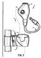
- the seat 32 has a latch for securing the lock head 16 into the cavity 60, as shown in Figs. 5 and 6.
- the latch precludes the need for gravity to hold the lock head 16 in the cavity 60, so that various orientations of the bracket 12 are possible.
- An exemplary latch includes an arm 72 in four sections. The lower end of the spring section 74 is anchored to the bracket 12, as at 76. Extending at about 90° from the upper end of the spring section 74 is an offset section 78, which offsets the knob section 80 from the spring section 74. Extending in the opposite direction from the offset section 78 is a tongue 82.
- the arm 72 is positioned so that it can flex between a latched position and an unlatched position. In the latched position, the tongue 82 extends into the cavity 60. In the unlatched position, the tongue 82 does not extend into the cavity 60.
- the spring section 74 biases the arm 72 to the latched position, so that manual force is needed to move the arm 72 to the unlatched position. When the manual force is removed, the arm 72 returns to the latched position.
- the tongue 82 fits into a groove 88 in the lock head 16.
- the upper surface of the tongue 82 is curved downwardly, as at 84, so that the arm 72 is pushed out of the way when the lock head 16 is being inserted into the cavity 60.
- the arm 72 snaps back so that the tongue 82 is in the groove 88.
- the lower surface of the tongue 82 and the lower surface of the groove 88 are flat so that the lock head 16 cannot be pulled from the cavity 60.
- the lock head 16 is removed from the cavity 60 by manually pulling back on the knob 80 so that the tongue 82 comes out of the groove 88, and then pulling the lock head 16 from the cavity 60.
- the arm 72 can be located anywhere around the circumference of the seat 32. Most preferably, however, it is located in the section of the seat nearest the attachment 30. This gives the most support and protection to the arm 72. Because the arm 72 has a protruding knob 80 and is somewhat flexible, it would be vulnerable to having an external object catch on it and snap it off if not protected.
- the bracket 12 is composed of a rigid plastic, such as ABS, nylon 6/6, or glass-filled nylon 6/6.
Landscapes
- Engineering & Computer Science (AREA)
- Mechanical Engineering (AREA)
- Flexible Shafts (AREA)
- Motorcycle And Bicycle Frame (AREA)
Applications Claiming Priority (4)
| Application Number | Priority Date | Filing Date | Title |
|---|---|---|---|
| US20638 | 1987-03-02 | ||
| US2063898A | 1998-02-09 | 1998-02-09 | |
| US09/161,932 US6016673A (en) | 1998-02-09 | 1998-09-28 | Cable lock and bracket |
| US161932 | 1998-09-28 |
Publications (2)
| Publication Number | Publication Date |
|---|---|
| EP0934869A2 true EP0934869A2 (de) | 1999-08-11 |
| EP0934869A3 EP0934869A3 (de) | 2001-01-17 |
Family
ID=26693683
Family Applications (1)
| Application Number | Title | Priority Date | Filing Date |
|---|---|---|---|
| EP19990300105 Withdrawn EP0934869A3 (de) | 1998-02-09 | 1999-01-06 | Halterung für ein Fahrradschloss |
Country Status (3)
| Country | Link |
|---|---|
| US (1) | US6016673A (de) |
| EP (1) | EP0934869A3 (de) |
| TW (1) | TW415493U (de) |
Cited By (4)
| Publication number | Priority date | Publication date | Assignee | Title |
|---|---|---|---|---|
| EP1748131A3 (de) * | 2005-07-25 | 2008-07-16 | ABUS August Bremicker Söhne KG | Sicherungssystem, vorzugsweise ein Fahrradschloss |
| EP3109141A1 (de) * | 2015-06-22 | 2016-12-28 | ABUS August Bremicker Söhne KG | Halterung |
| CN108974191A (zh) * | 2018-06-19 | 2018-12-11 | 苏州爱盟机械有限公司 | 智能锁的锁座安装结构 |
| DE102013102009B4 (de) * | 2012-03-08 | 2021-05-06 | FAHRER Berlin GmbH | Schlosshalter |
Families Citing this family (16)
| Publication number | Priority date | Publication date | Assignee | Title |
|---|---|---|---|---|
| US6321961B1 (en) * | 1999-09-03 | 2001-11-27 | Kryptonite Corporation | Bicycle retention bracket |
| US6619084B2 (en) * | 2001-08-08 | 2003-09-16 | Lambert Kuo | Lock assembly for a cycle |
| US20080276664A1 (en) * | 2007-05-11 | 2008-11-13 | Vulcan Sports Co., Ltd. | Steel cable fastenable to a lock |
| USD685132S1 (en) * | 2009-08-24 | 2013-06-25 | Yun Ying Lee | Hair dryer stand |
| AU332070S (en) * | 2010-01-28 | 2010-08-04 | Knog Pty Ltd | Cable lock |
| US8132437B1 (en) * | 2011-01-20 | 2012-03-13 | Sinox Lock (Kushan) Co. Ltd. | Bicycle lock |
| US9079626B2 (en) | 2011-05-25 | 2015-07-14 | Robert David Zuraski | Portable lock mounting assemblies |
| EP3354546B1 (de) | 2011-05-25 | 2020-12-23 | Schlage Lock Company LLC | Schlossbefestigungsanordnungen für transportvorrichtungen |
| GB2516460A (en) * | 2013-07-22 | 2015-01-28 | Plus 8 Ind Ltd | A security device |
| WO2016028193A2 (ru) * | 2014-08-18 | 2016-02-25 | Роман Евгеньевич ВОЛОСЕВИЧ | Запирающее устройство биометрическое |
| TWI537163B (zh) * | 2015-07-30 | 2016-06-11 | 昇詠鎖業有限公司 | 多用途自行車鎖結構 |
| DE102016115913A1 (de) | 2016-08-26 | 2018-03-01 | Kenner Gmbh Cnc-Komplettbearbeitung | Vorrichtung zum Festlegen eines Schlosses an einem Verkehrsmittel oder einem Transportmittel |
| US10196837B2 (en) | 2016-09-01 | 2019-02-05 | Schlage Lock Company Llc | Ceramic spine security cable |
| USD894050S1 (en) * | 2019-02-10 | 2020-08-25 | Lyft, Inc. | Fender with integrated lock |
| US11019812B1 (en) * | 2020-04-28 | 2021-06-01 | David Glassberg | Tackle container and kit |
| US20250276750A1 (en) * | 2024-02-29 | 2025-09-04 | Ino Vision Ltd. | Bicycle lock carrier assembly |
Family Cites Families (22)
| Publication number | Priority date | Publication date | Assignee | Title |
|---|---|---|---|---|
| US2471825A (en) * | 1946-03-06 | 1949-05-31 | Long Margaret | Electric razor holder |
| US3286762A (en) * | 1964-12-03 | 1966-11-22 | Robertshaw Controls Co | Combination pilot burner and thermocouple mount |
| US4155231A (en) * | 1977-04-29 | 1979-05-22 | Kbl Corporation | Bicycle lock and bracket |
| US4736921A (en) * | 1985-05-24 | 1988-04-12 | Kbl Corporation | Clamp for holding bicycle lock |
| US4696447A (en) * | 1986-05-12 | 1987-09-29 | Dennis Strecker | Blow dryer holding device |
| US4811577A (en) * | 1986-07-02 | 1989-03-14 | Webster Noel E | Portable locking device |
| US5255546A (en) * | 1988-05-31 | 1993-10-26 | Striders, Inc. | Apparatus for inflating inflatable articles and securing mobile articles to other objects |
| DE3913471A1 (de) * | 1988-09-07 | 1990-03-15 | Winkhaus Fa August | Halterung fuer ein langbuegelschloss |
| DE9001015U1 (de) * | 1990-01-30 | 1990-04-05 | Aug. Winkhaus GmbH & Co KG, 4404 Telgte | Halterungseinrichtung zur Halterung eines Langbügelschlosses an einem Träger |
| US5194717A (en) * | 1990-10-18 | 1993-03-16 | Tecumseh Products Company | Bracket for mounting a crankcase heater |
| US5291765A (en) * | 1992-12-16 | 1994-03-08 | Gary Hoisington | Bicycle lock bracket |
| US5386961A (en) * | 1993-04-26 | 1995-02-07 | Interseng Hardware Company L.T.D. | Multi-directional mounting unit for mounting a bicycle lock on a tubular frame |
| DE9313594U1 (de) * | 1993-09-08 | 1995-01-12 | Aug. Winkhaus Gmbh & Co Kg, 48291 Telgte | Kabelschloß, insbesondere für Zweiradfahrzeuge |
| US5405113A (en) * | 1994-01-24 | 1995-04-11 | Jaw; Chin-Woei | Bicycle padlock holder |
| USD365745S (en) | 1994-04-08 | 1996-01-02 | EASEC-Schloss-Production GmbH & Co. KG | Bicycle lock |
| DE19532383A1 (de) * | 1995-09-01 | 1997-03-06 | Winkhaus Fa August | Mitführbefestigung eines Zubehörteils an einem mobilen Objekt |
| DE19532933A1 (de) * | 1995-09-06 | 1997-03-13 | Bremicker Soehne Kg A | Schließvorrichtung |
| US5647520A (en) * | 1995-12-01 | 1997-07-15 | Kryptonite Corporation | Bicycle lock bracket with splines |
| DE29608913U1 (de) * | 1996-05-17 | 1996-10-02 | ABUS August Bremicker Söhne KG, 58300 Wetter | Schließvorrichtung |
| US5653365A (en) * | 1996-06-12 | 1997-08-05 | Simple Locksmith Co., Ltd. | Supporting bracket of lock for bicycle |
| US5761934A (en) * | 1996-10-22 | 1998-06-09 | Kuo; Li-Tsao | Cable lock and an universal hold-down support |
| US5718134A (en) * | 1996-12-13 | 1998-02-17 | Chang; Chin-Shu | Bicycle cable lock |
-
1998
- 1998-09-28 US US09/161,932 patent/US6016673A/en not_active Expired - Lifetime
- 1998-11-19 TW TW87219171U patent/TW415493U/zh not_active IP Right Cessation
-
1999
- 1999-01-06 EP EP19990300105 patent/EP0934869A3/de not_active Withdrawn
Non-Patent Citations (1)
| Title |
|---|
| None |
Cited By (6)
| Publication number | Priority date | Publication date | Assignee | Title |
|---|---|---|---|---|
| EP1748131A3 (de) * | 2005-07-25 | 2008-07-16 | ABUS August Bremicker Söhne KG | Sicherungssystem, vorzugsweise ein Fahrradschloss |
| DE102013102009B4 (de) * | 2012-03-08 | 2021-05-06 | FAHRER Berlin GmbH | Schlosshalter |
| EP3109141A1 (de) * | 2015-06-22 | 2016-12-28 | ABUS August Bremicker Söhne KG | Halterung |
| US10081404B2 (en) | 2015-06-22 | 2018-09-25 | ABUS August Bremicker Söhne KG | Holder |
| DE102015109997B4 (de) | 2015-06-22 | 2022-10-13 | ABUS August Bremicker Söhne Kommanditgesellschaft | Halterung |
| CN108974191A (zh) * | 2018-06-19 | 2018-12-11 | 苏州爱盟机械有限公司 | 智能锁的锁座安装结构 |
Also Published As
| Publication number | Publication date |
|---|---|
| US6016673A (en) | 2000-01-25 |
| TW415493U (en) | 2000-12-11 |
| EP0934869A3 (de) | 2001-01-17 |
Similar Documents
| Publication | Publication Date | Title |
|---|---|---|
| US6016673A (en) | Cable lock and bracket | |
| US7267592B1 (en) | Latching system for an outboard motor cowl | |
| US6301940B1 (en) | Security hole fastening device | |
| US5154456A (en) | Security locking bracket apparatus for a portable computer | |
| US5934112A (en) | Locking gun rack system | |
| CA2690073C (en) | Secure mounting arrangements for a lock assembly | |
| WO1999058032A1 (en) | Mounting assembly | |
| US8245859B2 (en) | Equipment rack | |
| JP2968699B2 (ja) | ラッチ組立体 | |
| NZ255593A (en) | Conduit clamp unreleasable from support structure without release of conduit | |
| US4779434A (en) | Tailgate locking device | |
| US4938040A (en) | Securing device for surfboards | |
| US8974128B2 (en) | Retaining clip for camera mounting bracket | |
| US6739487B2 (en) | Vertically engageable carrier foot | |
| US5622399A (en) | Remote tie-off adaptor and snap hook attachment device | |
| US5669081A (en) | Self-locking toilet seat cover | |
| WO1999050132A1 (en) | Locking device for a helmet | |
| WO1995001902A1 (en) | Bicycle seat security ring | |
| US7232281B2 (en) | Motorcycle transporting device | |
| US6401504B1 (en) | Threaded hole locking device | |
| US6382570B1 (en) | Adjustable hangar | |
| US5425525A (en) | Anti-theft device | |
| US4790577A (en) | Door push-bar lock-out retainer | |
| GB2347458A (en) | Vehicle bonnet lock device | |
| JP2002523655A (ja) | 防犯錠止機構 |
Legal Events
| Date | Code | Title | Description |
|---|---|---|---|
| PUAI | Public reference made under article 153(3) epc to a published international application that has entered the european phase |
Free format text: ORIGINAL CODE: 0009012 |
|
| AK | Designated contracting states |
Kind code of ref document: A2 Designated state(s): AT BE CH CY DE DK ES FI FR GB GR IE IT LI LU MC NL PT SE |
|
| AX | Request for extension of the european patent |
Free format text: AL;LT;LV;MK;RO;SI |
|
| PUAL | Search report despatched |
Free format text: ORIGINAL CODE: 0009013 |
|
| AK | Designated contracting states |
Kind code of ref document: A3 Designated state(s): AT BE CH CY DE DK ES FI FR GB GR IE IT LI LU MC NL PT SE |
|
| AX | Request for extension of the european patent |
Free format text: AL;LT;LV;MK;RO;SI |
|
| AKX | Designation fees paid | ||
| REG | Reference to a national code |
Ref country code: DE Ref legal event code: 8566 |
|
| STAA | Information on the status of an ep patent application or granted ep patent |
Free format text: STATUS: THE APPLICATION IS DEEMED TO BE WITHDRAWN |
|
| 18D | Application deemed to be withdrawn |
Effective date: 20010718 |