EP0934868A2 - Body handling and assembly system - Google Patents
Body handling and assembly system Download PDFInfo
- Publication number
- EP0934868A2 EP0934868A2 EP99200349A EP99200349A EP0934868A2 EP 0934868 A2 EP0934868 A2 EP 0934868A2 EP 99200349 A EP99200349 A EP 99200349A EP 99200349 A EP99200349 A EP 99200349A EP 0934868 A2 EP0934868 A2 EP 0934868A2
- Authority
- EP
- European Patent Office
- Prior art keywords
- handling means
- accordance
- hanger
- grasping
- jaws
- Prior art date
- Legal status (The legal status is an assumption and is not a legal conclusion. Google has not performed a legal analysis and makes no representation as to the accuracy of the status listed.)
- Granted
Links
Images

Classifications
-
- B—PERFORMING OPERATIONS; TRANSPORTING
- B62—LAND VEHICLES FOR TRAVELLING OTHERWISE THAN ON RAILS
- B62D—MOTOR VEHICLES; TRAILERS
- B62D65/00—Designing, manufacturing, e.g. assembling, facilitating disassembly, or structurally modifying motor vehicles or trailers, not otherwise provided for
Definitions
- the present invention relates to a station and a body assembly system.
- These systems generally include a plurality of handling pallets each provided with centering pins on which is positioned the lower surface of a preassembled body made up of a series of pressed sheet metal panels.
- the pallet comprises a series of locking members for holding the body in a predetermined position.
- the pallet comprises series of reference pins fixed to the pallet structure and on which the body is rested.
- a handling system supports the pallets and moves them along a line which passes through one or more welding stations.
- Each welding station includes a series of programmable robots which perform the welding operations and fixed equipment which hold the members transported on the pallet in position during welding.
- the body positioning accuracy can vary also. This can influence both the quality of the welding and repeatability with harmful effects on final product quality.
- Another disadvantage is that the pallet handling and repositioning devices must be kept in good condition to prevent pallet positioning accuracy variation.
- the general purpose of the present invention is to obviate the above mentioned drawbacks by making available an assembly system and stations in which pallet production accuracy would not influence the positioning accuracy of the bodies born on the pallets.
- a further purpose is to make available an assembly system and stations which would not need accurate pallet or handling system positioning and would allow variability between individual pallets and handling systems.
- Another purpose is to avoid the need for continuously keeping assembly system components such as the pallet or handling systems in optimal condition to ensure body positioning accuracy in the stations.
- a body assembly system with work stations and body handling means between work stations comprising reference members mounted in a adaptable manner on handling means for supporting the body on the handling means during movement between work stations and grasping devices mounted in the work stations for grasping the reference members and positioning them accurately while disengaging them temporarily from the handling means in such a manner as to position the body supported on the reference members accurately in the station space.
- Fig. 1 shows a partial view of a system indicated as a whole by reference number 10 comprising a handling system made up of a rail 11 on which run conveyors or handling means 12.
- the conveyors or self-movers comprise motor drives 13 running along the rail and bearing hangers 14 for support of bodies 15 to be processed (typically welding).
- the hanger conveyors carry the bodies between a plurality of work stations or cells of which one indicated by reference number 16 is shown in Fig. 1.
- the hanger 14 comprises supports or reference members 17 on which is rested the body to be handled.
- the supports 17 are placed on four arms 18 generally L-shaped and arranged in pairs at the front and rear. Each pair is supported by a respective overturned T beam 19 having an arm 20 for fixing to a longitudinal upper beam 21 of the self-mover.
- the supports 17 are positioned in an adaptable manner on the hanger.
- Holding and reference devices 27 are located in the work station 16 for grasping the supports 17 of the body and moving them from the rest position on the hanger to a position (accurately determined by the holding devices) that is for accurate positioning of the body in the work station.
- the supports 17 are supporting for handling with no need of great positioning accuracy.
- the supports are disengaged from the handling unit and positioned accurately by means of devices 27 in the station to become accurate positioning supports for the body with respect to the station.
- each support 17 includes a positioning pin 22 which is vertical and has its upper end tapered (e.g. conical) designed to fit accurately in an appropriate reference seat 23 in the body 15.
- the part of the pin which is received in the seat can be e.g. cylindrical or lozenge-shaped.
- a hemispherical fifth wheel 24 for adaptable support in a complementary seat 25 present in the respective arm 18 of the hanger.
- the top surface of the fifth wheel provides a plane or disk 34 for supporting the body.
- the pin 22 continues downward beyond the set 25 and ends with a ball 26 which defines spherical grasping surfaces.
- the fifth wheel 24 is rested in the seat 25 and the body is supported on the hanger.
- each jaw comprises rollers or bearings for contact with the ball 26 for accurately positioning its center.
- each jaw comprises a pair of rollers or bearings 29 and 30 arranged in a vertical plane and two bearings or rollers 31, 32 arranged in a horizontal plane.
- the bearings 29, 30 are arranged over and under the equatorial diameter of the ball and the bearings 31, 32 are arranged side by side in intermediate position between the rollers or bearings 29, 30.
- the jaws To accurately lock rotation of the ball 26 also and thus accurately position the point of the pin 22 the jaws have ends 33 for grasping the cylindrical body of the pin and constitute reaction means for angular positioning of the reference member 17 around the center of the ball to define the axis.
- the handling system When required the handling system will stop the hanger inside a cell 16 with a positioning tolerance common to handling systems with self-mover, for example +-20mm so that the balls 26 are inside the area circumscribed by the jaws of the locking devices 27.
- the pins 22 are thus freed from the hanger and positioned with the desired accuracy for the operations to be performed in the cell.
- handling means could be formed differently from that shown depending on specific requirements.
- Each grasping device could have two or three jaws.
Abstract
Description
- The present invention relates to a station and a body assembly system.
- In the prior art there are systems and assembly stations for welding automotive vehicle bodies and the like in which programmable robots apply welding spots in formation stations (termed 'geometry') and in subsequent completion stations for finishing.
- These systems generally include a plurality of handling pallets each provided with centering pins on which is positioned the lower surface of a preassembled body made up of a series of pressed sheet metal panels. The pallet comprises a series of locking members for holding the body in a predetermined position. Usually the pallet comprises series of reference pins fixed to the pallet structure and on which the body is rested. A handling system supports the pallets and moves them along a line which passes through one or more welding stations.
- Each welding station includes a series of programmable robots which perform the welding operations and fixed equipment which hold the members transported on the pallet in position during welding.
- One disadvantage of the systems described is that the body is positioned on the pallet to be referred to it accurately. The pallet in turn must be positioned accurately with respect to the fixed equipment. As a result the body is positioned with respect to the fixed equipment indirectly through the pallet structure. The necessity of having to provide very accurate pallet structures involves high costs since the pallets are used in large quantities.
- In addition, as the dimensional accuracy of the pallets can vary the body positioning accuracy can vary also. This can influence both the quality of the welding and repeatability with harmful effects on final product quality.
- Another disadvantage is that the pallet handling and repositioning devices must be kept in good condition to prevent pallet positioning accuracy variation.
- The general purpose of the present invention is to obviate the above mentioned drawbacks by making available an assembly system and stations in which pallet production accuracy would not influence the positioning accuracy of the bodies born on the pallets. In addition a further purpose is to make available an assembly system and stations which would not need accurate pallet or handling system positioning and would allow variability between individual pallets and handling systems. Another purpose is to avoid the need for continuously keeping assembly system components such as the pallet or handling systems in optimal condition to ensure body positioning accuracy in the stations.
- In view of these purposes in accordance with the present invention it is sought to provide a body assembly system with work stations and body handling means between work stations comprising reference members mounted in a adaptable manner on handling means for supporting the body on the handling means during movement between work stations and grasping devices mounted in the work stations for grasping the reference members and positioning them accurately while disengaging them temporarily from the handling means in such a manner as to position the body supported on the reference members accurately in the station space.
- To clarify the explanation of the innovative principles of the present invention and its advantages compared with the prior art there is described below with the aid of the annexed drawings a possible embodiment thereof by way of non-limiting example applying said principles. In the drawings:
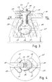
- Fig. 1 shows a diagrammatic perspective view of a system in accordance with the present invention comprising a work cell or station,
- Fig. 2 shows a partial front elevation view of the work cell of Fig. 1,
- Fig. 3 shows an elevation view of a reference pin and associated locking unit, and
- Fig. 4 is a plan view of the reference pin and the associated locking unit of Fig. 3.
- With reference to the figures, Fig. 1 shows a partial view of a system indicated as a whole by
reference number 10 comprising a handling system made up of arail 11 on which run conveyors orhandling means 12. The conveyors or self-movers comprisemotor drives 13 running along the rail and bearinghangers 14 for support ofbodies 15 to be processed (typically welding). The hanger conveyors carry the bodies between a plurality of work stations or cells of which one indicated byreference number 16 is shown in Fig. 1. - A similar handling system is known in its general lines and therefore will not be further described or shown. In accordance with the innovative principles of the present invention the
hanger 14 comprises supports orreference members 17 on which is rested the body to be handled. As an example thesupports 17 are placed on fourarms 18 generally L-shaped and arranged in pairs at the front and rear. Each pair is supported by a respectiveoverturned T beam 19 having anarm 20 for fixing to a longitudinalupper beam 21 of the self-mover. - As clarified below in accordance with the present invention the
supports 17 are positioned in an adaptable manner on the hanger. Holding andreference devices 27 are located in thework station 16 for grasping thesupports 17 of the body and moving them from the rest position on the hanger to a position (accurately determined by the holding devices) that is for accurate positioning of the body in the work station. In this manner during moving of the body between work stations thesupports 17 are supporting for handling with no need of great positioning accuracy. During the operation phase in the station the supports are disengaged from the handling unit and positioned accurately by means ofdevices 27 in the station to become accurate positioning supports for the body with respect to the station. - As may be seen better in figures 2 and 3 in the preferred embodiment each
support 17 includes apositioning pin 22 which is vertical and has its upper end tapered (e.g. conical) designed to fit accurately in anappropriate reference seat 23 in thebody 15. The part of the pin which is received in the seat can be e.g. cylindrical or lozenge-shaped. - Just under the cylindrical or lozenge-shaped part of the
reference pin 22 is mounted a hemisphericalfifth wheel 24 for adaptable support in acomplementary seat 25 present in therespective arm 18 of the hanger. The top surface of the fifth wheel provides a plane ordisk 34 for supporting the body. Thepin 22 continues downward beyond theset 25 and ends with aball 26 which defines spherical grasping surfaces. During handling operations thefifth wheel 24 is rested in theseat 25 and the body is supported on the hanger. - The
holding devices 27 are provided with movable jaws 28 (powered for moving between the broken line position and the solid line position of Fig. 3) which are designed to close around the lower spherical end of arespective support 17 for raising the support from theseat 25 and positioning it accurately with respect to the work station. - For this purpose each jaw comprises rollers or bearings for contact with the
ball 26 for accurately positioning its center. In the preferred embodiment shown each jaw comprises a pair of rollers orbearings rollers 31, 32 arranged in a horizontal plane. For example thebearings bearings 31, 32 are arranged side by side in intermediate position between the rollers orbearings - To accurately lock rotation of the
ball 26 also and thus accurately position the point of thepin 22 the jaws haveends 33 for grasping the cylindrical body of the pin and constitute reaction means for angular positioning of thereference member 17 around the center of the ball to define the axis. - During operation of the system when the locking devices are in open position the hanger with the
reference pins 17 is free to pass through the work station or cell. - When required the handling system will stop the hanger inside a
cell 16 with a positioning tolerance common to handling systems with self-mover, for example +-20mm so that theballs 26 are inside the area circumscribed by the jaws of thelocking devices 27. - Before starting the body work cycle the locking and positioning
devices holding devices 27 close thejaws 28 on the balls of therespective pins 17 to bring thebearings 29, 31 against the balls. The closing jaws cause the bearings to roll on the surface of the balls which rise until they are positioned with the desired accuracy inside the locking devices. Theends 33 of the jaws lock the pins to prevent rotation of the ball. - The bearings eliminate drag wear.
- The
pins 22 are thus freed from the hanger and positioned with the desired accuracy for the operations to be performed in the cell. - At this point the work equipment such as e.g. welding robots or other (not shown since of any known type readily imaginable for one skilled in the art) can begin their work on the body which will always be accurately located in the same position.
- It is now clear that the preset purposes have been achieved by providing an installation with an accurate positioning system not dependent on the construction and positioning tolerances of the handling means.
- Naturally the above description of an embodiment applying the innovative principles of the present invention is given by way of non-limiting example of said principles within the scope of the exclusive right claimed here.
- For example the handling means could be formed differently from that shown depending on specific requirements. Each grasping device could have two or three jaws.
Claims (11)
- Body assembly system with work stations and body handling means between work stations comprising:reference members (17) mounted in an adaptable manner on handling means for supporting the body on the handling means during movement between work stations, andgrasping devices (27) mounted in the work stations for grasping the reference members (17) and positioning them accurately while disengaging them temporarily from the handling means in such a manner as to accurately position the body supported on the reference members in the station space.
- System in accordance with claim 1 characterized in that the reference members (17) comprise a supporting zone for the body (34) above and an intermediate area (24) for support of the member on the handling means and a lower zone with spherical surface (26) with the grasping device (27) comprising jaws (28) moving between an open position for free passage of the reference member and a closed position for grasping the spherical surface for raising the intermediate support zone (24) and accurate positioning of the spherical surface curvature center with the jaws also comprising reaction means (33) acting against the reference members upon closing of the jaws for accurate angular positioning of the member (17) around the spherical surface center.
- System in accordance with claim 2 characterized in that the body support zone comprises a vertical cylindrical part (22) with tapered end for passage into a purposeful seat (23) in the body and a horizontal disk (34) for support of the body.
- System in accordance with claim 2 characterized in that the intermediate support zone for the member on the handling means comprises a fifth wheel (24) which is hemispherical below and rests in a complementary seat (25) in the handling means.
- System in accordance with claim 2 characterized in that the reaction means of the jaws comprise ends (33) of the jaws which rest on the part of the member (17) which connects the lower grasping zone (26) and the intermediate support zone (24).
- System in accordance with claim 2 characterized in that the jaws (28) have bearings (29-32) for contact with the spherical surface.
- System in accordance with claim 6 characterized in that for each jaw the bearings are two in a horizontal plane and two in a vertical plane.
- System in accordance with claim 2 characterized in that the reference member is made up of a pin arranged vertically with its upper end for support of the body and its lower end spherical for its grasping by the grasping devices.
- System in accordance with claim 1 characterized in that the handling means comprise a hanger (14) suspended from a self-mover carriage (13) running on a suspended rail (11) with the hanger having horizontal arms (18) at the ends of which are located the reference members (17) on which rests the body.
- Body welding system including a hanger for movement of a preassembled body to a work cell comprising:a series of horizontal arms (18) connected to the hanger and suspended through the hanger over a support surface (16),reference pins (17) operationally mounted on said horizontal arms (18) in an adaptable manner to support the body in spatial relation with the hanger,special clamps (27) mounted on the support surface to accurately position and release the reference pins (17) with respect to the support surface independently of the handling hanger to directly position the body in the work cell.
- System in accordance with claim 10 characterized in that the pins (17) have their upper part pointed or lozenge-shaped and ending in a supporting plane (34) for the body and a cylindrical lower part connected to a spherical part (26) and the special clamps comprise jaws (28) moving between an open and a closed position to lock or release through contact with bearings the lower part of the pins which directly position the body in the work cell accurately.
Applications Claiming Priority (5)
| Application Number | Priority Date | Filing Date | Title |
|---|---|---|---|
| ITMI980254 | 1998-02-11 | ||
| IT98MI000254A IT1298222B1 (en) | 1998-02-11 | 1998-02-11 | SYSTEM FOR TRANSPORT AND ASSEMBLY OF BODIES |
| CA002277692A CA2277692A1 (en) | 1998-02-11 | 1999-07-14 | Body handling and assembly system |
| BR9902899-9A BR9902899A (en) | 1998-02-11 | 1999-07-27 | Body mounting and steering system |
| CN99111992.4A CN1283579A (en) | 1998-02-11 | 1999-08-04 | Transport and mounting system of car body |
Publications (3)
| Publication Number | Publication Date |
|---|---|
| EP0934868A2 true EP0934868A2 (en) | 1999-08-11 |
| EP0934868A3 EP0934868A3 (en) | 1999-12-15 |
| EP0934868B1 EP0934868B1 (en) | 2003-05-02 |
Family
ID=27425290
Family Applications (1)
| Application Number | Title | Priority Date | Filing Date |
|---|---|---|---|
| EP99200349A Expired - Lifetime EP0934868B1 (en) | 1998-02-11 | 1999-02-06 | Body handling and assembly system |
Country Status (8)
| Country | Link |
|---|---|
| US (1) | US6196372B1 (en) |
| EP (1) | EP0934868B1 (en) |
| CN (1) | CN1283579A (en) |
| BR (1) | BR9902899A (en) |
| CA (1) | CA2277692A1 (en) |
| DE (1) | DE69907288T2 (en) |
| ES (1) | ES2195504T3 (en) |
| IT (1) | IT1298222B1 (en) |
Cited By (1)
| Publication number | Priority date | Publication date | Assignee | Title |
|---|---|---|---|---|
| DE10005413A1 (en) * | 2000-02-08 | 2001-08-16 | Eisenmann Kg Maschbau | Transport system for rough assembly of vehicle bodies has positioning devices independent of rail system, working passively without their own drive, activated alone by movement of wagon |
Families Citing this family (20)
| Publication number | Priority date | Publication date | Assignee | Title |
|---|---|---|---|---|
| DE19809515C2 (en) * | 1998-03-05 | 2002-10-31 | Daimler Chrysler Ag | Method and device for applying self-adhesive protective film to bodies |
| IT246948Y1 (en) * | 1999-12-17 | 2002-04-10 | Fata Group S P A | MACHINING SYSTEM WITH LOCKING DEVICE AND CENTERING DISCS IN MACHINING STATIONS. |
| JP3976224B2 (en) * | 2000-09-22 | 2007-09-12 | 本田技研工業株式会社 | Overhead conveyor |
| US6505726B1 (en) * | 2001-06-29 | 2003-01-14 | Valiant Corporation | Soft touch lifter |
| JP3983183B2 (en) * | 2003-02-18 | 2007-09-26 | トヨタ車体株式会社 | Transport equipment |
| DE10358365A1 (en) * | 2003-12-12 | 2005-07-28 | Bosch Rexroth Ag | Positioning unit and transport system with positioning device |
| FR2896300A1 (en) * | 2006-01-19 | 2007-07-20 | Abb Mc Soc Par Actions Simplif | Adjustable support for workpieces has tubular base, in which spindle is mounted, nut mounted at lower end of upper section of support cooperating with spindle to allow upper section to be raised and lowered |
| DE102006046050B4 (en) * | 2006-09-28 | 2021-04-08 | Bayerische Motoren Werke Aktiengesellschaft | Method for aligning a vehicle body-in-white |
| JP4538820B2 (en) * | 2008-02-05 | 2010-09-08 | 株式会社ダイフク | Friction drive trolley conveyor |
| JP4562008B2 (en) * | 2008-02-14 | 2010-10-13 | 株式会社ダイフク | Hanging conveyor |
| DE102009041355A1 (en) | 2009-09-15 | 2010-05-06 | Daimler Ag | Body for passenger car, has support part i.e. side sill, in which receiving device with front and rear receiving consoles for conveying device i.e. hanger conveyor, is set, where receiving consoles are fastened to support tail from outside |
| PL2298631T3 (en) * | 2009-09-21 | 2013-03-29 | Siemens Ag | Transport device for a vehicle assembly device |
| US8839507B2 (en) | 2009-12-15 | 2014-09-23 | Comau, Inc. | Remote locking apparatus for securing a vehicle body to a vehicle body support |
| DE102010045010A1 (en) * | 2010-09-10 | 2012-03-15 | Eisenmann Ag | Transport unit and conveyor system for transporting vehicle bodies and system for the treatment of vehicle bodies |
| ITTO20120241A1 (en) * | 2012-03-19 | 2013-09-20 | Cpm S P A | PLANT TO ASSEMBLE MECHANICAL PARTS ON BODIES OF VEHICLES |
| CN104891102B (en) * | 2014-06-20 | 2017-06-16 | 广东德信模钢实业有限公司 | A kind of conveying device on automatic production line |
| CN108945165B (en) * | 2018-07-16 | 2020-08-25 | 北京福田戴姆勒汽车有限公司 | Automobile body assembly fixture |
| IT201800009976A1 (en) * | 2018-10-31 | 2020-05-01 | Fca Italy Spa | POSITIONING SYSTEM FOR A MOBILE FRAME, ESPECIALLY A FRAME FOR SUPPORTING VEHICLE BODIES, IN A WORKING STATION |
| EP3789281B8 (en) * | 2019-09-04 | 2022-06-01 | Ford Global Technologies, LLC | Automatically operating vehicle body unloading system |
| CN114313960A (en) * | 2021-12-13 | 2022-04-12 | 深圳航天科技创新研究院 | Front axle four-wheel drive feeding clamp |
Citations (2)
| Publication number | Priority date | Publication date | Assignee | Title |
|---|---|---|---|---|
| JPS60191912A (en) * | 1984-03-13 | 1985-09-30 | Toyota Auto Body Co Ltd | Method and device for translocating article |
| EP0213033A1 (en) * | 1985-08-06 | 1987-03-04 | Graco France | Method and apparatus for controlling the displacement of a product in a section of a production line |
Family Cites Families (4)
| Publication number | Priority date | Publication date | Assignee | Title |
|---|---|---|---|---|
| JPH0780565B2 (en) * | 1987-08-07 | 1995-08-30 | 本田技研工業株式会社 | Work positioning device on the carrier |
| SE459081B (en) * | 1987-10-07 | 1989-06-05 | Atlas Copco Ab | PROCEDURE AND DEVICE FOR POSITIONING A NUMBER OF WORK ORGANIZATIONS RELATIVELY TO A CAR BODY |
| DE69001847T2 (en) * | 1989-03-28 | 1993-12-16 | Renault Automation | Device for assembling a body using positionable side tools. |
| US5191958A (en) * | 1991-02-01 | 1993-03-09 | Giddings & Lewis, Inc. | Automatic framing system |
-
1998
- 1998-02-11 IT IT98MI000254A patent/IT1298222B1/en active IP Right Grant
-
1999
- 1999-02-06 EP EP99200349A patent/EP0934868B1/en not_active Expired - Lifetime
- 1999-02-06 ES ES99200349T patent/ES2195504T3/en not_active Expired - Lifetime
- 1999-02-06 DE DE69907288T patent/DE69907288T2/en not_active Expired - Fee Related
- 1999-02-10 US US09/247,331 patent/US6196372B1/en not_active Expired - Fee Related
- 1999-07-14 CA CA002277692A patent/CA2277692A1/en not_active Abandoned
- 1999-07-27 BR BR9902899-9A patent/BR9902899A/en not_active Application Discontinuation
- 1999-08-04 CN CN99111992.4A patent/CN1283579A/en active Pending
Patent Citations (2)
| Publication number | Priority date | Publication date | Assignee | Title |
|---|---|---|---|---|
| JPS60191912A (en) * | 1984-03-13 | 1985-09-30 | Toyota Auto Body Co Ltd | Method and device for translocating article |
| EP0213033A1 (en) * | 1985-08-06 | 1987-03-04 | Graco France | Method and apparatus for controlling the displacement of a product in a section of a production line |
Non-Patent Citations (1)
| Title |
|---|
| PATENT ABSTRACTS OF JAPAN vol. 010, no. 040 (M-454), 18 February 1986 (1986-02-18) & JP 60 191912 A (TOYOTA SHIYATAI KK), 30 September 1985 (1985-09-30) * |
Cited By (2)
| Publication number | Priority date | Publication date | Assignee | Title |
|---|---|---|---|---|
| DE10005413A1 (en) * | 2000-02-08 | 2001-08-16 | Eisenmann Kg Maschbau | Transport system for rough assembly of vehicle bodies has positioning devices independent of rail system, working passively without their own drive, activated alone by movement of wagon |
| US6604622B2 (en) | 2000-02-08 | 2003-08-12 | Eisenmann Maschinenbau Kg | Transport system used in body shell assembly of vehicle bodies |
Also Published As
| Publication number | Publication date |
|---|---|
| DE69907288D1 (en) | 2003-06-05 |
| CA2277692A1 (en) | 2001-01-14 |
| CN1283579A (en) | 2001-02-14 |
| DE69907288T2 (en) | 2004-04-08 |
| ES2195504T3 (en) | 2003-12-01 |
| US6196372B1 (en) | 2001-03-06 |
| EP0934868B1 (en) | 2003-05-02 |
| IT1298222B1 (en) | 1999-12-20 |
| ITMI980254A1 (en) | 1999-08-11 |
| EP0934868A3 (en) | 1999-12-15 |
| BR9902899A (en) | 2001-03-06 |
Similar Documents
| Publication | Publication Date | Title |
|---|---|---|
| US6196372B1 (en) | Body handling and assembly system | |
| JP2562280B2 (en) | Spot welding equipment for structures composed of pressed sheet metal elements | |
| US6250533B1 (en) | Clamping device for use in motor vehicle production lines and production line having such a clamping device | |
| US4751995A (en) | Jig for car body assembly | |
| US4256947A (en) | Car body welding assembly system | |
| US6474460B2 (en) | Processing plant with device for holding and centering bodies in processing stations | |
| US5397047A (en) | Device for spot welding of structures constituted by sheet metal elements, particularly motor-vehicle bodies | |
| US4930213A (en) | System for transferring vehicle body from a coating station to an assembly line and an overhead conveyor | |
| US20150118003A1 (en) | Vehicle frame turnover system and method | |
| US6766894B2 (en) | Suspension conveyance system | |
| KR101497030B1 (en) | Cart fixing device of hanger supply exhaust system for electron painting line | |
| CA2377037A1 (en) | Processing station on a motor vehicle assembly line | |
| US4799724A (en) | Gripping device | |
| KR20010011570A (en) | Body handling and assembly system | |
| MXPA99007380A (en) | Handling system and body assembly. | |
| JPH10273078A (en) | Automobile assembling line and automobile assembling method | |
| KR910002149B1 (en) | System for transferring vehicle body from a coating station to an assembly line and an overhead conveyor | |
| KR102007721B1 (en) | Device for carrying out vehicle wheel supportor | |
| JP2831032B2 (en) | Transport device using self-propelled body | |
| CN108544435B (en) | Centering table tool for total assembly of robot gripping apparatus | |
| JPH02250737A (en) | Positioning device for car body in flow production line | |
| JPH0234487A (en) | Carrying device using moving body | |
| JPS6228597Y2 (en) | ||
| US20030126740A1 (en) | Automotive framing system | |
| JPS6347675B2 (en) |
Legal Events
| Date | Code | Title | Description |
|---|---|---|---|
| PUAI | Public reference made under article 153(3) epc to a published international application that has entered the european phase |
Free format text: ORIGINAL CODE: 0009012 |
|
| AK | Designated contracting states |
Kind code of ref document: A2 Designated state(s): BE DE ES FR GB IT SE |
|
| AX | Request for extension of the european patent |
Free format text: AL;LT;LV;MK;RO;SI |
|
| RIN1 | Information on inventor provided before grant (corrected) |
Inventor name: ROSSI, CRISTIANO |
|
| PUAL | Search report despatched |
Free format text: ORIGINAL CODE: 0009013 |
|
| AK | Designated contracting states |
Kind code of ref document: A3 Designated state(s): AT BE CH CY DE DK ES FI FR GB GR IE IT LI LU MC NL PT SE |
|
| AX | Request for extension of the european patent |
Free format text: AL;LT;LV;MK;RO;SI |
|
| 17P | Request for examination filed |
Effective date: 20000526 |
|
| AKX | Designation fees paid |
Free format text: BE DE ES FR GB IT SE |
|
| RAP1 | Party data changed (applicant data changed or rights of an application transferred) |
Owner name: ADVANCED TECHNOLOGIES S.R.L. |
|
| 17Q | First examination report despatched |
Effective date: 20020404 |
|
| GRAH | Despatch of communication of intention to grant a patent |
Free format text: ORIGINAL CODE: EPIDOS IGRA |
|
| GRAH | Despatch of communication of intention to grant a patent |
Free format text: ORIGINAL CODE: EPIDOS IGRA |
|
| GRAA | (expected) grant |
Free format text: ORIGINAL CODE: 0009210 |
|
| AK | Designated contracting states |
Designated state(s): BE DE ES FR GB IT SE |
|
| PG25 | Lapsed in a contracting state [announced via postgrant information from national office to epo] |
Ref country code: IT Free format text: LAPSE BECAUSE OF FAILURE TO SUBMIT A TRANSLATION OF THE DESCRIPTION OR TO PAY THE FEE WITHIN THE PRESCRIBED TIME-LIMIT;WARNING: LAPSES OF ITALIAN PATENTS WITH EFFECTIVE DATE BEFORE 2007 MAY HAVE OCCURRED AT ANY TIME BEFORE 2007. THE CORRECT EFFECTIVE DATE MAY BE DIFFERENT FROM THE ONE RECORDED. Effective date: 20030502 |
|
| REG | Reference to a national code |
Ref country code: GB Ref legal event code: FG4D |
|
| REF | Corresponds to: |
Ref document number: 69907288 Country of ref document: DE Date of ref document: 20030605 Kind code of ref document: P |
|
| REG | Reference to a national code |
Ref country code: SE Ref legal event code: TRGR |
|
| PG25 | Lapsed in a contracting state [announced via postgrant information from national office to epo] |
Ref country code: GB Free format text: LAPSE BECAUSE OF NON-PAYMENT OF DUE FEES Effective date: 20040206 |
|
| PG25 | Lapsed in a contracting state [announced via postgrant information from national office to epo] |
Ref country code: SE Free format text: LAPSE BECAUSE OF NON-PAYMENT OF DUE FEES Effective date: 20040207 Ref country code: ES Free format text: LAPSE BECAUSE OF NON-PAYMENT OF DUE FEES Effective date: 20040207 |
|
| ET | Fr: translation filed | ||
| PLBE | No opposition filed within time limit |
Free format text: ORIGINAL CODE: 0009261 |
|
| STAA | Information on the status of an ep patent application or granted ep patent |
Free format text: STATUS: NO OPPOSITION FILED WITHIN TIME LIMIT |
|
| 26N | No opposition filed |
Effective date: 20040203 |
|
| PGFP | Annual fee paid to national office [announced via postgrant information from national office to epo] |
Ref country code: BE Payment date: 20040831 Year of fee payment: 6 |
|
| PG25 | Lapsed in a contracting state [announced via postgrant information from national office to epo] |
Ref country code: DE Free format text: LAPSE BECAUSE OF NON-PAYMENT OF DUE FEES Effective date: 20040901 |
|
| EUG | Se: european patent has lapsed | ||
| GBPC | Gb: european patent ceased through non-payment of renewal fee |
Effective date: 20040206 |
|
| PG25 | Lapsed in a contracting state [announced via postgrant information from national office to epo] |
Ref country code: FR Free format text: LAPSE BECAUSE OF NON-PAYMENT OF DUE FEES Effective date: 20041029 |
|
| REG | Reference to a national code |
Ref country code: FR Ref legal event code: ST |
|
| PG25 | Lapsed in a contracting state [announced via postgrant information from national office to epo] |
Ref country code: BE Free format text: LAPSE BECAUSE OF NON-PAYMENT OF DUE FEES Effective date: 20050228 |
|
| REG | Reference to a national code |
Ref country code: ES Ref legal event code: FD2A Effective date: 20040207 |
|
| BERE | Be: lapsed |
Owner name: *ADVANCED TECHNOLOGIES S.R.L. Effective date: 20050228 |
|
| BERE | Be: lapsed |
Owner name: *ADVANCED TECHNOLOGIES S.R.L. Effective date: 20050228 |