EP0933604A2 - Compressor control system for air conditioner - Google Patents
Compressor control system for air conditioner Download PDFInfo
- Publication number
- EP0933604A2 EP0933604A2 EP98124884A EP98124884A EP0933604A2 EP 0933604 A2 EP0933604 A2 EP 0933604A2 EP 98124884 A EP98124884 A EP 98124884A EP 98124884 A EP98124884 A EP 98124884A EP 0933604 A2 EP0933604 A2 EP 0933604A2
- Authority
- EP
- European Patent Office
- Prior art keywords
- power
- compressor
- controller
- source unit
- power source
- Prior art date
- Legal status (The legal status is an assumption and is not a legal conclusion. Google has not performed a legal analysis and makes no representation as to the accuracy of the status listed.)
- Granted
Links
Images


Classifications
-
- F—MECHANICAL ENGINEERING; LIGHTING; HEATING; WEAPONS; BLASTING
- F24—HEATING; RANGES; VENTILATING
- F24F—AIR-CONDITIONING; AIR-HUMIDIFICATION; VENTILATION; USE OF AIR CURRENTS FOR SCREENING
- F24F11/00—Control or safety arrangements
- F24F11/30—Control or safety arrangements for purposes related to the operation of the system, e.g. for safety or monitoring
- F24F11/32—Responding to malfunctions or emergencies
- F24F11/37—Resuming operation, e.g. after power outages; Emergency starting
-
- F—MECHANICAL ENGINEERING; LIGHTING; HEATING; WEAPONS; BLASTING
- F25—REFRIGERATION OR COOLING; COMBINED HEATING AND REFRIGERATION SYSTEMS; HEAT PUMP SYSTEMS; MANUFACTURE OR STORAGE OF ICE; LIQUEFACTION SOLIDIFICATION OF GASES
- F25B—REFRIGERATION MACHINES, PLANTS OR SYSTEMS; COMBINED HEATING AND REFRIGERATION SYSTEMS; HEAT PUMP SYSTEMS
- F25B49/00—Arrangement or mounting of control or safety devices
- F25B49/02—Arrangement or mounting of control or safety devices for compression type machines, plants or systems
- F25B49/022—Compressor control arrangements
-
- F—MECHANICAL ENGINEERING; LIGHTING; HEATING; WEAPONS; BLASTING
- F24—HEATING; RANGES; VENTILATING
- F24F—AIR-CONDITIONING; AIR-HUMIDIFICATION; VENTILATION; USE OF AIR CURRENTS FOR SCREENING
- F24F11/00—Control or safety arrangements
- F24F11/88—Electrical aspects, e.g. circuits
-
- H—ELECTRICITY
- H02—GENERATION; CONVERSION OR DISTRIBUTION OF ELECTRIC POWER
- H02P—CONTROL OR REGULATION OF ELECTRIC MOTORS, ELECTRIC GENERATORS OR DYNAMO-ELECTRIC CONVERTERS; CONTROLLING TRANSFORMERS, REACTORS OR CHOKE COILS
- H02P6/00—Arrangements for controlling synchronous motors or other dynamo-electric motors using electronic commutation dependent on the rotor position; Electronic commutators therefor
-
- F—MECHANICAL ENGINEERING; LIGHTING; HEATING; WEAPONS; BLASTING
- F25—REFRIGERATION OR COOLING; COMBINED HEATING AND REFRIGERATION SYSTEMS; HEAT PUMP SYSTEMS; MANUFACTURE OR STORAGE OF ICE; LIQUEFACTION SOLIDIFICATION OF GASES
- F25B—REFRIGERATION MACHINES, PLANTS OR SYSTEMS; COMBINED HEATING AND REFRIGERATION SYSTEMS; HEAT PUMP SYSTEMS
- F25B2600/00—Control issues
- F25B2600/02—Compressor control
- F25B2600/021—Inverters therefor
-
- Y—GENERAL TAGGING OF NEW TECHNOLOGICAL DEVELOPMENTS; GENERAL TAGGING OF CROSS-SECTIONAL TECHNOLOGIES SPANNING OVER SEVERAL SECTIONS OF THE IPC; TECHNICAL SUBJECTS COVERED BY FORMER USPC CROSS-REFERENCE ART COLLECTIONS [XRACs] AND DIGESTS
- Y02—TECHNOLOGIES OR APPLICATIONS FOR MITIGATION OR ADAPTATION AGAINST CLIMATE CHANGE
- Y02B—CLIMATE CHANGE MITIGATION TECHNOLOGIES RELATED TO BUILDINGS, e.g. HOUSING, HOUSE APPLIANCES OR RELATED END-USER APPLICATIONS
- Y02B30/00—Energy efficient heating, ventilation or air conditioning [HVAC]
- Y02B30/70—Efficient control or regulation technologies, e.g. for control of refrigerant flow, motor or heating
Landscapes
- Engineering & Computer Science (AREA)
- Mechanical Engineering (AREA)
- General Engineering & Computer Science (AREA)
- Physics & Mathematics (AREA)
- Thermal Sciences (AREA)
- Chemical & Material Sciences (AREA)
- Combustion & Propulsion (AREA)
- Power Engineering (AREA)
- Air Conditioning Control Device (AREA)
- Control Of Positive-Displacement Pumps (AREA)
Abstract
Description
- The present invention relates to a compressor control system for an air conditioner, and particularly to a compressor control system for an air conditioner which improves the control of the operation of a rotary type compressor.
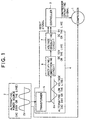
- According to most of generally-known air conditioners, air cooling/heating operation is carried out through a refrigeration cycle in which refrigerant alternately repeats condensation and evaporation, and in this refrigeration cycle the refrigerant is subjected to a high-temperature and high-pressure process and also compressed so that the refrigerant is provided with circulating power. A rotary or scroll type compressor is more frequently used to compress the refrigerant, and an induction motor or a DC motor is also more frequently used as an electric motor for these types of compressors. As one of these compressors is known a rotary type compressor 1 containing a single-phase induction motor which is driven by single-phase power as shown in Fig. 1.
- According to the induction motor, voltage is applied to plural coils while varying the phase of the voltage among the coils, thereby generating a rotating magnetic field, and a rotator is driven by the rotating magnetic field thus generated. In the case of the single-phase induction motor, the phase of the power source is single, and thus the voltage of the power source is applied to a primary coil while a voltage which is advanced in phase by inserting a capacitor in series is applied to an auxiliary coil, thereby generating a rotating magnetic field. This type of induction electric motor is known as a capacitor run motor type, and it is frequently used. The rotating magnetic field generated by the above capacitor run motor is more unstable than that generated by a three-phase induction motor based on a three-phase alternating power source, and the rotational force induced is more inhomogeneous.
- The single-phase induction electric motor will be described in more detail with reference to Fig. 1.
- The single-phase induction motor of the compressor 1 is supplied with an alternating voltage of about 200V from a
power source unit 2. The operation (start, stop) of the compressor 1 is controlled on the basis of an operating signal from acontroller 3. Thecontroller 3 controls not only the compressor 1, but also the other parts of an air conditioner. - The voltage from the
power source unit 2 is stabilized by a power converting device 4 comprising atransformer 5, a rectifying/smoothening circuit 6 and a voltage regulating circuit (constant-voltage circuit) 7, and the voltage thus stabilized is finally applied to thecontroller 3. When the voltage supply from thepower source unit 2 is intercepted due to a power failure, a reset signal is output from the voltage regulating circuit 7 of the power converting device 4 to thecontroller 3 to reset thecontroller 3, whereby an operating signal output from thecontroller 3 to the compressor 1 is extinguished. The operating signal is used to actuate the compressor 1. - However, since an electrolytic capacitor is used for the rectifying/smoothening
circuit 6 of the power converting device 4, the voltage supply from the voltage regulating circuit 7 to thecontroller 3 is continued for several hundreds msec from the occurrence of the power failure. Therefore, no reset signal is output from the voltage regulating circuit 7 to thecontroller 3, so that thecontroller 3 continues to operate and output the operating signal to the compressor 1. That is, the compressor 1 continues to rotate for the above time period. - Furthermore, the power supply from the
power source unit 2 to the compressor 1 is intercepted simultaneously with the occurrence of the power failure, and aroller 8A of the compressor 1 continues to rotate in a normal direction A by the inertial force and finally stops as shown in Fig. 2. When the power failure occurs in the process of compressing refrigerant, the compressed refrigerant applies its repulsive force acting in the opposite (reverse) direction B to the normal direction to theroller 8A of the compressor 1 under the compression process indicated by a two-dotted chain line of Fig. 2. - In Fig. 2,
reference numeral 8B represents a cylinder,reference numeral 8C represents a vane, andreference numerals cylinder 8B. - In the case of a long-term (several hundreds msec or more) power failure, when the compressor 1 is in the refrigerant compressing process at the time of occurrence of the power failure, with the repulsive force induced by the compressed refrigerant, the compressor 1 starts to rotate in the reverse direction due to the interception of the power supply to the compressor 1. However, during the long-term power failure, the voltage supply from the voltage regulating circuit 7 to the
controller 3 is intercepted, and thus the reset signal is output from the voltage regulating circuit 7 to thecontroller 3 to reset thecontroller 3, so that the operating signal from thecontroller 3 to the compressor 1 is extinguished. Therefore, the reverse rotation of the compressor 1 is stopped. - On the other hand, in the case of a short-term (from several tens (about 40) msec to several hundreds msec or less) power failure, when the compressor 1 is in the refrigerant-compressing process at the time of occurrence of the power failure, the repulsive force induced by the compressed refrigerant causes the compressor 1 to start rotating in the reverse direction, however, the voltage supply from the voltage regulating circuit 7 to the
controller 3 still continues during this power failure, so that no reset signal is output from the voltage regulating circuit 7 to thecontroller 3, so that thecontroller 3 continues to output the operating signal to the compressor 1. Accordingly, when the power is restored after the short-term power failure, the single-phase induction motor of the compressor 1 generates unstable rotational magnetic field, and the rotational force in the normal direction is weak, so that the compressor 1 continues to rotate in the reverse direction. - The reverse rotation of the compressor 1 causes increase of the pressure in the compressor 1 and heating, and lubricant oil in the compressor 1 is deteriorated, finally resulting in failure of the compressor 1.
- Usually, the compressor 1 is provided with a device for monitoring the pressure at the exit thereof or the operation current thereof to prevent the failure of the compressor 1. In the reverse rotation state of the compressor, there is little variation from the normal state in the pressure at the exit and the operation current, so that the reverse rotation phenomenon cannot be detected by using the monitoring device described above. Further, even when a thermostat for detecting the increase of temperature or the like is provided to the coil of the electric motor of the compressor, it takes long time until the temperature of the coil increases to a temperature at which the thermostat operates, and thus the compressor 1 may fail due to the reverse rotation of the compressor 1.
- Besides, when the reset signal is output from the voltage regulating circuit 7 of the power converting device 4 to the
controller 3, depending on the power occurrence manner of thepower source unit 2, some dispersion may occur in reset time in which the reset of thecontroller 3 is completed, and particularly when the voltage of thepower source unit 2 is reduced, the voltage regulating circuit 7 may erroneously output a reset signal to thecontroller 3. - The present invention has been implemented in view of the foregoing situation, and has an object to provide a compressor control system for an air conditioner which can surely prevent the reverse rotation phenomenon of a compressor when a power failure occurs.
- In order to attain the above object, a compressor control system according to the present invention which includes a controller for controlling the operation of a compressor, a power source unit for supplying power to the compressor, and a power converting device for subjecting the power from the power source unit to conversion processing and then supplying the power thus converted to the controller, the controller being reset on the basis of input of a reset signal to stop the compressor, is characterized by further including a power monitoring device for monitoring a power state of the power source unit, and outputting the reset signal to the controller when the power supply of the power source unit is intercepted.
- According to the above-described compressor control system, the power monitoring device outputs the reset signal to the controller at the interception time of the power of the power source unit, and the controller is reset on the basis of the reset signal to stop the compressor. Therefore, when the electric motor of the compressor is a single-phase induction motor, the compressor is in the refrigerant-compressing process at the interception time of the power, and thus even when the compressor is about to be reversely rotated by the repulsive force of the compressed refrigerant due to the power interception, the controller to which the power is continued to be supplied from the power converting device is reset to stop the compressor, so that the reverse rotation phenomenon of the compressor can be surely prevented.
- Further, the power monitoring device monitors the power state of the power source unit, and outputs the reset signal to the controller at the interception time of the power, so that no reset signal is output to the controller when the voltage of the power source unit is instantaneously reduced. Accordingly, when the voltage of the power source unit is instantaneously reduced, the control device is not reset and thus the compressor is not stopped. Therefore, the malfunction of the compressor can be avoided, and the operation of the air conditioner can be performed with high reliability.
- In the above-described compressor control system, the power monitoring device may output the reset signal after a fixed time elapses from the interception of the power supply of the power source unit.
- According to the above-described compressor control system, the following effect can be achieved.
- The power monitoring device outputs the reset signal to the controller after a fixed time elapses from the interception of the power of the power source unit, and thus if the fixed time is set to such a time that when the power interception occurs in the compression process during which the compressor compresses refrigerant, the compressor is not reversely rotated even by the repulsive force of the compressed refrigerant, the controller is reset and thus the compressor is stopped in the case of a short-term power failure in which the power interception state continues even after a fixed time elapses from the interception of the power although the compressor starts to rotate in the reverse direction. Therefore, the reverse phenomenon of the compressor can be surely prevented.
- On the other hand, in the case of a short-term power failure in which the power interception state is finished before a fixed time elapses from the power interception, no reset signal is output from the power monitoring device to the controller, and the compressor does not start to rotate in the reverse direction during this time, so that the compressor an be continued to rotate in the normal direction even after the extremely-short-term power failure is finished, and thus the reduction of the operation performance of the air conditioner is not induced.
-
- Fig. 1 is a block diagram showing a conventional compressor control system for an air conditioner;
- Fig. 2 is a plan cross-sectional view showing a cylinder portion of a compressor;
- Fig. 3 is a diagram showing a refrigerant circuit of an air conditioner containing a compressor of Fig. 4; and
- Fig. 4 is a block diagram showing an embodiment of a compressor control system for an air conditioner according to the present invention.
-
- A preferred embodiment according to the present invention will be described hereunder with reference to the accompanying drawings.
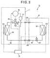
- Fig. 3 is a diagram showing a refrigerant circuit of an air conditioner.
- As shown in Fig. 3, an
air conditioner 10 includes anoutdoor unit 11, anindoor unit 12 and acontroller 13, and anoutdoor refrigerant pipe 14 of theoutdoor unit 11 and anindoor refrigerant pipe 15 of theindoor unit 12 are linked to each other throughlink pipes - The
outdoor unit 11 is disposed outdoors, and thecompressor 16 is disposed in theoutdoor refrigerant pipe 14. Anaccumulator 17 is connected to the suction side of thecompressor 16 through theoutdoor refrigerant pipe 14, a four-way change-overvalve 18 is connected to the discharge side of thecompressor 16 through theoutdoor refrigerant pipe 14, and an outdoor heat-exchanger 19 is connected to the four-way change-overvalve 18 through theoutdoor refrigerant pipe 14. Anoutdoor fan 20 for blowing air to the outdoor heat-exchanger 19 is disposed in the vicinity of the outdoor heat-exchanger 19. - Further, the
indoor unit 12 is disposed indoors, an indoor heat-exchanger 21 is disposed in theindoor refrigerant pipe 15, and anelectric expansion valve 22 is disposed in the neighborhood of the indoor heat-exchanger 21 in theindoor refrigerant pipe 15. Anindoor fan 23 for blowing air to the indoor heat-exchanger 21 is disposed in the neighborhood of the indoor heat-exchanger 21. - The
controller 13 controls the operation of theoutdoor unit 11 and theindoor unit 12, and more specifically, thecontroller 13 controls thecompressor 16, the four-way change-overvalve 18 and theoutdoor fan 20 of theoutdoor unit 11, and theelectric expansion valve 22 and theindoor fan 23 of theindoor unit 12. - The
controller 13 controls the switching operation of the four-way change-overvalve 18 to set the operation of theair conditioner 10 to one of cooling operation and heating operation. That is, when thecontroller 13 switches the four-way change-overvalve 18 to the cooling operation side, refrigerant flows as indicated by solid-line arrows. In this case, the outdoor heat-exchanger 19 serves as a condenser while the indoor heat-exchanger 21 serves as an evaporator, whereby the operation state of the air conditioner is set to the cooling operation state, and the indoor heat-exchanger 21 of theindoor unit 12 cools the room. On the other hand, when thecontroller 13 switches the four-way change-overvalve 18 to the heating operation side, the refrigerant flows as indicated by broken-line arrows. In this case, the indoor heat-exchanger 21 serves as a condenser while the outdoor heat-exchanger 19 serves as an evaporator, whereby the operation state of the air conditioner is set to the heating operation state, and the indoor heat-exchanger 21 of theindoor unit 12 heats the room. - In accordance with the air conditioning load of the
indoor unit 12, thecontroller 13 also controls the opening degree of theelectric expansion valve 22 of theindoor unit 12, and controls the fan driving system of theindoor fan 23 in theindoor unit 12. - The operation control of the
compressor 16 by thecontroller 13 is performed by using acompressor control system 30 shown in Fig. 4, and thecompressor control system 30 is constructed by not only thecontroller 13, but also apower source unit 31, apower converting device 32 and apower monitoring device 33. - Here, the
compressor 16 provides a circulating force to the refrigerant which alternately repeats condensation and compression in a refrigerant circuit, and exposes the refrigerant to a high-temperature and high-pressure process. In this embodiment, a rotary type compressor is used as thecompressor 16. As described above, the rotary type compressor and the scroll type compressor suffer a repulsive force acting in the opposite direction (reverse direction) to the normal direction from the compressed refrigerant as described above. - As in the case of the prior art, a single-phase induction motor is used as an electric motor for the
compressor 16. Although the single-phase induction motor generates more unstable rotational magnetic field as compared with a three-phase induction motor and the rotational force is inhomogeneous, it has advantages that it has a simple construction and it is designed at a low cost. - The
power source unit 31 is used to supply operating power to theair conditioner 10. It directly supplies power to thecompressor 16, theoutdoor fan 20, the four-way change-overvalve 18 and theindoor fan 23, and also supplies converted power through thepower converting device 32 to thecontroller 13 and theelectric expansion valve 22. The voltage supplied from thepower source unit 31 is set to 200V±10% in Japan, however, this voltage is not limited to the above range in the case of an independent electric power plant or overseas. - The
power converting device 32 converts the alternating power of thepower source unit 31 to DC power, stabilizes the voltage thus converted, and then supplies the DC power thus converted to parts driven by the DC power such as thecontroller 13, theelectric expansion valve 22, etc. Thepower converting device 32 is constructed by atransformer 34, a rectifying/smoothening circuit 35 and a voltage regulating (constant-voltage)circuit 36, however, a switching power source having the same function as these parts may be used. - The
transformer 34 transforms alternating power (voltage) of about 200V of thepower source unit 31 to low voltage power of about 24V. The rectifying/smoothening circuit 35 conducts full wave rectification on the low voltage alternating power from thetransformer 34 through a bridge diode or the like, and then smoothens the rectified power through an electrolytic capacitor to obtain DC power of 12V. Thereafter, thevoltage regulating circuit 36 stabilizes the DC power from the rectifying/smoothening circuit 35 through a power regulator or the like, and then sets it to low voltage DC power of about 5V. - As shown in Fig. 3, the
controller 13 controls thecompressor 16, the four-way change-overvalve 18, theoutdoor fan 20, theelectric expansion valve 22 and theindoor fan 23 to control theoverall air conditioner 10 as described above. Particularly for thecompressor 16, an operating signal α shown in Fig. 4 is output to a relay (not shown) or the like, and thecompressor 16 is started or stopped by actuating the relay or the like, thereby controlling the operation (start, stop) of thecompressor 16. - The
controller 13 includes a microcomputer, and it is necessary to reset the microcomputer of thecontroller 13 for a predetermined time after the power source is turned on because the microcomputer is often unstable at the time of power-on. The reset of the microcomputer of thecontroller 13 is carried out by inputting a reset signal β (high-level voltage or low-level voltage) to a reset port (not shown). When thecontroller 13 is reset as described above, the operating signal α to thecompressor 16 is extinguished and thecompressor 16 is stopped. The other parts such as the four-way change-overvalve 18, theoutdoor fan 20, theelectric expansion valve 22 and theindoor fan 23 are stopped in the same manner as described above. - The
power monitoring device 33 monitors the power state of thepower source unit 31, and outputs the reset signal β to thecontroller 13 at the interception time of the power of the power source unit 31 (that is, at the time of occurrence of power failure), and it comprises apulse generating circuit 37 and apulse monitoring circuit 38. - The
pulse generating circuit 37 generates pulses which are synchronized with the frequency of the power (voltage) of thepower source unit 31, and for example pulses whose period is equal to a half of the frequency of the power (voltage) of thepower source unit 31 are generated by using a photocoupler, for example. At the time of the power failure, the power supply of thepower source unit 31 is intercepted, and the supply of the pulse signals from thepulse generating circuit 37 is also stopped. - The
pulse monitoring circuit 38 monitors the pulses generated from thepulse generating circuit 37 to monitor the power state of thepower source unit 31. Thepulse monitoring circuit 38 contains a timer for counting a fixed time, and outputs the reset signal β to thecontroller 13 after the fixed time elapses from the time when no pulse is generated from thepulse generating circuit 37 due to the power failure (for example, after several tens (about 40) msec elapse from the occurrence of the power failure). - The fixed time counted after the occurrence of the power failure is set to such a time that when the power failure occurs in the refrigerant compressing process of the compressor, the compressed refrigerant applies its repulsive force acting in the opposition (reverse) direction to the roller (see
reference numeral 8A of Fig. 2) which rotates in the forward direction by the action of the inertial force, however, the roller of thecompressor 16 does not start to rotate in the reverse direction by even the repulsive force because the inertial force exceeds the repulsive force at this time. After the fixed time elapses, the roller of thecompressor 16 starts to rotate in the reverse direction with the repulsive force. - The
pulse monitoring circuit 38 continues to output the reset signal β to thecontroller 13 until a predetermined time elapses from the time when the power of thepower source unit 31 is restored and thepower source unit 31 starts to generate pulses, and stops the output of the reset signal β to actuate thecontroller 13 at the stage that the inside of the computer of thecontroller 13 is stabilized (after the predetermined time elapses). - Next, the control of the operation of the
compressor control system 30 at the power-failure time will be described in each of the following three cases: a long-term power-failure case (power failure for several hundreds msec or more), a short-term power-failure case (power failure for several tens (about 40) msec to several hundred msec) and an extremely-short-term power-failure case (power failure for several tens (about 40) msec or less). - The power supply from the
power source unit 31 to thecompressor 16 is intercepted simultaneously with occurrence of a power failure, and when the power failure occurs during the refrigerant-compressing process, the compressor suffers the repulsive force of the compressed refrigerant in the opposite direction to the forward rotational direction and thus it rotates in the reverse direction. During the long-term power failure, thepulse monitoring circuit 38 of thepower monitoring device 33 outputs the reset signal β to thecontroller 13 after the fixed time elapses (several tens (about 40) msec elapses) from the occurrence of the power failure, and thecontroller 13 is reset. The resetting of thecontroller 13 extinguishes the operating signal α output from thecontroller 13 to thecompressor 16. Accordingly, no operating signal α is output from thecontroller 13 to thecompressor 16, so that thecompressor 16 does not continue to rotate in the reverse direction and finally stops. - During the long-term power failure, the power supplied from the
voltage regulating circuit 36 of thepower converting device 32 to thecontroller 13 is intercepted after several hundreds msec elapse from the occurrence of the power failure. - As in the case of the above long-term power failure, the power to be supplied from the
power source unit 31 to thecompressor 16 is intercepted simultaneously with the occurrence of the power failure occurs. When the power failure occurs in the refrigerant-compressing process of the compressor, the compressor suffers the repulsive force of the compressed refrigerant in the reverse direction to the normal rotational direction, and starts to rotate in the reverse direction. Further, during the short-term power failure, the power supply from thevoltage regulating circuit 36 of thepower converting device 32 to thecontroller 13 is continued. However, thepulse monitoring circuit 38 of thepower monitoring device 33 outputs the reset signal β to thecontroller 13 after a fixed time (several tens (about 40) msec) elapses from the occurrence of the power failure, and resets thecontroller 13, whereby the operating signal a output from thecontroller 13 to thecompressor 16 is extinguished. Accordingly, in this case, the reverse rotation of thecompressor 16 is also stopped without being continued. - In this case, the power supply from the
power source unit 31 to thecompressor 16 is intercepted at the same time when the power failure occurs. When the power failure occurs in the refrigerant-compressing process, the compressor suffers the repulsive force of the compressed refrigerant in the reverse direction to the normal rotational direction, however, it is still under the state before it starts to rotate and rotates in the normal direction by the inertial force. During this extremely-short-term power failure, the power is supplied from thevoltage regulating circuit 36 of thepower converting device 32 to thecontroller 13, and also no reset signal is output from thepulse monitoring circuit 38 of thepower monitoring device 33 to thecontroller 13, so that thecontroller 13 is under operation. Accordingly, when the power from thepower source unit 31 is restored from the above state, the rotational force of thecompressor 16 in the same normal direction as before the power failure is increased, and theair conditioner 10 continues the operation before the power failure (cooling operation or heating operation). - With the above construction, the
compressor control system 30 of theair conditioner 10 has the following effects (1) to (3). - (1) The
power monitoring device 33 outputs the reset signal β to thecontroller 13 in the long-term or short-term power failure of thepower source unit 31, and thecontroller 13 is reset by the reset signal β to stop thecompressor 16. Therefore, in the case where the electric motor of thecompressor 16 is a single-phase induction motor, thecontroller 13 to which the power is continued to be supplied from thevoltage regulating circuit 36 of the power converting device 32 (in the case of the short-term power failure) is forcedly reset to stop thecompressor 16 even when thecompressor 16 is in the refrigerant-compressing process at the time of the occurrence of the long-term or short-term power failure and thus thecompressor 16 is forced to be rotated in the reverse direction by the repulsive force of the compressed refrigerant. Therefore, the reverse rotation phenomenon of the compressor can be surely prevented. - (2) The
power monitoring device 33 monitors the power state of thepower source unit 31 with the pulses generated in thepulse generating circuit 37, and outputs the reset signal β to thecontroller 13 when the power is intercepted (in the case of the long-term or short-term power failure). Therefore, when the voltage of thepower source unit 31 is instantaneously reduced, no reset signal β is output to thecontroller 13. Accordingly, it is avoided that thecontroller 13 is reset and the compressor is stopped when the voltage of the power source unit is instantaneously reduced. Therefore, the misoperation of thecompressor 16 can be avoided, and the reliability of the operation of theair conditioner 10 can be ensured. - (3) The
power monitoring device 33 outputs the reset signal β to thecontroller 13 after a fixed time elapses from the interception of the power of the power source unit 31 (occurrence of a power failure), and the fixed time is set to such a time that when the power failure occurs in the refrigerant-compressing process of thecompressor 16, the compressor does not start to rotate in the reverse direction by even the repulsive force of the compressed refrigerant. Therefore, in the short-term power failure in which the power interception state is continued even when the fixed time elapses from the occurrence of the power failure, the compressor starts to rotate in the reverse direction, however, thecontroller 13 is reset and thus no operating signal α is output to thecompressor 16, so that the reverse phenomenon of thecompressor 16 can be surely prevented. -
- On the other hand, in the extremely-short-term power failure in which the power interception state is finished before the fixed time elapses from the occurrence of the power failure, no reset signal β is output from the
pulse monitoring circuit 38 of thepower monitoring device 33 to thecontroller 13, and thecompressor 16 does not start to rotate in the reverse direction during this period. Therefore, thecompressor 16 is continued to rotated in the normal direction even after the extremely-short-term power failure is finished, so that the operation performance of theair conditioner 10 can be prevented from being lowered. - The present invention is not limited to the above embodiment, and various modifications may be made without departing from the subject of the present invention.
- For example, in the above embodiment, the
pulse generating circuit 37 of thepower monitoring device 33 generates the pulses on the basis of the power of thepower source unit 31. However, the pulses may be generated on the basis of the power of thetransformer 34 of thepower converting device 32. Further, thepower monitoring device 33 may directly monitor the variation of the voltage of the power source unit without transforming the power of thepower source unit 31 or thetransformer 34 to pulses. - According to the compressor control system for the air conditioner according to the present invention, the power monitoring device monitors the power state of the power source unit, and outputs the reset signal to the controller for controlling the operation of the compressor when the power supply of the power source unit is intercepted. The controller is reset by the reset signal to stop the compressor. Therefore, even when the power failure occurs in the refrigerant-compressing process of the compressor, the reverse rotation phenomenon of the compressor can be surely prevented.
Claims (8)
- A compressor control system including a controller for controlling the operation of a compressor, a power source unit for supplying power to said compressor, a power converting device for subjecting the power from said power source unit to conversion processing and then supplying the power thus converted to said controller, said controller being reset on the basis of input of a reset signal to stop said compressor, characterized by further including:a power monitoring device for monitoring a power state of said power source unit, and outputting the reset signal to said controller when the power supply of said power source unit is intercepted.
- Th compressor control system as claimed in claim 1, wherein said power monitoring device outputs the reset signal after a predetermined fixed time elapses from the interception of the power supply of said power source unit.
- The compressor control system as claimed in claim 2, wherein the predetermined fixed time is set to such a time that when the power interception occurs in a refrigerant-compressing process of said compressor, said compressor is not reversely rotated by the repulsive force of the compressed refrigerant because the inertial force of said compressor exceeds the repulsive force of the compressed refrigerant.
- The compressor control system as claimed in claim 3, wherein the predetermined fixed time is set to several tens msec.
- The compressor control system as claimed in claim 4, wherein the predetermined fixed time is set to about 40 msec.
- The compressor control system as claimed in claim 1, wherein said power monitoring device comprises a pulse generating circuit for generating pulses which are synchronized with the frequency of the power of said power source unit, the supply of the pulses from said pulse generating circuit being stopped when the power supply of said power source unit is intercepted, and a pulse monitoring circuit for monitoring the pulses generated from said pulse generating circuit to monitor the power state of said power source unit.
- The compressor control system as claimed in claim 6, wherein said pulse monitoring circuit contains a timer for counting the predetermined fixed time, and outputs the reset signal to said controller after the fixed time elapses from the time when no pulse is generated from said pulse generating circuit, thereby stopping said compressor.
- The compressor control system as claimed in claim 1, wherein the interception of the power supply is caused by a power failure.
Applications Claiming Priority (2)
| Application Number | Priority Date | Filing Date | Title |
|---|---|---|---|
| JP3198498 | 1998-01-29 | ||
| JP03198498A JP3920440B2 (en) | 1998-01-29 | 1998-01-29 | Compressor control system for air conditioner |
Publications (3)
| Publication Number | Publication Date |
|---|---|
| EP0933604A2 true EP0933604A2 (en) | 1999-08-04 |
| EP0933604A3 EP0933604A3 (en) | 2002-01-16 |
| EP0933604B1 EP0933604B1 (en) | 2005-06-08 |
Family
ID=12346203
Family Applications (1)
| Application Number | Title | Priority Date | Filing Date |
|---|---|---|---|
| EP98124884A Expired - Lifetime EP0933604B1 (en) | 1998-01-29 | 1998-12-30 | Compressor control system for air conditioner |
Country Status (7)
| Country | Link |
|---|---|
| US (1) | US6254352B1 (en) |
| EP (1) | EP0933604B1 (en) |
| JP (1) | JP3920440B2 (en) |
| KR (1) | KR100540508B1 (en) |
| DE (1) | DE69830466T2 (en) |
| ES (1) | ES2244031T3 (en) |
| PT (1) | PT933604E (en) |
Cited By (3)
| Publication number | Priority date | Publication date | Assignee | Title |
|---|---|---|---|---|
| WO2007029646A1 (en) | 2005-09-06 | 2007-03-15 | Matsushita Electric Industrial Co., Ltd. | Controller for air conditioner |
| CN100439815C (en) * | 2005-09-12 | 2008-12-03 | 松下电器产业株式会社 | Freezing circulation device |
| CN104389775A (en) * | 2014-11-03 | 2015-03-04 | 宁波奥克斯空调有限公司 | Method for protecting air conditioner compressor in case of abnormal power failure |
Families Citing this family (8)
| Publication number | Priority date | Publication date | Assignee | Title |
|---|---|---|---|---|
| JP4107789B2 (en) * | 2000-08-10 | 2008-06-25 | 三洋電機株式会社 | Power supply reverse phase detection circuit |
| KR100975578B1 (en) * | 2003-11-07 | 2010-08-13 | 삼성전자주식회사 | Air conditioner and control method thereof |
| US7375412B1 (en) * | 2005-03-31 | 2008-05-20 | Intel Corporation | iTFC with optimized C(T) |
| TW201004125A (en) * | 2008-07-15 | 2010-01-16 | Rhine Electronic Co Ltd | Ceiling fan control circuit capable of controlling forward/backward rotation and rotation speed |
| GB2547366B (en) | 2013-03-11 | 2017-11-08 | Trane Int Inc | Controls and operation of variable frequency drives |
| JP5768863B2 (en) * | 2013-11-18 | 2015-08-26 | 株式会社豊田自動織機 | Electric compressor |
| EP3916989A4 (en) * | 2019-01-24 | 2022-09-07 | Hitachi Industrial Equipment Systems Co., Ltd. | Power conversion system |
| EP3978817B1 (en) * | 2019-05-28 | 2024-01-10 | Daikin Industries, Ltd. | Air-conditioning system |
Citations (10)
| Publication number | Priority date | Publication date | Assignee | Title |
|---|---|---|---|---|
| US3535591A (en) * | 1968-01-02 | 1970-10-20 | Sola Basic Ind Inc | Monitoring system for polyphase electric supply system |
| US3946574A (en) * | 1975-02-07 | 1976-03-30 | Chrysler Corporation | Control circuit for refrigeration compressor motor |
| GB1452772A (en) * | 1973-09-20 | 1976-10-13 | Owens Illinois Inc | Apparauts for controlling centrifugal compressors |
| JPS5563343A (en) * | 1978-10-31 | 1980-05-13 | Matsushita Electric Ind Co Ltd | Controlling device for air conditioner |
| US4410991A (en) * | 1981-06-03 | 1983-10-18 | Gte Laboratories Incorporated | Supervisory control apparatus |
| US4433390A (en) * | 1981-07-30 | 1984-02-21 | The Bendix Corporation | Power processing reset system for a microprocessor responding to sudden deregulation of a voltage |
| JPS59103986A (en) * | 1982-12-03 | 1984-06-15 | Matsushita Seiko Co Ltd | Air conditioner |
| US4819237A (en) * | 1987-08-05 | 1989-04-04 | Digital Appliance Controls, Inc. | Method and apparatus for monitoring the validity of microprocess or volatile memory |
| EP0498645A2 (en) * | 1991-02-06 | 1992-08-12 | Sanyo Electric Co., Ltd | A control apparatus for an air conditioner |
| US5455469A (en) * | 1993-10-12 | 1995-10-03 | Watsco Components, Inc. | Comparator controlled delay-on-break devices |
Family Cites Families (7)
| Publication number | Priority date | Publication date | Assignee | Title |
|---|---|---|---|---|
| KR900004922Y1 (en) * | 1987-12-02 | 1990-05-31 | 삼성전자 주식회사 | Control circuit for air conditioner |
| US5006045A (en) * | 1987-12-24 | 1991-04-09 | Seiko Epson Corporation | Scroll compressor with reverse rotation speed limiter |
| US5542042A (en) * | 1993-05-27 | 1996-07-30 | Whirlpool Corporation | Method and apparatus for monitoring volatile memory validity |
| JP3258463B2 (en) * | 1993-08-30 | 2002-02-18 | 三菱重工業株式会社 | Refrigeration cycle device |
| DE4429206C2 (en) * | 1994-08-18 | 1998-04-09 | Atlas Copco Tools Ab | Device to lock or release an electric hand tool |
| JPH09121590A (en) * | 1995-09-14 | 1997-05-06 | Copeland Corp | Rotary compressor provided with counter-current braking mechanism |
| JPH09163791A (en) * | 1995-12-07 | 1997-06-20 | Sanden Corp | Driving method for motor-driven compressor and drive device |
-
1998
- 1998-01-29 JP JP03198498A patent/JP3920440B2/en not_active Expired - Fee Related
- 1998-12-11 KR KR1019980054421A patent/KR100540508B1/en not_active IP Right Cessation
- 1998-12-30 US US09/223,614 patent/US6254352B1/en not_active Expired - Lifetime
- 1998-12-30 ES ES98124884T patent/ES2244031T3/en not_active Expired - Lifetime
- 1998-12-30 EP EP98124884A patent/EP0933604B1/en not_active Expired - Lifetime
- 1998-12-30 PT PT98124884T patent/PT933604E/en unknown
- 1998-12-30 DE DE69830466T patent/DE69830466T2/en not_active Expired - Fee Related
Patent Citations (10)
| Publication number | Priority date | Publication date | Assignee | Title |
|---|---|---|---|---|
| US3535591A (en) * | 1968-01-02 | 1970-10-20 | Sola Basic Ind Inc | Monitoring system for polyphase electric supply system |
| GB1452772A (en) * | 1973-09-20 | 1976-10-13 | Owens Illinois Inc | Apparauts for controlling centrifugal compressors |
| US3946574A (en) * | 1975-02-07 | 1976-03-30 | Chrysler Corporation | Control circuit for refrigeration compressor motor |
| JPS5563343A (en) * | 1978-10-31 | 1980-05-13 | Matsushita Electric Ind Co Ltd | Controlling device for air conditioner |
| US4410991A (en) * | 1981-06-03 | 1983-10-18 | Gte Laboratories Incorporated | Supervisory control apparatus |
| US4433390A (en) * | 1981-07-30 | 1984-02-21 | The Bendix Corporation | Power processing reset system for a microprocessor responding to sudden deregulation of a voltage |
| JPS59103986A (en) * | 1982-12-03 | 1984-06-15 | Matsushita Seiko Co Ltd | Air conditioner |
| US4819237A (en) * | 1987-08-05 | 1989-04-04 | Digital Appliance Controls, Inc. | Method and apparatus for monitoring the validity of microprocess or volatile memory |
| EP0498645A2 (en) * | 1991-02-06 | 1992-08-12 | Sanyo Electric Co., Ltd | A control apparatus for an air conditioner |
| US5455469A (en) * | 1993-10-12 | 1995-10-03 | Watsco Components, Inc. | Comparator controlled delay-on-break devices |
Non-Patent Citations (2)
| Title |
|---|
| PATENT ABSTRACTS OF JAPAN vol. 004, no. 105 (M-023), 26 July 1980 (1980-07-26) & JP 55 063343 A (MATSUSHITA ELECTRIC IND CO LTD), 13 May 1980 (1980-05-13) * |
| PATENT ABSTRACTS OF JAPAN vol. 008, no. 220 (M-330), 6 October 1984 (1984-10-06) & JP 59 103986 A (MATSUSHITA SEIKO KK), 15 June 1984 (1984-06-15) * |
Cited By (3)
| Publication number | Priority date | Publication date | Assignee | Title |
|---|---|---|---|---|
| WO2007029646A1 (en) | 2005-09-06 | 2007-03-15 | Matsushita Electric Industrial Co., Ltd. | Controller for air conditioner |
| CN100439815C (en) * | 2005-09-12 | 2008-12-03 | 松下电器产业株式会社 | Freezing circulation device |
| CN104389775A (en) * | 2014-11-03 | 2015-03-04 | 宁波奥克斯空调有限公司 | Method for protecting air conditioner compressor in case of abnormal power failure |
Also Published As
| Publication number | Publication date |
|---|---|
| DE69830466T2 (en) | 2006-03-16 |
| PT933604E (en) | 2005-08-31 |
| US6254352B1 (en) | 2001-07-03 |
| EP0933604A3 (en) | 2002-01-16 |
| KR100540508B1 (en) | 2006-03-22 |
| KR19990071435A (en) | 1999-09-27 |
| EP0933604B1 (en) | 2005-06-08 |
| DE69830466D1 (en) | 2005-07-14 |
| JPH11210638A (en) | 1999-08-03 |
| ES2244031T3 (en) | 2005-12-01 |
| JP3920440B2 (en) | 2007-05-30 |
Similar Documents
| Publication | Publication Date | Title |
|---|---|---|
| US5670858A (en) | Single-phase induction motor safety controller | |
| JP2555464B2 (en) | Refrigeration cycle equipment | |
| US6065298A (en) | Air conditioner automatically controlling operation based on supply voltage or supply frequency | |
| US6962058B2 (en) | Air conditioner and method of controlling such | |
| US6254352B1 (en) | Compressor control system for air conditioner | |
| EP1536186B1 (en) | Air conditioner | |
| EP1524480B1 (en) | Method for controlling air conditioner | |
| US20040003610A1 (en) | Air conditioning system with two compressors and method for operating the same | |
| JP2000121135A (en) | Controller for air conditioner | |
| EP1936293B1 (en) | Controller for air conditioner | |
| KR102000255B1 (en) | Circuit for maintaining power | |
| JP2007024389A (en) | Controller for air conditioner | |
| JP3101380B2 (en) | Air conditioner power supply | |
| US11588427B2 (en) | Motor drive device and air conditioner | |
| JP2518114B2 (en) | Compressor drive | |
| EP3757472B1 (en) | Air-conditioner | |
| JP2581622B2 (en) | Method and apparatus for controlling capacity of screw compressor | |
| EP3276283B1 (en) | Refrigeration cycle apparatus | |
| JP4404420B2 (en) | Air conditioner control device | |
| JPH10153179A (en) | Device for protecting compressor from abnormality, and refrigerating cycle device | |
| KR101990143B1 (en) | Compressor controlling apparatus | |
| KR101957968B1 (en) | Power converting apparatus | |
| KR101979453B1 (en) | Air conditioner and controlling method for the same | |
| JPH0317165Y2 (en) | ||
| KR20190040734A (en) | Protection circuit of switchs and operating method thereof |
Legal Events
| Date | Code | Title | Description |
|---|---|---|---|
| PUAI | Public reference made under article 153(3) epc to a published international application that has entered the european phase |
Free format text: ORIGINAL CODE: 0009012 |
|
| AK | Designated contracting states |
Kind code of ref document: A2 Designated state(s): AT BE CH CY DE DK ES FI FR GB GR IE IT LI LU MC NL PT SE Kind code of ref document: A2 Designated state(s): DE ES FR GB IT PT |
|
| AX | Request for extension of the european patent |
Free format text: AL;LT;LV;MK;RO;SI |
|
| PUAL | Search report despatched |
Free format text: ORIGINAL CODE: 0009013 |
|
| AK | Designated contracting states |
Kind code of ref document: A3 Designated state(s): AT BE CH CY DE DK ES FI FR GB GR IE IT LI LU MC NL PT SE |
|
| AX | Request for extension of the european patent |
Free format text: AL;LT;LV;MK;RO;SI |
|
| RIC1 | Information provided on ipc code assigned before grant |
Free format text: 7F 25B 49/02 A, 7H 02P 6/00 B, 7F 04C 29/10 B, 7F 04B 49/10 B, 7F 16P 7/02 B, 7H 02H 7/09 B, 7H 02H 7/08 B, 7H 02H 11/00 B, 7H 02H 3/06 B |
|
| 17P | Request for examination filed |
Effective date: 20020228 |
|
| AKX | Designation fees paid |
Free format text: DE ES FR GB IT PT |
|
| 17Q | First examination report despatched |
Effective date: 20030929 |
|
| GRAP | Despatch of communication of intention to grant a patent |
Free format text: ORIGINAL CODE: EPIDOSNIGR1 |
|
| GRAS | Grant fee paid |
Free format text: ORIGINAL CODE: EPIDOSNIGR3 |
|
| GRAA | (expected) grant |
Free format text: ORIGINAL CODE: 0009210 |
|
| AK | Designated contracting states |
Kind code of ref document: B1 Designated state(s): DE ES FR GB IT PT |
|
| REG | Reference to a national code |
Ref country code: GB Ref legal event code: FG4D |
|
| REF | Corresponds to: |
Ref document number: 69830466 Country of ref document: DE Date of ref document: 20050714 Kind code of ref document: P |
|
| REG | Reference to a national code |
Ref country code: PT Ref legal event code: SC4A Effective date: 20050629 |
|
| REG | Reference to a national code |
Ref country code: ES Ref legal event code: FG2A Ref document number: 2244031 Country of ref document: ES Kind code of ref document: T3 |
|
| ET | Fr: translation filed | ||
| PLBE | No opposition filed within time limit |
Free format text: ORIGINAL CODE: 0009261 |
|
| STAA | Information on the status of an ep patent application or granted ep patent |
Free format text: STATUS: NO OPPOSITION FILED WITHIN TIME LIMIT |
|
| 26N | No opposition filed |
Effective date: 20060309 |
|
| PGFP | Annual fee paid to national office [announced via postgrant information from national office to epo] |
Ref country code: ES Payment date: 20071226 Year of fee payment: 10 |
|
| PGFP | Annual fee paid to national office [announced via postgrant information from national office to epo] |
Ref country code: GB Payment date: 20071227 Year of fee payment: 10 Ref country code: FR Payment date: 20071210 Year of fee payment: 10 |
|
| PGFP | Annual fee paid to national office [announced via postgrant information from national office to epo] |
Ref country code: PT Payment date: 20071210 Year of fee payment: 10 Ref country code: IT Payment date: 20071228 Year of fee payment: 10 Ref country code: DE Payment date: 20071231 Year of fee payment: 10 |
|
| REG | Reference to a national code |
Ref country code: PT Ref legal event code: MM4A Free format text: LAPSE DUE TO NON-PAYMENT OF FEES Effective date: 20090630 |
|
| GBPC | Gb: european patent ceased through non-payment of renewal fee |
Effective date: 20081230 |
|
| PG25 | Lapsed in a contracting state [announced via postgrant information from national office to epo] |
Ref country code: PT Free format text: LAPSE BECAUSE OF NON-PAYMENT OF DUE FEES Effective date: 20090630 |
|
| REG | Reference to a national code |
Ref country code: FR Ref legal event code: ST Effective date: 20090831 |
|
| PG25 | Lapsed in a contracting state [announced via postgrant information from national office to epo] |
Ref country code: DE Free format text: LAPSE BECAUSE OF NON-PAYMENT OF DUE FEES Effective date: 20090701 |
|
| PG25 | Lapsed in a contracting state [announced via postgrant information from national office to epo] |
Ref country code: GB Free format text: LAPSE BECAUSE OF NON-PAYMENT OF DUE FEES Effective date: 20081230 |
|
| REG | Reference to a national code |
Ref country code: ES Ref legal event code: FD2A Effective date: 20081231 |
|
| PG25 | Lapsed in a contracting state [announced via postgrant information from national office to epo] |
Ref country code: FR Free format text: LAPSE BECAUSE OF NON-PAYMENT OF DUE FEES Effective date: 20081231 Ref country code: ES Free format text: LAPSE BECAUSE OF NON-PAYMENT OF DUE FEES Effective date: 20081231 |
|
| PG25 | Lapsed in a contracting state [announced via postgrant information from national office to epo] |
Ref country code: IT Free format text: LAPSE BECAUSE OF NON-PAYMENT OF DUE FEES Effective date: 20081230 |