EP0933558B1 - Stepped automotive gearbox - Google Patents
Stepped automotive gearbox Download PDFInfo
- Publication number
- EP0933558B1 EP0933558B1 EP99101287A EP99101287A EP0933558B1 EP 0933558 B1 EP0933558 B1 EP 0933558B1 EP 99101287 A EP99101287 A EP 99101287A EP 99101287 A EP99101287 A EP 99101287A EP 0933558 B1 EP0933558 B1 EP 0933558B1
- Authority
- EP
- European Patent Office
- Prior art keywords
- transmission
- gear
- shaft
- clutch
- output shaft
- Prior art date
- Legal status (The legal status is an assumption and is not a legal conclusion. Google has not performed a legal analysis and makes no representation as to the accuracy of the status listed.)
- Expired - Lifetime
Links
Images

Classifications
-
- F—MECHANICAL ENGINEERING; LIGHTING; HEATING; WEAPONS; BLASTING
- F16—ENGINEERING ELEMENTS AND UNITS; GENERAL MEASURES FOR PRODUCING AND MAINTAINING EFFECTIVE FUNCTIONING OF MACHINES OR INSTALLATIONS; THERMAL INSULATION IN GENERAL
- F16H—GEARING
- F16H3/00—Toothed gearings for conveying rotary motion with variable gear ratio or for reversing rotary motion
- F16H3/02—Toothed gearings for conveying rotary motion with variable gear ratio or for reversing rotary motion without gears having orbital motion
- F16H3/08—Toothed gearings for conveying rotary motion with variable gear ratio or for reversing rotary motion without gears having orbital motion exclusively or essentially with continuously meshing gears, that can be disengaged from their shafts
- F16H3/087—Toothed gearings for conveying rotary motion with variable gear ratio or for reversing rotary motion without gears having orbital motion exclusively or essentially with continuously meshing gears, that can be disengaged from their shafts characterised by the disposition of the gears
- F16H3/093—Toothed gearings for conveying rotary motion with variable gear ratio or for reversing rotary motion without gears having orbital motion exclusively or essentially with continuously meshing gears, that can be disengaged from their shafts characterised by the disposition of the gears with two or more countershafts
- F16H3/097—Toothed gearings for conveying rotary motion with variable gear ratio or for reversing rotary motion without gears having orbital motion exclusively or essentially with continuously meshing gears, that can be disengaged from their shafts characterised by the disposition of the gears with two or more countershafts the input and output shafts being aligned on the same axis
-
- F—MECHANICAL ENGINEERING; LIGHTING; HEATING; WEAPONS; BLASTING
- F16—ENGINEERING ELEMENTS AND UNITS; GENERAL MEASURES FOR PRODUCING AND MAINTAINING EFFECTIVE FUNCTIONING OF MACHINES OR INSTALLATIONS; THERMAL INSULATION IN GENERAL
- F16H—GEARING
- F16H3/00—Toothed gearings for conveying rotary motion with variable gear ratio or for reversing rotary motion
- F16H3/006—Toothed gearings for conveying rotary motion with variable gear ratio or for reversing rotary motion power being selectively transmitted by either one of the parallel flow paths
-
- F—MECHANICAL ENGINEERING; LIGHTING; HEATING; WEAPONS; BLASTING
- F16—ENGINEERING ELEMENTS AND UNITS; GENERAL MEASURES FOR PRODUCING AND MAINTAINING EFFECTIVE FUNCTIONING OF MACHINES OR INSTALLATIONS; THERMAL INSULATION IN GENERAL
- F16H—GEARING
- F16H3/00—Toothed gearings for conveying rotary motion with variable gear ratio or for reversing rotary motion
- F16H3/02—Toothed gearings for conveying rotary motion with variable gear ratio or for reversing rotary motion without gears having orbital motion
- F16H3/08—Toothed gearings for conveying rotary motion with variable gear ratio or for reversing rotary motion without gears having orbital motion exclusively or essentially with continuously meshing gears, that can be disengaged from their shafts
- F16H2003/0815—Toothed gearings for conveying rotary motion with variable gear ratio or for reversing rotary motion without gears having orbital motion exclusively or essentially with continuously meshing gears, that can be disengaged from their shafts using torque sharing, i.e. engaging two gear ratios simultaneously to transfer large torque, e.g. using one slipping clutch
-
- F—MECHANICAL ENGINEERING; LIGHTING; HEATING; WEAPONS; BLASTING
- F16—ENGINEERING ELEMENTS AND UNITS; GENERAL MEASURES FOR PRODUCING AND MAINTAINING EFFECTIVE FUNCTIONING OF MACHINES OR INSTALLATIONS; THERMAL INSULATION IN GENERAL
- F16H—GEARING
- F16H61/00—Control functions within control units of change-speed- or reversing-gearings for conveying rotary motion ; Control of exclusively fluid gearing, friction gearing, gearings with endless flexible members or other particular types of gearing
- F16H61/04—Smoothing ratio shift
- F16H61/0403—Synchronisation before shifting
- F16H2061/0407—Synchronisation before shifting by control of clutch in parallel torque path
-
- F—MECHANICAL ENGINEERING; LIGHTING; HEATING; WEAPONS; BLASTING
- F16—ENGINEERING ELEMENTS AND UNITS; GENERAL MEASURES FOR PRODUCING AND MAINTAINING EFFECTIVE FUNCTIONING OF MACHINES OR INSTALLATIONS; THERMAL INSULATION IN GENERAL
- F16H—GEARING
- F16H61/00—Control functions within control units of change-speed- or reversing-gearings for conveying rotary motion ; Control of exclusively fluid gearing, friction gearing, gearings with endless flexible members or other particular types of gearing
- F16H61/04—Smoothing ratio shift
- F16H2061/0425—Bridging torque interruption
- F16H2061/0429—Bridging torque interruption by torque supply with a clutch in parallel torque path
-
- F—MECHANICAL ENGINEERING; LIGHTING; HEATING; WEAPONS; BLASTING
- F16—ENGINEERING ELEMENTS AND UNITS; GENERAL MEASURES FOR PRODUCING AND MAINTAINING EFFECTIVE FUNCTIONING OF MACHINES OR INSTALLATIONS; THERMAL INSULATION IN GENERAL
- F16H—GEARING
- F16H2200/00—Transmissions for multiple ratios
- F16H2200/003—Transmissions for multiple ratios characterised by the number of forward speeds
- F16H2200/0052—Transmissions for multiple ratios characterised by the number of forward speeds the gear ratios comprising six forward speeds
-
- F—MECHANICAL ENGINEERING; LIGHTING; HEATING; WEAPONS; BLASTING
- F16—ENGINEERING ELEMENTS AND UNITS; GENERAL MEASURES FOR PRODUCING AND MAINTAINING EFFECTIVE FUNCTIONING OF MACHINES OR INSTALLATIONS; THERMAL INSULATION IN GENERAL
- F16H—GEARING
- F16H2306/00—Shifting
-
- F—MECHANICAL ENGINEERING; LIGHTING; HEATING; WEAPONS; BLASTING
- F16—ENGINEERING ELEMENTS AND UNITS; GENERAL MEASURES FOR PRODUCING AND MAINTAINING EFFECTIVE FUNCTIONING OF MACHINES OR INSTALLATIONS; THERMAL INSULATION IN GENERAL
- F16H—GEARING
- F16H61/00—Control functions within control units of change-speed- or reversing-gearings for conveying rotary motion ; Control of exclusively fluid gearing, friction gearing, gearings with endless flexible members or other particular types of gearing
- F16H61/68—Control functions within control units of change-speed- or reversing-gearings for conveying rotary motion ; Control of exclusively fluid gearing, friction gearing, gearings with endless flexible members or other particular types of gearing specially adapted for stepped gearings
- F16H61/684—Control functions within control units of change-speed- or reversing-gearings for conveying rotary motion ; Control of exclusively fluid gearing, friction gearing, gearings with endless flexible members or other particular types of gearing specially adapted for stepped gearings without interruption of drive
- F16H61/688—Control functions within control units of change-speed- or reversing-gearings for conveying rotary motion ; Control of exclusively fluid gearing, friction gearing, gearings with endless flexible members or other particular types of gearing specially adapted for stepped gearings without interruption of drive with two inputs, e.g. selection of one of two torque-flow paths by clutches
-
- Y—GENERAL TAGGING OF NEW TECHNOLOGICAL DEVELOPMENTS; GENERAL TAGGING OF CROSS-SECTIONAL TECHNOLOGIES SPANNING OVER SEVERAL SECTIONS OF THE IPC; TECHNICAL SUBJECTS COVERED BY FORMER USPC CROSS-REFERENCE ART COLLECTIONS [XRACs] AND DIGESTS
- Y10—TECHNICAL SUBJECTS COVERED BY FORMER USPC
- Y10T—TECHNICAL SUBJECTS COVERED BY FORMER US CLASSIFICATION
- Y10T74/00—Machine element or mechanism
- Y10T74/19—Gearing
- Y10T74/19219—Interchangeably locked
- Y10T74/19233—Plurality of counter shafts
-
- Y—GENERAL TAGGING OF NEW TECHNOLOGICAL DEVELOPMENTS; GENERAL TAGGING OF CROSS-SECTIONAL TECHNOLOGIES SPANNING OVER SEVERAL SECTIONS OF THE IPC; TECHNICAL SUBJECTS COVERED BY FORMER USPC CROSS-REFERENCE ART COLLECTIONS [XRACs] AND DIGESTS
- Y10—TECHNICAL SUBJECTS COVERED BY FORMER USPC
- Y10T—TECHNICAL SUBJECTS COVERED BY FORMER US CLASSIFICATION
- Y10T74/00—Machine element or mechanism
- Y10T74/19—Gearing
- Y10T74/19219—Interchangeably locked
- Y10T74/19284—Meshing assisters
Description
Die Erfindung betrifft ein Kraftfahrzeug-Stufengetriebe in Vorgelegebauart mit einer von einer Motorausgangswelle über eine Trennkupplung antreibbaren Getriebeeingangswelle, mit einer in Verlängerung der Getriebeeingangswelle angeordneten Getriebeausgangswelle sowie mit einer zur Getriebeausgangswelle parallelen Vorgelegewelle, mit einer Mehrzahl von Radsätzen zum Einstellen von Gängen des Getriebes, wobei Radsätze jeweils ein Losrad umfassen und die Losräder über Schaltkupplungen zum Einlegen von Gängen mit einer sie tragenden Welle drehfest verbindbar sind, während ein Radsatz eines weiteren Ganges über eine Reibungskupplung schaltbar ist, und schließlich zum Vermindern eines Schaltrucks während eines Gangwechsels die Reibungskupplung beim Betätigen einer der Schaltkupplungen in Eingriff bringbar ist, wobei ferner ein Zahnrad des Radsatzes des weiteren Ganges auf einer zur Getriebeausgangswelle parallel angeordneten Nebenwelle angeordnet ist, wobei eine Drehmomentverbindung von der Motorausgangswelle über die Reibungskupplung zu dem Radsatz des weiteren Ganges herstellbar ist, und wobei der weitere Gang der zweite Gang ist.The invention relates to a motor vehicle step transmission in countershaft design with one from an engine output shaft via a Separating clutch drivable transmission input shaft, with an in Extension of the transmission input shaft arranged transmission output shaft and with a parallel to the transmission output shaft Layshaft, with a plurality of wheelsets for adjustment of gears of the transmission, with wheel sets one each Include idler gear and the idler gears via clutches for insertion of gears can be rotatably connected to a shaft carrying them are over another gear while a wheelset a friction clutch is switchable, and finally to reduce the friction clutch during a gear change engages when actuating one of the clutches can be brought, wherein also a gear of the wheelset another gear on a parallel to the transmission output shaft arranged auxiliary shaft is arranged, wherein a torque connection from the engine output shaft via the friction clutch to the wheel set of the further gear can be produced, and the further gear being the second gear.
Ein Stufengetriebe der vorstehend genannten Art ist aus der US 5603242 A bekannt.A step transmission of the type mentioned above is from the US 5603242 A known.
Bei Kraftfahrzeuggetrieben unterscheidet man zwischen sogenannten Lastschaltgetrieben einerseits und Getrieben mit Zugkraftunterbrechung andererseits. Lastschaltgetriebe sind üblicherweise als Planetengetriebe mit vorgeschaltetem hydrodynamischem Wandler ausgebildet. Durch Betätigen von Kupplungen und Bremsen für die einzelnen Elemente des Planetengetriebes werden die Gänge eines solches Lastschaltgetriebes in zeitlicher Überschneidung geschaltet, so daß während eines Gangwechsels keine Unterbrechung der Zugkraft vom Motor zu den Räder des Kraftfahrzeuges auftritt.A distinction is made between so-called Power shift transmissions on the one hand and transmissions with traction interruption on the other hand. Power shift transmissions are common as a planetary gear with an upstream hydrodynamic Converter trained. By actuating clutches and brakes for the individual elements of the planetary gear Gears of such a powershift transmission overlap in time switched so that during a gear change none Interruption of traction from the engine to the wheels of the motor vehicle occurs.
Bei Getriebe mit Zugkraftunterbrechung, bspw. herkömmlichen Kraftfahrzeug-Stufengetrieben in Vorgelegebauweise, wird hingegen der Kraftfluß bei jedem Gangwechsel zunächst im alten Gang aufgetrennt und dann im neuen Gang wieder geschlossen, so daß während des Gangwechsels eine Unterbrechung der Zugkraft eintritt. Diese Unterbrechung macht sich als Schaltruck bemerkbar, der insbesondere beim Hochschalten von niedrigeren in höhere Gänge störend sein kann, wenn das Fahrzeug infolge der Zugkraft-Unterbrechung "nickt". For gear units with traction interruption, e.g. conventional Motor vehicle step transmission in countershaft construction, however, is the power flow with every gear change initially in the old gear separated and then closed again in the new corridor, so that there is an interruption in the tractive force during the gear change. This interruption is noticeable as a shift jerk, especially when shifting from lower to higher Gears can be disruptive if the vehicle is disconnected due to traction "Winks".
Im Rahmen der Automatisierung von Schaltgetrieben mit Zugkraftunterbrechung hat man versucht, den Schaltruck dadurch zu vermindern, daß man zwei konzentrisch angeordnete und baulich vereinigte Reibungskupplungen eingesetzt hat, um jeweils eine erste oder eine zweite Gruppe von Gängen des Getriebes mit dem Ausgang des Antriebsmotors zu verbinden. Diese Getriebe werden üblicherweise als Doppelkupplungsgetriebe bezeichnet. Ein Beispiel eines derartigen Doppelkupplungsgetriebes ist in der DE 38 12 359 A1 beschrieben.As part of the automation of manual transmissions with traction interruption they tried to reduce the shift shock by that two concentrically arranged and structurally combined Friction clutches has been used to make a first or a second group of gears of the transmission with the To connect the output of the drive motor. These gears will be usually referred to as a double clutch transmission. An example of such a double clutch transmission is in DE 38 12 359 A1.
Bei einer Variante derartiger Doppelkupplungsgetriebe, wie sie bspw. in der DE 44 01 812 A1 beschrieben ist, aber auch in der DE 40 31 851 A1, der DE 195 48 622 C1 und der DE 31 31 139 C2, ist die Doppelkupplung zwar ebenfalls als Bauteil mit koaxialer Anordnung der beiden Kupplungen in einem gemeinsamen Kupplungsgehäuse ausgeführt, die Funktionsweise ist jedoch gegenüber dem weiter oben geschilderten Prinzip herkömmlicher Doppelkupplungsgetriebe etwas anders. Bei diesen Getrieben wird nämlich über eine. der beiden Reibungskupplungen der Doppelkupplung nur der jeweils höchste Gang, bspw. der sechste Gang (DE 44 01 812 A1) betätigt, und zwar während jedes Schaltvorganges. Dies hat zur Folge, daß während eines Schaltvorganges, bei dem in herkömmlichen Stufengetrieben mit Zugkraftunterbrechung der Kraftfluß zwischen Motor und Getriebeausgang vollständig unterbrochen wird, noch eine gewisse Drehmomentverbindung über den höchsten Gang vorhanden ist.In a variant of such double clutch transmission, as they For example, is described in DE 44 01 812 A1, but also in DE 40 31 851 A1, DE 195 48 622 C1 and DE 31 31 139 C2, is the double clutch also as a component with coaxial Arrangement of the two clutches in a common clutch housing executed, but the mode of operation is opposite to that Principle of conventional double clutch transmission described above something else. With these gears is namely over a. of the two friction clutches of the double clutch only the highest gear in each case, for example the sixth gear (DE 44 01 812 A1) actuated, namely during each switching operation. this has with the result that during a switching operation in which in conventional Stage gear with traction power interruption of the power flow completely interrupted between engine and transmission output is still a certain torque connection over the highest gear is present.
Bei dieser Bauart von Getrieben wird zwar der Schaltruck geringfügig vermindert, der auf diese Weise erzielte Gewinn an Komfort muß jedoch durch einen beträchtlichen konstruktiven Aufwand erkauft werden.With this type of gearbox, the shift shock is negligible reduced, the profit achieved in this way However, comfort must go through a considerable constructive Effort to be bought.
Darüber hinaus haben Getriebe dieser Bauart den systematischen Nachteil, daß nur das kleinste zur Verfügung stehende Moment, nämlich das Moment des höchsten Ganges auf den Abtrieb gebracht werden kann. Bei einem Hochschalten vom ersten in den zweiten Gang, wo sich die Komforteinbußen durch einen Schaltruck am meisten bemerkbar machen, wirkt sich dies nur geringfügig aus, weil der Zugkrafteinbruch im ersten Gang nur minimal reduziert wird. Erst beim Schalten in noch höhere Gänge wirkt sich die Einschaltung des höchsten Ganges während des Schaltvorganges mehr und mehr aus.In addition, gearboxes of this type have the systematic Disadvantage that only the smallest available moment, namely the moment of the highest gear brought to the downforce can be. When shifting up from the first to the second Corridor, where the loss of comfort by a shift jerk on make it noticeable to most people, because the drop in traction in first gear is only minimally reduced becomes. It only takes effect when shifting into even higher gears Switching on the highest gear during the switching process more and more out.
Weiterhin haben diese bekannten Getriebe den Nachteil, daß für die gewünschte Überbrückung des Moments die Kupplung für den höchsten Gang während des gesamten Schaltvorganges im Schlupfbetrieb arbeitet. Dies führt insbesondere bei zahlreichen Schaltvorgängen (Stadtverkehr) zu einem hohen Verschleiß und damit einer geringen Lebensdauer der Kupplung. Dies gilt insbesondere auch deswegen, weil die Differenzdrehzahl in der im Schlupfbetrieb laufenden Kupplung des höchsten Ganges bei Schaltungen in den unteren Gängen groß ist und erst bei Schaltungen in den oberen Gängen geringer wird. Da im Stadtverkehr jedoch häufig in den unteren Gängen geschaltet wird, bspw. bei jedem Anfahren an einer Kreuzung oder einer Verkehrsampel, wirkt sich dies ebenfalls nachteilig auf Verschleiß und Lebensdauer der Kupplung des höchsten Ganges aus. Furthermore, these known transmissions have the disadvantage that for the desired bridging of the torque for the clutch highest gear during the entire switching process in slip operation is working. This leads in particular to numerous Gear changes (city traffic) to a high wear and tear thus a short service life of the clutch. This is especially true also because the differential speed in the im Slipping operation clutch at the highest gear Shifting in the lower gears is large and only with shifting gets lower in the upper gears. Because in city traffic but is often shifted in the lower gears, for example every start at an intersection or traffic lights, this also adversely affects wear and durability the clutch of the highest gear.
Aus der DE 38 12 327 C2 ist ein Doppelkupplungsgetriebe bekannt,
bei dem mit der einen der beiden Kupplungen der erste
Gang und mit der anderen Kupplung der zweite Gang geschaltet
werden kann. Mit diesem bekannten Getriebe kann bei Schließen
beider Kupplungen mit gleichzeitig eingelegtem ersten und zweiten
Gang angefahren werden. Wenn die Drehzahlen an den Kupplungen
gleich groß sind, wird der Kraftfluß durch die Kupplung des
ersten Ganges aufgetrennt, z.B. mittels eines Freilaufes. Auf
diese Weise kann bei extremen Anfahrvorgängen die Verlustleistung
auf die beiden Kupplungen verteilt werden.A double clutch transmission is known from
Die WO 97/33103 betrifft ein Stufengetriebe für Nutzfahrzeuge. Eingangsseitig ist eine Naß-Doppelkupplung angeordnet, die alternierend betätigt wird und mit zwei konzentrisch angeordneten Getriebeeingangswellen gekoppelt ist. Ferner weist das Getriebe zwei Vorgelegewellen auf. Eine der Vorgelegewellen weist eine zentrale Synchronisierungseinrichtung auf, die zwei Synchronräder beinhaltet. Eines der Synchronräder ist formschlüssig mit der Vorgelegewelle verbindbar, so daß das Synchronrad als Schaltrad für einen Zusatzgang (z.B. Kriechgang oder Overdrive) dienen kann.WO 97/33103 relates to a step transmission for commercial vehicles. On the input side is a wet double clutch arranged, which is operated alternately and concentrically with two arranged transmission input shafts is coupled. Further the transmission has two countershafts. One of the countershafts has a central synchronization device on, which includes two synchronous wheels. One of the synchronous wheels is positively connected to the countershaft, so that Synchronous wheel as a shift wheel for an additional gear (e.g. creeper gear or overdrive).
Ein Getriebekonzept gemäß dem Oberbegriff des Anspruchs 1 ist bekannt aus der eingangs genannten US-A-5,603,242. Das Getriebe weist eine eingangsseitige Doppelkupplung auf, die mit zwei Getriebeeingangswellen verbunden ist. Zwei Vorgelegewellen sind konzentrisch zueinander angeordnet. Eine Schaltsteuereinrichtung weist einen Motor auf, der zwischen den konzentrischen Vorgelegewellen angeschlossen ist, um während Gangwechseln die relativen Drehzahlen der Vorgelegewellen aufrecht zu erhalten. A transmission concept according to the preamble of claim 1 is known from the initially mentioned US-A-5,603,242. The transmission has a double clutch on the input side connected to two transmission input shafts is. Two countershafts are arranged concentrically to each other. A shift control device has a motor that is connected between the concentric countershafts around the relative speeds of the countershafts during gear changes to maintain.
Wie klassischerweise bei Doppelkupplungsgetrieben üblich, sind dem einen Kraftübertragungszweig die geraden und dem anderen Kraftübertragungszweig die ungeraden Gänge zugeordnet.As is traditionally the case with dual clutch transmissions one straight transmission branch and the other Power transmission branch assigned the odd gears.
Der Erfindung liegt demgegenüber die Aufgabe zugrunde, ein Stufengetriebe der eingangs genannten Art dahingehend weiterzubilden, daß bei geringstmöglichem konstruktiven Aufwand und ohne Einbuße an Lebensdauer eine deutliche Komfortverbesserung in den für das Auftreten des Schaltrucks besonders wichtigen Gängen erreicht wird.In contrast, the invention is based on the object of a stepped transmission of the type mentioned at the outset, that with the least possible design effort and without Losses in service life a significant improvement in comfort the gears that are particularly important for the appearance of the gearshift is achieved.
Diese Aufgabe wird erfindungsgemäß dadurch gelöst, daß der weitere Gang (2.) als einziger über die Reibungskupplung (82) schaltbar ist.This object is achieved in that the further gear (2nd) is the only one via the friction clutch (82) is switchable.
Die der Erfindung zugrunde liegende Aufgabe wird auf diese Weise vollkommen gelöst.The object underlying the invention is achieved in this way completely solved.
Durch das Vorsehen eines zweiten Pfades zur Drehmomentverteilung vom Motor her ist man nämlich in der weiteren konstruktiven Auslegung frei. Dies gilt sowohl hinsichtlich der verwendeten Reibungskupplung, die nicht notwendigerweise Bestandteil einer herkömmlichen Doppelkupplung sein muß, wie auch hinsichtlich der Wahl und der Positionierung desjenigen Ganges, in den das vom Eingang her verzweigte Drehmoment eingeleitet wird. Man kann daher in vorteilhafter Weise von nahezu unveränderten Standardgetrieben ausgehen und muß diese lediglich durch einige zusätzliche Komponenten ergänzen. By providing a second path for torque distribution from the engine point of view, one is in the further constructive Interpretation free. This applies to both the used Friction clutch, which is not necessarily part a conventional double clutch must be, as well as in terms the choice and positioning of the gears in which the torque branched from the input is initiated. you can therefore be advantageous from almost unchanged Standard gearboxes go out and only have to go through a few add additional components.
Die Maßnahme, daß der weitere Gang der zweite Gang ist, vermeidet die weiter oben im einzelnen erläuterten Nachteile des Standes der Technik, weil durch das zusätzliche Einschalten des zweiten Ganges während des Schaltvorganges ein erheblicher Teil des Momentes über das Getriebe geleitet wird, so daß der Schaltruck dadurch deutlich vermindert werden kann. Darüber hinaus gestattet die Einschaltung einer Reibungskupplung in den Kraft- bzw. Momentenfluß des zweiten Ganges, die hinsichtlich eines Auftretens von Schaltruck besonders empfindlichen niedrigeren Gänge im Wege einer reinen Lastschaltung zu wechseln, bei der also überhaupt keine Zugkraftunterbrechung eintritt.The measure that the further gear is the second gear is avoided the disadvantages of the State of the art, because by switching on the additional second gear during the switching process a considerable part of the moment is passed through the transmission, so that the shift shock can be significantly reduced. Furthermore allows the engagement of a friction clutch in the power or torque flow of the second gear, which with respect to a Occurrence of shift jerk particularly sensitive lower To change gears by means of a pure power shift, in which so there is no interruption in tractive power at all.
Die Maßnahme, daß der weitere Gang als einziger über die Reibungskupplung schaltbar ist, bedeutet einen geringst-möglichen Außwand.The measure that the further course is the only one over the Friction clutch is switchable means the least possible Außwand.
Wie bereits erwähnt wurde, kann die Reibungskupplung sowohl in an sich bekannter Weise als Teil einer Doppelkupplung ausgebildet und dort mit der üblichen Trennkupplung im Getriebeeingang baulich vereinigt sein. Alternativ ist aber auch möglich, die Reibungskupplung auf der Nebenwelle anzuordnen und zum Verbinden eines als Losrad ausgebildeten und auf der Nebenwelle laufenden Zahnrades des Radsatzes des weiteren Ganges vorzusehen.As already mentioned, the friction clutch can be used both in formed in a known manner as part of a double clutch and there with the usual disconnect clutch in the transmission input be structurally united. Alternatively, it is also possible that Arrange friction clutch on the countershaft and connect one designed as an idler gear and running on the countershaft To provide gear of the gear set of the further gear.
Diese Maßnahme hat den Vorteil, daß der Getriebeeingang überhaupt nicht modifiziert zu werden braucht, weil die herkömmliche Trennkupplung im Getriebeeingang erhalten bleiben kann und lediglich für eine Momentenverbindung zwischen der Motorausgangswelle und der Nebenwelle gesorgt werden muß, z.B. über einen einfachen Radsatz. Da die Reibungskupplung in diesem Fall auf der Nebenwelle angeordnet ist, hat man hinsichtlich ihrer konstruktiven Ausgestaltung auch alle denkbaren Freiheitsgrade.This measure has the advantage that the transmission input at all need not be modified because the conventional one Separating clutch can be retained in the transmission input and only for a torque connection between the motor output shaft and the auxiliary shaft must be taken care of, e.g. about one simple wheelset. Because the friction clutch in this case is arranged on the auxiliary shaft, one has with regard to their constructive design also all conceivable degrees of freedom.
Bei einer weiteren bevorzugten Gruppe von Ausführungsbeispielen ist eines der Zahnräder des Radsatzes des weiteren Ganges als auf der Nebenwelle laufendes Losrad ausgebildet, und es ist eine Kupplung zum drehfesten Verbinden dieses Zahnrades mit der Nebenwelle vorgesehen. Die Kupplung kann dabei alternativ als eine mittels einer Schiebemuffe betätigbare Schaltkupplung oder aber auch als Reibungskupplung ausgebildet sein.In another preferred group of exemplary embodiments is one of the gears of the further gear set idler gear running on the countershaft, and it is a Coupling for non-rotatably connecting this gear with the Counter shaft provided. The clutch can alternatively as a shift clutch operable by means of a sliding sleeve or but also be designed as a friction clutch.
Diese Maßnahme hat den Vorteil, daß die Elemente des Nebenpfades für das Drehmoment, d.h. die auf der Nebenwelle laufenden Elemente, dann, wenn sie nicht für einen Schaltvorgang benötigt werden, entkoppelt sind, so daß sie nicht mit hohen Drehzahlen umlaufen. Auf diese Weise wird ein frühzeitiger Verschleiß der Reibungskupplung vermieden, weil diese nur noch während der Schaltvorgänge mitläuft und selbstverständlich dann, wenn der ihr zugeordnete Gang geschaltet ist. This measure has the advantage that the elements of the secondary path for the torque, i.e. those running on the countershaft Elements when they are not needed for a switching operation are decoupled so that they are not at high speeds circulate. In this way, premature wear of the Avoided friction clutch, because this only during the Switching processes runs and of course when the your assigned gear is engaged.
Bei weiteren Ausführungsformen der Erfindung sind alle Losräder auf der Getriebeausgangswelle angeordnet.In further embodiments of the invention, all idler gears arranged on the transmission output shaft.
Diese Maßnahme hat den Vorteil, daß einfache, herkömmliche Konstruktionen verwendet werden können.This measure has the advantage that simple, conventional designs can be used.
In diesem Falle ist bevorzugt, wenn ein Zahnrad des Radsatzes des weiteren Ganges als Festrad auf der Getriebeausgangswelle angeordnet ist. Insbesondere können die Radsätze der Gänge in diesem Fall, vom Getriebeeingang her gesehen, in der Reihenfolge 5.-6.-2.-4.-3.-1.-R angeordnet sein.In this case it is preferred if a gear of the gear set further gear as a fixed gear on the transmission output shaft is arranged. In particular, the wheelsets of the gears in in this case, from the transmission input, in the order 5th-6th-2nd-4th-3rd-1st-row must be arranged.
Diese Maßnahme hat den Vorteil, daß eine besonders zweckmäßige Anordnung der Gänge erreicht wird.This measure has the advantage that it is particularly useful Arrangement of the gears is achieved.
Alternativ kann aber auch bei anderen Ausführungsformen der Erfindung eine erste Anzahl von Losrädern auf der Getriebeausgangswelle und eine zweite Anzahl von Losrädern auf der Vorgelegewelle angeordnet sein.Alternatively, however, it can also be used in other embodiments of the invention a first number of idler gears on the transmission output shaft and a second number of idler gears on the countershaft be arranged.
Diese Maßnahme hat den Vorteil, daß möglicherweise eine noch kompaktere Bauart des Getriebes entsteht, weil die platzaufwendigen Schiebemuffenanordnungen auf die Getriebeausgangswelle und auf die Vorgelegewelle verteilt sind.This measure has the advantage that there may still be one compact design of the gearbox arises because of the space-consuming Sliding sleeve arrangements on the transmission output shaft and are distributed on the countershaft.
Die beiden vorstehend genannten Ausführungsformen von Getrieben bedingen naturgemäß eine ebenso unterschiedliche Aufteilung der Schaltstangen und Schaltgabeln nebst gegebenenfalls zugehörigen fremdkraftbetätigten Aktuatoren. The two above-mentioned embodiments of gears naturally require an equally different distribution of the Shift rods and shift forks along with any associated ones powered actuators.
Bei der zweiten Gruppe von Ausführungsbeispielen ist die Anordnung zweckmäßigerweise so gewählt, daß die Radsätze des weiteren Ganges und eines anderen Ganges ein Zahnrad gemeinsam haben. Dieses gemeinsame Zahnrad sitzt vorzugsweise auf der Getriebeausgangswelle und ist weiter vorzugsweise als Festrad ausgebildet.The arrangement is for the second group of exemplary embodiments expediently chosen so that the wheelsets further Gear and another gear have a gear in common. This common gear is preferably seated on the transmission output shaft and is further preferred as a fixed gear educated.
Diese Maßnahme hat den Vorteil, daß eine Radsatzebene eingespart wird, so daß sich die Baulänge entsprechend vermindert.This measure has the advantage that one wheel set plane is saved is, so that the overall length is reduced accordingly.
In diesem Falle ist ferner bevorzugt, wenn die Radsätze der Gänge, vom Getriebeeingang her gesehen, in der Reihenfolge 5.-6.-2./3.-4.-1.R angeordnet sind.In this case, it is also preferred if the wheelsets Gears, seen from the transmission input, in the order 5.-6.-2./3.-4.-1.R are arranged.
Schließlich ist bevorzugt, wenn in an sich bekannter Weise zum Anfahren die Kupplungen des ersten und des zweiten Ganges gleichzeitig betätigbar sind.Finally, it is preferred if in a manner known per se for Start the clutches of the first and second gear can be operated simultaneously.
Weitere Vorteile ergeben sich aus der Beschreibung und der beigefügten Zeichnung.Further advantages result from the description and the attached one Drawing.
Es versteht sich, daß die vorstehend genannten und die nachstehend noch zu erläuternden Merkmale nicht nur in der jeweils angegebenen Kombination, sondern auch in anderen Kombinationen oder in Alleinstellung verwendbar sind, ohne den Rahmen der vorliegenden Erfindung zu verlassen.It is understood that the above and those below Features still to be explained not only in the specified Combination, but also in other combinations or can be used alone without the scope of the to leave the present invention.
Ausführungsbeispiele der Erfindung sind in der Zeichnung dargestellt und werden in der nachfolgenden Beschreibung näher erläutert. Es zeigen:
- Fig. 1
- ein Getriebeschema eines ersten Ausführungsbeispiels eines erfindungsgemäßen Kraftfahrzeug-Stufengetriebes;
- Fig. 2
- eine Darstellung ähnlich Fig. 1, jedoch für ein zweites Ausführungsbeispiel der Erfindung;
- Fig. 3
- eine Darstellung ähnlich Fig. 1, jedoch für ein drittes Ausführungsbeispiel der Erfindung; und
- Fig. 4
- eine Darstellung ähnlich Fig. 1, jedoch für ein viertes Ausführungsbeispiel der Erfindung.
- Fig. 1
- a transmission diagram of a first embodiment of a motor vehicle multi-speed transmission according to the invention;
- Fig. 2
- a representation similar to Figure 1, but for a second embodiment of the invention.
- Fig. 3
- a representation similar to Figure 1, but for a third embodiment of the invention. and
- Fig. 4
- a representation similar to FIG. 1, but for a fourth embodiment of the invention.
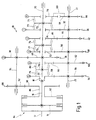
In Fig. 1 bezeichnet 10 insgesamt ein Ausführungsbeispiel des
erfindungsgemäßen Kraftfahrzeug-Stufengetriebes. Bei dem Getriebe
10 ist mit 12 noch eine Motorausgangswelle angedeutet,
die über eine übliche Trennkupplung 14 im Getriebeeingang mit
einer Getriebeeingangswelle 16 verbunden ist. Die Getriebeeingangswelle
16 ist an ihrem in der Figur rechten Ende mit einem
Lager 18 versehen, das zur Aufnahme einer Getriebeausgangswelle
20 dient, die sich in Verlängerung der Getriebeeingangswelle 16
erstreckt. Parallel zur Getriebeausgangswelle 20 ist eine Vorgelegewelle
22 angeordnet. Insoweit ist das Getriebe 10 von
herkömmlicher Bauart eines Vorgelegegetriebes.In Fig. 1, 10 designates an embodiment of the
Motor vehicle multi-speed transmission according to the invention. With the transmission
10 with 12 an engine output shaft is indicated,
which with a conventional separating clutch 14 in the transmission input
a
Auf der Getriebeausgangswelle 20 bzw. der Vorgelegewelle 22 befinden
sich ein erster Radsatz 30 für den ersten Gang mit Zahnrädern
32 und 34. Ein zweiter Radsatz 36 für den zweiten Gang
wird durch Zahnräder 38 und 40 gebildet. Ein dritter Radsatz 42
mit Zahnrädern 44 und 46 ist ebenso auf der Getriebeausgangswelle
20 bzw. der Vorgelegewelle 22 angeordnet wie ein vierter
Radsatz 48 für den vierten Gang mit Zahnrädern 50 und 52, ein
fünfter Radsatz 54 für den fünften Gang mit Zahnrädern 56 und
58, ein sechster Radsatz 60 für den sechsten Gang mit Zahnrädern
62 und 64 sowie schließlich ein siebter Radsatz 66 für den
Rückwärtsgang mit einem Zahnrad 68, einem Umkehrrad 69 sowie
einem Zahnrad 70.Located on the
Die Zahnräder 34, 46, 52, 58, 64 und 70 sind dabei als Losräder
ausgebildet, die auf der Getriebeausgangswelle 20 sitzen, während
die Zahnräder 32, 44, 50, 56, 62 und 68 als Festräder auf
der Vorgelegewelle 22 angeordnet sind.The
Zum Einlegen des ersten Ganges bzw. des Rückwärtsganges dient
eine erste Schiebemuffe 72 mit Schaltkupplungen 73 und 74. Zum
Einlegen des dritten bzw. des vierten Ganges dient eine zweite
Schiebemuffe 75 mit Schaltkupplungen 76 und 77. Zum Einlegen
des fünften bzw. des sechsten Ganges schließlich dient eine
dritte Schiebemuffe 78 mit Schaltkupplungen 79 und 80.Used to engage the first gear or the reverse gear
a first sliding
Wie man ferner erkennt, ist eine Reibungskupplung 82 konzentrisch
und axial neben der Trennkupplung 14 angeordnet, wobei
die Kupplungen 14, 82 gemeinsam eine Doppelkupplung 84 bilden
können. Die Reibungskupplung 82 ist mit einer Hohlwelle 86 verbunden,
die die Getriebeeingangswelle 16 koaxial umgibt. Von
der Hohlwelle 86 führt ein achter Radsatz 88 mit Zahnrädern 90
und 92 zu einer Nebenwelle 94, die sich parallel zu den Wellen
12, 16 und 22 erstreckt. Die Nebenwelle 94 trägt als Festrad
das Zahnrad 38 des zweiten Radsatzes 36 für den zweiten Gang,
dessen anderes Zahnrad 40 als Festrad auf der Getriebeausgangswelle
20 angeordnet ist.As can also be seen, a
Das Stufengetriebe 10 gemäß Fig. 1 arbeitet wie folgt:The step transmission 10 according to FIG. 1 operates as follows:
Beim Anfahren des Kraftfahrzeuges wird zunächst in herkömmlicher
Weise durch Betätigen der ersten Schiebemuffe 72 die erste
Schaltkupplung 73 geschlossen und damit das als Losrad ausgebildete
Zahnrad 34 des ersten Radsatzes 30 drehfest mit der
Getriebeausgangswelle 20 verbunden. Durch langsames Schließen
der Trennkupplung 14 wird nun das Antriebsmoment des Motors von
der Motorausgangswelle 12 über die Trennkupplung 14 auf die Getriebeeingangswelle
16 geleitet und von dort über den fünften
Radsatz 54 auf die Vorgelegewelle 22, von wo es über den ersten
Radsatz 30 wieder auf die Getriebeausgangswelle 20 gelangt.When starting the motor vehicle is first in conventional
Way by operating the first sliding
Wird nun vom ersten Gang in den zweiten Gang hochgeschaltet, so
wird die Reibungskupplung 82 geschlossen. Dadurch wird das
Drehmoment überschneidend von der Trennkupplung 14 auf die Reibungskupplung
82 übergeben. Zu einem bestimmten Zeitpunkt ist
infolge der sich einstellenden Drehzahlen der Drehmomentenpfad
des ersten Ganges lastlos, so daß der erste Gang durch Verschieben
der ersten Schiebemuffe 72 und Öffnen der ersten
Schaltkupplung 73 wieder herausgenommen werden kann. In entsprechender
Weise kann dann zum Hochschalten vom zweiten auf
den dritten Gang durch Verschieben der zweiten Schiebemuffe 75
die dritte Schaltkupplung 76 geschlossen und gleichzeitig die
Trennkupplung 14 ebenfalls wieder geschlossen werden. Dann wird
der Drehmomentenpfad für den zweiten Gang lastlos, so daß die
Reibungskupplung 82 wieder geöffnet werden kann. If you now shift up from first gear to second gear, so
the
Insgesamt können damit Lastschaltungen vom ersten in den zweiten, vom zweiten in den dritten, vom dritten in den zweiten und vom zweiten wieder in den ersten Gang dargestellt werden, und es wird auf diese Weise das Auftreten eines Schaltrucks vermieden. Die auftretenden Drehzahldifferenzen sind sehr gering, so daß sich nur ein geringer Verschleiß infolge geringer Verlustleistung einstellt. Die Betätigung der Kupplungen bzw. Schiebemuffen kann dabei sehr einfach ausgeführt werden.Overall, load switching from the first to the second, from the second to the third, from the third to the second and from the second to the first gear, and in this way the occurrence of a shift shock is avoided. The speed differences that occur are very small, so that there is little wear due to low power loss established. The actuation of the clutches or sliding sleeves can be done very easily.
Alternativ kann aber auch von Anfang an mit geschlossenen Kupplungen
14 und 82 für den ersten und den zweiten Gang angefahren
werden. Durch anschließendes Öffnen einer der beiden Kupplungen
14, 82 kann dann entweder im ersten Gang weitergefahren oder
gleich in den zweiten Gang hochgeschaltet werden.Alternatively, you can also use closed couplings from the
Beim Schalten der übrigen Gänge, nämlich der höheren Gänge 4., 5. und 6. sowie des Rückwärtsganges tritt in herkömmlicher Weise eine Zugkraftunterbrechung auf. Diese ist jedoch nahezu unmerklich, weil die übertragenen Drehmomente entsprechend gering sind. When shifting the other gears, namely the higher gears 4th, 5th and 6th and reverse gear occurs in a conventional manner an interruption in traction. However, this is almost imperceptible, because the transmitted torques are correspondingly low are.
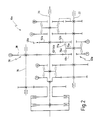
Bei einer Variante des Getriebes, wie sie mit 10a in Fig. 2
dargestellt ist, sind die Verhältnisse insoweit abgewandelt,
als die Losräder 46a für den dritten Gang und 52a für den vierten
Gang nunmehr auf der Vorgelegewelle 22 sitzen, die auch die
zweite Schiebemuffe 75a mit ihren Schaltkupplungen 76a, 77a
trägt. Eine weitere Besonderheit besteht darin, daß der dritte
Radsatz 42a für den dritten Gang nunmehr in derselben Radsatzebene
wie der zweite Radsatz 36 für den zweiten Gang liegt. In
diesem Falle sitzt auf der Getriebeausgangswelle 20 ein als
Festrad ausgebildetes Zahnrad 40/44a, das als gemeinsames
Zahnrad sowohl dem zweiten Radsatz 36 wie auch dem dritten Radsatz
42 zugehörig ist. Der vierte Radsatz 48a mit seinen Zahnrädern
50a, 52a für den vierten Gang ist ansonsten unverändert,
abgesehen davon, daß sich die Positionen der Zahnräder 50a, 52a
auf der Getriebeausgangswelle 20 bzw. der Vorgelegewelle 22
vertauscht haben.In a variant of the transmission, as shown at 10a in FIG. 2
the relationships have been modified to the extent that
than the idler gears 46a for the third gear and 52a for the fourth
Gear now sit on the
Das Getriebe 10a gemäß Fig. 2 hat folglich eine geringere axiale
Baulänge, weil gegenüber dem Ausführungsbeispiel gemäß
Fig. 1 eine Radsatzebene entfallen ist. Allerdings sind in diesem
Falle die Schiebemuffen mit den zugehörigen Betätigungseinrichtungen
(Schaltgabeln, Schaltstangen, Aktuatoren) auf zwei
Wellen verteilt.The
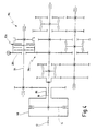
Bei einem dritten Ausführungsbeispiel 10b eines Stufengetriebes,
wie es in Fig. 3 dargestellt ist, wird auf die Getriebeanordnung
gemäß Fig. 2 zurückgegriffen. Eine Besonderheit besteht
beim Getriebe 10b darin, daß das auf der Nebenwelle 94 sitzende
Zahnrad 38b des zweiten Radsatzes 36b für den zweiten Gang als
Losrad ausgebildet ist. Zum drehfesten Verbinden des Zahnrades
38b mit der Nebenwelle 94 dient eine vierte Schiebemuffe 96 mit
Schaltkupplung 97. Diese Maßnahme hat den Sinn, die hohen Drehzahlen
zu vermeiden, die bei der Auslegung des Pfades von der
Reibungskupplung 82 in kleineren Gängen auftreten. Wird nämlich
die Schaltkupplung 97 geöffnet, so läuft nur das Zahnrad 38b,
während die Nebenwelle 94 leer läuft und damit auch die von ihr
über den achten Radsatz 88 angetriebene Reibungskupplung 82. In a third
Es versteht sich dabei, daß anstelle der Schiebemuffe 96 mit
Schaltkupplung 97 auch ein entsprechender Freilauf vorgesehen
werden kann, der zweckmäßigerweise schaltbar sein sollte.It goes without saying that instead of the sliding
Schließlich zeigt Fig. 4 noch ein viertes Ausführungsbeispiel
10c eines derartigen Getriebes, dessen Konfiguration weitgehend
demjenigen von Fig. 2 und 3 entspricht. Das Getriebe 10c unterscheidet
sich davon durch folgende Besonderheiten:Finally, Fig. 4 shows a
Zunächst ist das Zahnrad 38c des zweiten Radsatzes 36c für den
zweiten Gang wiederum als Losrad auf der Nebenwelle 94 ausgebildet.
Zum drehfesten Verbinden des Zahnrades 38c mit der Nebenwelle
94 dient jedoch in diesem Falle die Reibungskupplung
82c, die bei dem in Fig. 4 dargestellten Ausführungsbeispiel
10c des Getriebes vom Getriebeeingang an diese Stelle verlegt
wurde. Folglich ist bei diesem Ausführungsbeispiel 10c die
Trennkupplung 14 als herkömmliche Einzelkupplung ausgebildet,
bei der lediglich das mit der Motorausgangswelle 12 umlaufende
Kupplungsgehäuse 98 mit der Hohlwelle 86 verbunden ist.First, the
Im übrigen entspricht die Funktion des Getriebes 10c gemäß
Fig. 4 derjenigen des Getriebes 10 gemäß Fig. 1.Otherwise, the function of the
Es versteht sich, daß die in den Figuren dargestellten Betätigungselemente für die Kupplungen und Schiebemuffen hydraulisch, pneumatisch, elektromechanisch, elektromagnetisch oder sonstwie fremdkraftbetätigt sein können. Ferner können die Getriebe in herkömmlicher Längsbauweise oder auch in Front-Quer-Bauweise ausgeführt sein.It is understood that the actuators shown in the figures for the couplings and sliding sleeves hydraulic, pneumatic, electromechanical, electromagnetic or otherwise can be powered. Furthermore, the gear in conventional longitudinal construction or also front-transverse construction be executed.
Claims (16)
- A motor vehicle stepped counter shaft transmission, comprising a transmission input shaft (16) drivable by an engine output shaft (12) via a separating clutch (14), a transmission output shaft (20) arranged collinearly with said transmission input shaft (16), and a counter shaft (22) arranged parallel to said transmission output shaft (20), a plurality of gearwheel sets (30, 36, 42, 48, 54, 60, 66) for establishing gears (1., 2., 3., 4., 5., 6., R) of said transmission (10), wherein gearwheel sets (30, 42, 48, 54, 60, 66) each comprise a loose wheel (34, 46, 52, 58, 64, 70), said loose wheels (34, 46, 52, 58, 64, 70) being arranged on a shaft (20; 22) and being adapted to be rigidly connected to said shaft (20; 22) by means of gearshift clutches (73, 74, 76, 77, 79, 80) for shifting into gears (1., 3., 4., 5., 6., R), wherein a gearwheel set (36) of a further gear (2.) being adapted to be shifted by means of a friction clutch (82), and wherein, eventually, for reducing a gearshift jolt when shifting from one gear to another, said friction clutch (82) is adapted to be closed when one of said gearshift clutches (73, 74, 76, 77, 79, 80) is being activated, wherein a toothed wheel (38) of said gearwheel set (36) of said further gear (2.) being arranged on an additional shaft (94) parallel to said transmission output shaft (20), and wherein a torque-transmitting connection from said engine output shaft (12) to said gearwheel set (36) of said further gear (2.) being establishable via said friction clutch (82), wherein said further gear is the second gear (2.), characterized in that said further gear (2.) is the only gear that can be shifted via said friction clutch (82).
- The transmission of claim 1, characterized in that said separating clutch (14) and said friction clutch (82) are structurally integrated as a double clutch (84).
- The transmission of claim 2, characterized in that said friction clutch (82) cooperates with a hollow shaft (86) of said double clutch, and wherein said hollow shaft (86) and said additional shaft (94) being interconnected via a gearwheel set (88).
- The transmission of claim 1, characterized in that said friction clutch (82c) is arranged on said additional shaft (94), and is provided for connecting a toothed wheel (38c) of said gearwheel set (36c) of said further gear (2.), said toothed wheel (38c) being a loose wheel and being rotatably arranged on said additional shaft (94).
- The transmission of any or multiple of claims 1 to 3, characterized in that one of said toothed wheels (38b; 38c) of said gearwheel set (36b; 36c) of said further gear (2.) is arranged as a loose wheel rotatably arranged on said additional shaft (94), and that a clutch (82c; 97) is provided, for rigidly connecting that toothed wheel (38b, 38c) with said additional shaft (94).
- The transmission of claim 5, characterized in that said clutch is configured as a gearshift clutch (97) and is adapted to be actuated by means of a shift sleeve (96).
- The transmission of claim 5, characterized in that said clutch is configured as a friction clutch (82c).
- The transmission of one or multiple of the preceding claims, characterized in that all of said loose wheels (34, 46, 52, 58, 64, 70) are arranged on said transmission output shaft (20).
- The transmission of claim 8, characterized in that a toothed wheel (40) of said gearwheel set (36) of said further gear (2.) is configured as a fixed wheel on said transmission output shaft (20).
- The transmission of claim 8 or 9, characterized in that said gearwheel sets (30, 36, 42, 48, 54, 60, 66) of said gears (1., 2., 3., 4., 5., 6., R) are arranged in a sequence 5.-6.-2.-4.-3.-1.-R, as viewed from an input end of said transmission.
- The transmission of one or multiple of claims 1 to 7, characterized in that a first plurality of loose wheels (34, 58, 64, 70) is arranged on said transmission output shaft (20) whereas a second plurality of loose wheels (46a, 52a) is arranged on said counter shaft (22).
- The transmission of claim 11, characterized in that said gearwheel sets (36, 42a) of said further gear (2.) and of one further gear (3.) have one toothed wheel (40/44a) in common.
- The transmission of claim 12, characterized in that said common toothed wheel (40/44a) is arranged on said transmission output shaft (20).
- The transmission of claim 12 or 13, characterized in that said common toothed wheel (40/44a) is configured as a fixed wheel.
- The transmission of one or multiple of claims 11 to 14, characterized in that said gearwheel sets (30, 36, 42, 48, 54, 60, 66) of said gears (1., 2., 3., 4., 5., 6., R) are arranged in a sequence 5.-6.-2./3.-4.-1.-R, as viewed from the input end of said transmission.
- The transmission of one or multiple of claims 1 to 15, characterized in that, for starting said vehicle from stand still, said clutches (14, 82) of said first (1.) and said second (2.) gear are adapted to be activated simultaneously.
Applications Claiming Priority (2)
| Application Number | Priority Date | Filing Date | Title |
|---|---|---|---|
| DE19802820A DE19802820C1 (en) | 1998-01-26 | 1998-01-26 | Motor vehicle step transmission |
| DE19802820 | 1998-01-26 |
Publications (2)
| Publication Number | Publication Date |
|---|---|
| EP0933558A1 EP0933558A1 (en) | 1999-08-04 |
| EP0933558B1 true EP0933558B1 (en) | 2003-04-09 |
Family
ID=7855674
Family Applications (1)
| Application Number | Title | Priority Date | Filing Date |
|---|---|---|---|
| EP99101287A Expired - Lifetime EP0933558B1 (en) | 1998-01-26 | 1999-01-25 | Stepped automotive gearbox |
Country Status (4)
| Country | Link |
|---|---|
| US (1) | US6095001A (en) |
| EP (1) | EP0933558B1 (en) |
| JP (1) | JPH11264449A (en) |
| DE (2) | DE19802820C1 (en) |
Cited By (3)
| Publication number | Priority date | Publication date | Assignee | Title |
|---|---|---|---|---|
| DE102009056045A1 (en) * | 2009-11-27 | 2011-06-09 | GM Global Technology Operations LLC, ( n. d. Ges. d. Staates Delaware ), Detroit | Two-shaft transmission of a motor vehicle |
| DE102018211958A1 (en) | 2018-07-18 | 2020-01-23 | Magna Pt B.V. & Co. Kg | Double clutch |
| DE102019202598A1 (en) * | 2019-02-26 | 2020-08-27 | Magna Pt B.V. & Co. Kg | Double clutch |
Families Citing this family (37)
| Publication number | Priority date | Publication date | Assignee | Title |
|---|---|---|---|---|
| JP2001213201A (en) * | 1999-12-17 | 2001-08-07 | Getrag Getriebe & Zahnradfab Hermann Hagenmeyer Gmbh & Co | Automatic drive mechanism train for automobile and method for controlling drive mechanism train |
| JP3294230B2 (en) * | 2000-02-22 | 2002-06-24 | 株式会社日立製作所 | Vehicle control device, vehicle control method, transmission |
| WO2001088409A2 (en) * | 2000-05-17 | 2001-11-22 | Luk Lamellen Und Kupplungsbau Beteiligungs Kg | Gearbox comprising a clutch and a method for operating a clutch |
| US6364809B1 (en) * | 2000-05-18 | 2002-04-02 | Daimlerchrysler Corporation | Clutch control system for upshift of an electro-mechanical automatic transmission |
| JP3293613B2 (en) | 2000-06-23 | 2002-06-17 | 株式会社日立製作所 | Vehicle control device, vehicle control method, transmission |
| DE10043060B4 (en) * | 2000-09-01 | 2016-07-07 | Volkswagen Ag | Method for controlling two clutches of a motor vehicle |
| DE10140745A1 (en) * | 2000-09-15 | 2002-05-02 | Luk Lamellen & Kupplungsbau | Actuator for friction clutches in the drive line of an automotive vehicle, e.g. tourist vehicle, has arrangement ensuring even torque transfer to wheels from parallel torque transfer paths in the automatic electrohydraulic gearbox |
| EP1354151A1 (en) * | 2001-01-04 | 2003-10-22 | Eaton Corporation | Gearbox with intermeshing gears mounted on one shaft |
| US6499370B2 (en) * | 2001-01-10 | 2002-12-31 | New Venture Gear, Inc. | Twin clutch automated transaxle with motor/generator synchronization |
| US6490945B2 (en) * | 2001-01-10 | 2002-12-10 | New Venture Gear, Inc. | Twin clutch automated transmission with integrated transfer case |
| JP2002276797A (en) * | 2001-03-15 | 2002-09-25 | Hitachi Ltd | Automatic transmission |
| US6672180B2 (en) * | 2001-04-05 | 2004-01-06 | New Venture Gear, Inc. | Manual transmission with upshift and downshift synchronization clutches |
| FR2831234B1 (en) * | 2001-10-19 | 2004-03-12 | Renault | TORQUE CHANGE CONTROL METHOD AND CORRESPONDING AUTOMATED TRANSMISSION |
| JP4323132B2 (en) * | 2002-03-15 | 2009-09-02 | 株式会社日立製作所 | Automobile control method, automobile control device, transmission, transmission control device, and vehicle system |
| US6860168B1 (en) | 2002-04-16 | 2005-03-01 | Fuji Jukogyo Kabushiki Kaisha | Automatic transmission for vehicle |
| JP4260522B2 (en) * | 2002-04-24 | 2009-04-30 | 本田技研工業株式会社 | Power transmission device |
| DE10243278A1 (en) * | 2002-09-18 | 2004-03-25 | Volkswagen Ag | Device for synchronizing a double clutch transmission |
| US6886424B2 (en) * | 2003-06-25 | 2005-05-03 | Ford Global Technologies, Llc | Layshaft automatic transmission having power-on shifting |
| DE10361333A1 (en) * | 2003-12-18 | 2005-07-14 | Getrag Innovations Gmbh | Automatic change gear |
| DE102004002283A1 (en) | 2004-01-16 | 2005-08-18 | Zf Friedrichshafen Ag | Drive device with a manual transmission |
| DE102004005652A1 (en) * | 2004-02-04 | 2005-08-25 | Basf Ag | Flowable polyester molding compounds |
| DE102005004339B4 (en) * | 2005-01-25 | 2009-01-08 | Getrag Getriebe- Und Zahnradfabrik Hermann Hagenmeyer Gmbh & Cie Kg | Use of a step change gearbox and method for controlling such |
| KR100828673B1 (en) * | 2005-12-21 | 2008-05-09 | 현대자동차주식회사 | Six-speed manual transmission |
| JP4939049B2 (en) * | 2005-12-28 | 2012-05-23 | 本田技研工業株式会社 | Shift control method in twin clutch gear transmission |
| DE102008001407A1 (en) * | 2008-04-28 | 2009-10-29 | Zf Friedrichshafen Ag | Multi-group transmission of a motor vehicle |
| DE102008001646A1 (en) | 2008-05-08 | 2009-11-12 | Zf Friedrichshafen Ag | Multi-group transmission of a motor vehicle |
| DE102008002069A1 (en) * | 2008-05-29 | 2009-12-03 | Zf Friedrichshafen Ag | Multi-speed powershift transmission |
| US8505400B2 (en) * | 2009-04-02 | 2013-08-13 | GM Global Technology Operations LLC | Dual clutch five speed transmission |
| DE102009003108B4 (en) * | 2009-05-14 | 2017-08-10 | Zf Friedrichshafen Ag | Drive arrangement with two input-side couplings |
| WO2012019586A1 (en) * | 2010-08-12 | 2012-02-16 | Schaeffler Technologies Gmbh & Co. Kg | Method for operating an automated dual-clutch transmission |
| EP2549152B1 (en) * | 2011-07-20 | 2013-10-16 | C.R.F. Società Consortile per Azioni | Gear change device for a motor vehicle |
| CN102537318A (en) * | 2012-02-29 | 2012-07-04 | 鲁伟 | AMT automobile gearbox with gear shifting control shaft and gear shifting method thereof |
| KR20130116998A (en) * | 2012-04-17 | 2013-10-25 | (주)테너지 | Automated manual transmission |
| CN102748465A (en) * | 2012-07-18 | 2012-10-24 | 鲁伟 | Gearbox with shifting auxiliary shaft and shifting method of the gearbox |
| KR101408453B1 (en) * | 2012-10-12 | 2014-06-17 | 강명구 | Multiple Hydraulic Wet Clutch Transmission for vehicles |
| JP6255980B2 (en) * | 2013-12-20 | 2018-01-10 | スズキ株式会社 | Transmission |
| DE102014011921B4 (en) * | 2014-08-12 | 2016-03-17 | Audi Ag | Speed change gearbox for a motor vehicle |
Family Cites Families (18)
| Publication number | Priority date | Publication date | Assignee | Title |
|---|---|---|---|---|
| US2599801A (en) * | 1949-06-11 | 1952-06-10 | Borg Warner | Double countershaft transmission |
| DE967545C (en) * | 1953-10-13 | 1957-11-21 | Georg Heim | Gear change transmission, especially for vehicles with internal combustion engines |
| DE3131139C2 (en) * | 1981-08-06 | 1985-09-12 | Zahnradfabrik Friedrichshafen Ag, 7990 Friedrichshafen | Spur gear change gear |
| US4463621A (en) * | 1981-12-23 | 1984-08-07 | Ford Motor Company | Multiple countershaft automatic transmission |
| DE3812359C3 (en) * | 1987-12-19 | 1993-01-14 | Getrag Getriebe Zahnrad | DOUBLE CLUTCH |
| DE3812327A1 (en) * | 1987-12-19 | 1989-06-29 | Getrag Getriebe Zahnrad | Method for the adjustment of a double clutch transmission and double clutch transmission |
| IT1219343B (en) * | 1988-05-31 | 1990-05-11 | Fiatgeotech | SPEED CHANGE FOR A VEHICLE PARTICULARLY AN AGRICULTURAL TRACTOR |
| DE3926570C2 (en) * | 1989-08-11 | 1994-11-24 | Daimler Benz Ag | Gear change transmission with two countershaft transmissions for motor vehicles |
| DE59107123D1 (en) * | 1990-09-05 | 1996-02-01 | Valentin Balass | DOUBLE CLUTCH SPEED GEARBOX FOR MOTOR VEHICLES |
| DE4031571A1 (en) * | 1990-10-05 | 1992-04-09 | Daimler Benz Ag | METHOD FOR SHIFTING A MULTIPLE-WAY GEAR GEAR WITH ANY GEAR BY A GEAR CLUTCH WITH YOUR SHAFT COUPLABLE LOCKING WHEELS |
| DE4031851C2 (en) * | 1990-10-08 | 2001-08-02 | Volkswagen Ag | Step change gear |
| DE4401812C2 (en) * | 1993-02-03 | 2002-01-24 | Volkswagen Ag | Speed gearbox |
| JPH07301302A (en) * | 1994-04-28 | 1995-11-14 | Aisin Aw Co Ltd | Power transmission device for vehicle |
| US5603242A (en) * | 1995-07-11 | 1997-02-18 | Caterpillar Inc. | Direct drive transmission apparatus and method for controlling shift |
| JP3531301B2 (en) * | 1995-07-25 | 2004-05-31 | トヨタ自動車株式会社 | Twin clutch transmission |
| DE19548622C1 (en) * | 1995-12-23 | 1997-05-07 | Ford Werke Ag | Gear change gearbox for motor vehicles that can be switched without interruption in tractive power |
| BR9707990A (en) * | 1996-03-08 | 1999-07-27 | Volvo Lastvagnar Ab | Motor vehicle gearbox |
| DE19631983C1 (en) * | 1996-08-08 | 1998-02-12 | Volkswagen Ag | Method for shifting a double clutch transmission and double clutch transmission with synchronizing device |
-
1998
- 1998-01-26 DE DE19802820A patent/DE19802820C1/en not_active Expired - Fee Related
-
1999
- 1999-01-22 US US09/235,953 patent/US6095001A/en not_active Expired - Fee Related
- 1999-01-25 EP EP99101287A patent/EP0933558B1/en not_active Expired - Lifetime
- 1999-01-25 JP JP11016056A patent/JPH11264449A/en active Pending
- 1999-01-25 DE DE59904901T patent/DE59904901D1/en not_active Expired - Fee Related
Cited By (4)
| Publication number | Priority date | Publication date | Assignee | Title |
|---|---|---|---|---|
| DE102009056045A1 (en) * | 2009-11-27 | 2011-06-09 | GM Global Technology Operations LLC, ( n. d. Ges. d. Staates Delaware ), Detroit | Two-shaft transmission of a motor vehicle |
| DE102018211958A1 (en) | 2018-07-18 | 2020-01-23 | Magna Pt B.V. & Co. Kg | Double clutch |
| DE102019202598A1 (en) * | 2019-02-26 | 2020-08-27 | Magna Pt B.V. & Co. Kg | Double clutch |
| DE102019202598B4 (en) * | 2019-02-26 | 2020-11-19 | Magna Pt B.V. & Co. Kg | Double clutch |
Also Published As
| Publication number | Publication date |
|---|---|
| JPH11264449A (en) | 1999-09-28 |
| DE59904901D1 (en) | 2003-05-15 |
| EP0933558A1 (en) | 1999-08-04 |
| DE19802820C1 (en) | 1999-12-16 |
| US6095001A (en) | 2000-08-01 |
Similar Documents
| Publication | Publication Date | Title |
|---|---|---|
| EP0933558B1 (en) | Stepped automotive gearbox | |
| EP0195452B1 (en) | Contunuously variable compound power shift transmission of the range-speed type with multiple power path | |
| EP1013966B1 (en) | Toothed speed-changing gearing with two parallel transmission paths | |
| DE102005012535B4 (en) | Multi-speed power transmissions | |
| DE4335995B4 (en) | Automatic transmission with intermediate shaft and double clutch | |
| EP2195552B1 (en) | Variable-speed gear wheel transmission comprising two input shafts and two clutches | |
| EP0780596B1 (en) | Powershift type countershaft transmission for vehicles | |
| DE102007010292B4 (en) | Switching device for a transmission, in particular a dual clutch change gear | |
| EP2128495B1 (en) | Motor vehicle multi-group drive | |
| EP1141580B1 (en) | Gear wheel variable transmission with two sub-gears arranged parallel to each other in the power flow | |
| EP2914874B1 (en) | Double clutch transmission | |
| WO2006084555A1 (en) | Twin clutch transmission | |
| DE19853824A1 (en) | Automated motor vehicle drive train has parallel force transfer paths; second force transfer path transfers torque to drive shaft during force transfer interruption in first transfer path | |
| WO2001088409A2 (en) | Gearbox comprising a clutch and a method for operating a clutch | |
| DE102006028798A1 (en) | Double clutch | |
| DE102008002295A1 (en) | Multi-group transmission of a motor vehicle | |
| DE19908602A1 (en) | Automated drive train for a motor vehicle and method for controlling a drive train | |
| WO2008092566A1 (en) | Shift transmission with dual clutch | |
| EP3259500A1 (en) | Dual clutch transmission for a motor vehicle | |
| WO2003025431A1 (en) | Automatic multi-speed vehicle gearbox | |
| EP3126710B1 (en) | Gearshift transmission for a motor vehicle | |
| DE3512523C1 (en) | Infinitely variable split-torque compound power-shift transmission with range changes | |
| DE102007004291A1 (en) | Gearbox for motor vehicle, has dual clutch switchable between conditions, in which gearwheels are torque-proofly coupled at input shafts, and third condition, in which gearwheel are coupled to each other at input shafts and gearwheels | |
| DE4236671C1 (en) | Staglessly working hydrostatic-mechanical load switch gear - comprises four-shaft gearwheel circulating gear, stagelessly adjustable hydrostatic gear comprising gearwheel switch stages, and switch couplings | |
| EP2061979A1 (en) | Dual clutch transmission |
Legal Events
| Date | Code | Title | Description |
|---|---|---|---|
| PUAI | Public reference made under article 153(3) epc to a published international application that has entered the european phase |
Free format text: ORIGINAL CODE: 0009012 |
|
| AK | Designated contracting states |
Kind code of ref document: A1 Designated state(s): DE ES FR GB IT |
|
| AX | Request for extension of the european patent |
Free format text: AL;LT;LV;MK;RO;SI |
|
| 17P | Request for examination filed |
Effective date: 19991215 |
|
| AKX | Designation fees paid |
Free format text: DE ES FR GB IT |
|
| 17Q | First examination report despatched |
Effective date: 20010919 |
|
| RAP1 | Party data changed (applicant data changed or rights of an application transferred) |
Owner name: GETRAG GETRIEBE- UND ZAHNRADFABRIK HERMANN HAGENME |
|
| GRAH | Despatch of communication of intention to grant a patent |
Free format text: ORIGINAL CODE: EPIDOS IGRA |
|
| GRAH | Despatch of communication of intention to grant a patent |
Free format text: ORIGINAL CODE: EPIDOS IGRA |
|
| GRAA | (expected) grant |
Free format text: ORIGINAL CODE: 0009210 |
|
| AK | Designated contracting states |
Designated state(s): DE ES FR GB IT |
|
| PG25 | Lapsed in a contracting state [announced via postgrant information from national office to epo] |
Ref country code: GB Free format text: LAPSE BECAUSE OF FAILURE TO SUBMIT A TRANSLATION OF THE DESCRIPTION OR TO PAY THE FEE WITHIN THE PRESCRIBED TIME-LIMIT Effective date: 20030409 |
|
| REG | Reference to a national code |
Ref country code: GB Ref legal event code: FG4D Free format text: NOT ENGLISH |
|
| ET | Fr: translation filed | ||
| GBV | Gb: ep patent (uk) treated as always having been void in accordance with gb section 77(7)/1977 [no translation filed] |
Effective date: 20030409 |
|
| PG25 | Lapsed in a contracting state [announced via postgrant information from national office to epo] |
Ref country code: ES Free format text: LAPSE BECAUSE OF FAILURE TO SUBMIT A TRANSLATION OF THE DESCRIPTION OR TO PAY THE FEE WITHIN THE PRESCRIBED TIME-LIMIT Effective date: 20031030 |
|
| PGFP | Annual fee paid to national office [announced via postgrant information from national office to epo] |
Ref country code: FR Payment date: 20040109 Year of fee payment: 6 |
|
| PLBE | No opposition filed within time limit |
Free format text: ORIGINAL CODE: 0009261 |
|
| STAA | Information on the status of an ep patent application or granted ep patent |
Free format text: STATUS: NO OPPOSITION FILED WITHIN TIME LIMIT |
|
| PGFP | Annual fee paid to national office [announced via postgrant information from national office to epo] |
Ref country code: DE Payment date: 20040303 Year of fee payment: 6 |
|
| 26N | No opposition filed |
Effective date: 20040112 |
|
| PG25 | Lapsed in a contracting state [announced via postgrant information from national office to epo] |
Ref country code: IT Free format text: LAPSE BECAUSE OF NON-PAYMENT OF DUE FEES Effective date: 20050125 |
|
| PG25 | Lapsed in a contracting state [announced via postgrant information from national office to epo] |
Ref country code: DE Free format text: LAPSE BECAUSE OF NON-PAYMENT OF DUE FEES Effective date: 20050802 |
|
| PG25 | Lapsed in a contracting state [announced via postgrant information from national office to epo] |
Ref country code: FR Free format text: LAPSE BECAUSE OF NON-PAYMENT OF DUE FEES Effective date: 20050930 |
|
| REG | Reference to a national code |
Ref country code: FR Ref legal event code: ST |