EP0932744B1 - Verfahren zur herstellung von lichtleitplatten - Google Patents
Verfahren zur herstellung von lichtleitplatten Download PDFInfo
- Publication number
- EP0932744B1 EP0932744B1 EP97944893A EP97944893A EP0932744B1 EP 0932744 B1 EP0932744 B1 EP 0932744B1 EP 97944893 A EP97944893 A EP 97944893A EP 97944893 A EP97944893 A EP 97944893A EP 0932744 B1 EP0932744 B1 EP 0932744B1
- Authority
- EP
- European Patent Office
- Prior art keywords
- plastic
- process according
- strips
- optical diffuser
- diffuser plates
- Prior art date
- Legal status (The legal status is an assumption and is not a legal conclusion. Google has not performed a legal analysis and makes no representation as to the accuracy of the status listed.)
- Expired - Lifetime
Links
- 230000003287 optical effect Effects 0.000 title claims abstract 5
- 238000000034 method Methods 0.000 title claims description 12
- 238000004519 manufacturing process Methods 0.000 title description 4
- 229920003023 plastic Polymers 0.000 claims abstract description 52
- 239000004033 plastic Substances 0.000 claims abstract description 46
- HIZCTWCPHWUPFU-UHFFFAOYSA-N Glycerol tribenzoate Chemical compound C=1C=CC=CC=1C(=O)OCC(OC(=O)C=1C=CC=CC=1)COC(=O)C1=CC=CC=C1 HIZCTWCPHWUPFU-UHFFFAOYSA-N 0.000 claims abstract description 23
- 239000004417 polycarbonate Substances 0.000 claims abstract description 4
- 229920000515 polycarbonate Polymers 0.000 claims abstract description 4
- 229920000193 polymethacrylate Polymers 0.000 claims abstract 3
- 239000011159 matrix material Substances 0.000 claims description 7
- -1 polypropylene Polymers 0.000 claims description 6
- 229920000642 polymer Polymers 0.000 claims description 5
- 239000004698 Polyethylene Substances 0.000 claims description 3
- 229920000573 polyethylene Polymers 0.000 claims description 3
- 239000004743 Polypropylene Substances 0.000 claims description 2
- 229920001155 polypropylene Polymers 0.000 claims description 2
- 229920001169 thermoplastic Polymers 0.000 claims description 2
- 239000004416 thermosoftening plastic Substances 0.000 claims description 2
- YCKRFDGAMUMZLT-UHFFFAOYSA-N Fluorine atom Chemical compound [F] YCKRFDGAMUMZLT-UHFFFAOYSA-N 0.000 claims 1
- 239000004952 Polyamide Substances 0.000 claims 1
- 229910052731 fluorine Inorganic materials 0.000 claims 1
- 239000011737 fluorine Substances 0.000 claims 1
- 229920002647 polyamide Polymers 0.000 claims 1
- 239000012815 thermoplastic material Substances 0.000 claims 1
- 238000000926 separation method Methods 0.000 description 6
- 230000000694 effects Effects 0.000 description 5
- 239000000463 material Substances 0.000 description 5
- 238000005516 engineering process Methods 0.000 description 4
- 238000001125 extrusion Methods 0.000 description 4
- 239000003795 chemical substances by application Substances 0.000 description 2
- 239000004811 fluoropolymer Substances 0.000 description 2
- 229920002313 fluoropolymer Polymers 0.000 description 2
- 229920003229 poly(methyl methacrylate) Polymers 0.000 description 2
- 239000004926 polymethyl methacrylate Substances 0.000 description 2
- 229920006099 Vestamid® Polymers 0.000 description 1
- 230000009286 beneficial effect Effects 0.000 description 1
- 230000015572 biosynthetic process Effects 0.000 description 1
- 238000001816 cooling Methods 0.000 description 1
- 229920001577 copolymer Polymers 0.000 description 1
- 238000009792 diffusion process Methods 0.000 description 1
- 239000002803 fossil fuel Substances 0.000 description 1
- 239000011521 glass Substances 0.000 description 1
- 238000005286 illumination Methods 0.000 description 1
- 238000011835 investigation Methods 0.000 description 1
- 210000000056 organ Anatomy 0.000 description 1
- 230000007704 transition Effects 0.000 description 1
- 239000012780 transparent material Substances 0.000 description 1
- 229920006352 transparent thermoplastic Polymers 0.000 description 1
- 238000004804 winding Methods 0.000 description 1
Images

Classifications
-
- F—MECHANICAL ENGINEERING; LIGHTING; HEATING; WEAPONS; BLASTING
- F21—LIGHTING
- F21S—NON-PORTABLE LIGHTING DEVICES; SYSTEMS THEREOF; VEHICLE LIGHTING DEVICES SPECIALLY ADAPTED FOR VEHICLE EXTERIORS
- F21S11/00—Non-electric lighting devices or systems using daylight
-
- E—FIXED CONSTRUCTIONS
- E06—DOORS, WINDOWS, SHUTTERS, OR ROLLER BLINDS IN GENERAL; LADDERS
- E06B—FIXED OR MOVABLE CLOSURES FOR OPENINGS IN BUILDINGS, VEHICLES, FENCES OR LIKE ENCLOSURES IN GENERAL, e.g. DOORS, WINDOWS, BLINDS, GATES
- E06B9/00—Screening or protective devices for wall or similar openings, with or without operating or securing mechanisms; Closures of similar construction
- E06B9/24—Screens or other constructions affording protection against light, especially against sunshine; Similar screens for privacy or appearance; Slat blinds
-
- G—PHYSICS
- G02—OPTICS
- G02B—OPTICAL ELEMENTS, SYSTEMS OR APPARATUS
- G02B5/00—Optical elements other than lenses
-
- E—FIXED CONSTRUCTIONS
- E06—DOORS, WINDOWS, SHUTTERS, OR ROLLER BLINDS IN GENERAL; LADDERS
- E06B—FIXED OR MOVABLE CLOSURES FOR OPENINGS IN BUILDINGS, VEHICLES, FENCES OR LIKE ENCLOSURES IN GENERAL, e.g. DOORS, WINDOWS, BLINDS, GATES
- E06B9/00—Screening or protective devices for wall or similar openings, with or without operating or securing mechanisms; Closures of similar construction
- E06B9/24—Screens or other constructions affording protection against light, especially against sunshine; Similar screens for privacy or appearance; Slat blinds
- E06B2009/2417—Light path control; means to control reflection
Definitions
- the invention relates to light guide plates made of transparent plastic, which for better lighting of rooms with daylight.
- U.S. 4,989,952 describes a light guide plate that consists of a transparent material with a number of parallel incisions consists.
- the difference to the plate according to the invention is that that the material that comes from the plate of the prior art A laser beam is removed, which is the same material from which the plate exists.
- the present invention has set itself the task of remedying this create.
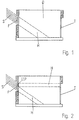
- So-called light-guiding elements are used to solve the problem used which according to the procedure according to the subject of independent claim are made. Collect these light guide elements - over part of the Window surface - the daylight and direct it into the depth of the room or against the ceiling (Fig. 2). The light-guiding elements thus cause Redirecting the daylight, which falls steeply from the outside, into the interior of the Space.
- Fig. 2 represents the room shown in Fig. 1 now equipped with the light guide element according to the invention in a part of the window area.
- the reference symbol LLP stands for the light guide plate. The remaining reference numbers correspond to those in FIG. 1.
- an LLP light guide plate is used following structure proposed (Fig. 3):
- plastic B with the refractive index n B are inserted, preferably extruded, with the proviso that plastic A is not compatible with plastic B and Plastic A separates from plastic B. This separation is favored by the presence of a yield point in plastic B.
- the light-guiding effect can be achieved by both features, which are different per se be achieved.
- the interface of the materials or the material transition is accordingly either only due to the difference of the Refractive index noticeable or it is - when the separation gap is formed - as reflecting surface very clearly recognizable.
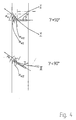
- the incident light beam passes through the interface. Since the preferred production mode of the light guide plates LLP is the coextrusion of the plate together with the inserted thin strips, there are primarily co-extrusible, transparent thermoplastics that are incompatible with the plastic A of the plate. The greater the difference in refractive index, the greater the critical angle ⁇ G and thus the effectiveness of the system. Sufficient effectiveness of the system, even at small critical angles ⁇ G, can be achieved by tilting the plastic strips ( ⁇ ⁇ 90 °). The angle of incidence on the interface ⁇ E is reduced by the inclination of the strips (case II in FIG. 4).
- plastics A can be, for example, polymethyl methacrylate (PMMA and copolymers) or polycarbonate (PC) are used as Plastic B are the polymers mentioned above. It has been found in attempts to manufacture light guide plates like this have been described above, shown that yet another feature leads to unexpected light guide effects. It was found that at Incompatibility of plastic B with plastic A, if so thin band of plastic B no adhesion with the matrix, the Has plastic A and is separated from it by a thin gap that Light guiding effect is increased. The detachment of the plastic band the plastic B of the matrix polymer A is easy to recognize optically:
- the plastic tape seems to have a reflective surface. This is a sign that the thin gap along the surface of the tape has caused a pronounced total reflection.
- the refractive indices of air and the matrix plastic A differ much more, than that of plastic B and the matrix plastic A, corresponding to the formula given above, which explains the high total reflection.
- the separation of the two plastics A and B from each other is done by different thermal expansion coefficients favored. she takes place when the extrusion mass cools.
- the tape should be there preferably shrink more than the matrix, i.e. Plastic B should have higher thermal expansion coefficients than plastic A. Already slight differences in the coefficient of thermal expansion ⁇ 0.001% lead to the effect according to the invention.
- the refractive index of plastic A can preferably be higher, but also the same or lower than that of plastic B.
- the total reflection caused by the formation of the separation point is strong enough in any case to produce an impressive light-guiding effect.
- the width of the separation gap must be greater than 1 ⁇ m.
- the thickness of the light guide plates LLP is generally in the range 2 to 20 mm.
- the inserted, preferably extruded, strips made of plastic B generally have a thickness of 0.05-0.5 mm and a width of 50 to 95% based on the thickness of the plate made of plastic A.
- the strips of plastic B are regularly arranged in the plastic plates A at mutual intervals of 2 to 40 mm.
- the remaining dimensions of the light guide plates LLP are expediently adapted to the glazing units, in particular the window or door formats. A limitation of the dimensions due to the extrusion technology used is generally not to be expected.
- the light guide plates according to the invention can be used successfully for better Illumination of rooms, u. a. Workshops, halls, cellars, vaults, Manholes, possibly also vehicles such as ships and. ⁇ . used become. Your application can not only save energy but also contribute to the better ergonomic design of workspaces.
Landscapes
- Engineering & Computer Science (AREA)
- Structural Engineering (AREA)
- Physics & Mathematics (AREA)
- General Engineering & Computer Science (AREA)
- General Physics & Mathematics (AREA)
- Optics & Photonics (AREA)
- Architecture (AREA)
- Life Sciences & Earth Sciences (AREA)
- Sustainable Development (AREA)
- Civil Engineering (AREA)
- Extrusion Moulding Of Plastics Or The Like (AREA)
- Laminated Bodies (AREA)
- Light Guides In General And Applications Therefor (AREA)
- Non-Portable Lighting Devices Or Systems Thereof (AREA)
- Planar Illumination Modules (AREA)
- Optical Head (AREA)
- Optical Communication System (AREA)
- Holo Graphy (AREA)
Description
Tritt ein Licht auf eine Lichtleitplatte LLP der beschriebenen Art, so gelten an der Grenzfläche zwischen den Kunststoffen A und dem Luftspalt die Gesetzt der Totalreflexion. Der Grenzwinkel der Totalreflexion αG hängt nur von den Brechungsindices der beiden Kunststoffe ab.
Die Dicke der Lichtleitplatten LLP liegt im allgemeinen im Bereich 2 bis 20 mm. Die eingefügten, vorzugsweise einextrudierten Bänder aus dem Kunststoff B besitzen in der Regel eine Dicke von 0,05 - 0,5 mm und eine Breite von 50 bis 95 % bezogen auf die Dicke der aus Kunststoff A bestehenden Platte. Im allgemeinen sind die Bänder aus dem Kunststoff B regelmäßig in gegenseitigen Abständen von 2 bis 40 mm in den Kunststoffplatten A angeordnet.
Die übrigen Abmessungen der Lichtleitplatten LLP werden zweckmäßig den Verglasungseinheiten insbesondere den Fenster- oder Türformaten angepasst. Eine Beschränkung der Abmessungen bedingt durch die angewendete Extrusionstechnologie ist in der Regel nicht zu erwarten.
Claims (10)
- Verfahren zur Herstellung von Lichtleitplatten aus einem transparenten Kunststoff A durch Koextrusion eines transparenten Kunststoffs A mit einem Brechungsindex nA mit einem Kunststoff B mit einem Brechungsindex nB, wobei die Kunststoffe A und B miteinander unverträglich sind und der Kunststoff B in Form mehrerer dünner Bänder vorliegt,
dadurch gekennzeichnet, dass
die dünnen Bänder aus Kunststoff B nach der Koextrusion aus der Matrix des Kunststoffs A entfernt werden. - Verfahren nach Anspruch 1,
dadurch gekennzeichnet, dass
als Kunststoff A Polymethacrylat oder Polycarbonat ist. - Verfahren nach Anspruch 1,
dadurch gekennzeichnet, dass
als Kunststoff B ein mit Polycarbonat oder mit Polymethacrylat unverträglicher Kunststoff verwendet wir. - Verfahren nach Anspruch 1,
dadurch gekennzeichnet, dass
als Kunststoff B ein thermoplastische Fluorpolymeres, ein Polypropylen, ein Polyethylen oder ein Polyamid verwendet wird. - Verfahren nach einem der Ansprüche 1 bis 4,
dadurch gekennzeichnet, dass
die bandförmigen Hohlräumen, die nach der Entfernung der dünnen Bänder aus Kunststoff B entstehen, eine Dicke von 0,05 bis 0,5 mm besitzen. - Verfahren nach den Anspruch 1 bis 5,
dadurch gekennzeichnet, dass die Lichtleitplatten Dicken im Bereich 2 bis 30 mm Besitzen. - Verfahren gemäß Anspruch 1,
dadurch gekennzeichnet, dass
die aus dem Kunststoff B bestehenden Bänder senkrecht zur Plattenoberfläche angeordnet sind. - Verfahren gemäß Anspruch 1,
dadurch gekennzeichnet, dass
die aus dem Kunststoff B bestehenden Bänder unter einem Winkel γ < 90° zur Plattenoberfläche angeordnet sind. - Verfahren gemäß Anspruch 1,
dadurch gekennzeichnet, dass
die Kunststoffe A und B aus thermoplastischem Material bestehen. - Verglasungseinheiten enthaltend Lichtleitplatten, die nach dem Verfahren nach einem der Ansprüchen 1 bis 9 hergestellt sind.
Applications Claiming Priority (5)
| Application Number | Priority Date | Filing Date | Title |
|---|---|---|---|
| DE19643118 | 1996-10-21 | ||
| DE19643118 | 1996-10-21 | ||
| DE19728391 | 1997-07-03 | ||
| DE19728391A DE19728391A1 (de) | 1996-10-21 | 1997-07-03 | Lichtleitplatten |
| PCT/EP1997/005261 WO1998017889A1 (de) | 1996-10-21 | 1997-09-25 | Lichtleitplatten |
Publications (2)
| Publication Number | Publication Date |
|---|---|
| EP0932744A1 EP0932744A1 (de) | 1999-08-04 |
| EP0932744B1 true EP0932744B1 (de) | 2002-02-06 |
Family
ID=26030490
Family Applications (1)
| Application Number | Title | Priority Date | Filing Date |
|---|---|---|---|
| EP97944893A Expired - Lifetime EP0932744B1 (de) | 1996-10-21 | 1997-09-25 | Verfahren zur herstellung von lichtleitplatten |
Country Status (9)
| Country | Link |
|---|---|
| US (1) | US6424406B1 (de) |
| EP (1) | EP0932744B1 (de) |
| JP (1) | JP2001503190A (de) |
| CN (1) | CN1130494C (de) |
| AT (1) | ATE213050T1 (de) |
| AU (1) | AU720808B2 (de) |
| CA (1) | CA2269208C (de) |
| ES (1) | ES2172008T3 (de) |
| WO (1) | WO1998017889A1 (de) |
Families Citing this family (18)
| Publication number | Priority date | Publication date | Assignee | Title |
|---|---|---|---|---|
| DE10021725A1 (de) | 2000-05-04 | 2001-11-15 | Osram Opto Semiconductors Gmbh | Facettierter Reflektor |
| EP1369711A4 (de) * | 2001-03-16 | 2006-05-03 | Toray Industries | Optisches funktionsblatt |
| DE10122315A1 (de) * | 2001-05-08 | 2002-11-14 | Roehm Gmbh | IR-reflektierende Körper aus schlagzähem Kunststoff und ein Verfahren zu ihrer Herstellung |
| DE10129702A1 (de) | 2001-06-22 | 2003-01-02 | Roehm Gmbh | Extrusionswerkzeug zur Herstellung von Hohlkammerprofilplatten aus thermoplastischem Kunststoff mit innen liegender coextrudierter Schicht |
| US7322156B1 (en) * | 2002-07-12 | 2008-01-29 | Solatube International, Inc. | Skylight domes with reflectors |
| US8568860B2 (en) * | 2007-11-12 | 2013-10-29 | Sabic Innovative Plastics Ip B.V. | Multiwall polymer sheet comprising branched polycarbonate |
| US20110088324A1 (en) * | 2009-10-20 | 2011-04-21 | Wessel Robert B | Apparatus and method for solar heat gain reduction in a window assembly |
| JP2011227120A (ja) * | 2010-04-15 | 2011-11-10 | Sony Corp | 光学素子および照明装置 |
| JP5609406B2 (ja) | 2010-08-09 | 2014-10-22 | デクセリアルズ株式会社 | 光学素子およびその製造方法ならびに照明装置、窓材および建具 |
| KR101117707B1 (ko) * | 2010-10-12 | 2012-02-29 | 삼성에스디아이 주식회사 | 광 투과도 조절막, 광 투과도 조절 유리, 및 창호용 유리 |
| US8824050B2 (en) | 2012-04-06 | 2014-09-02 | Svv Technology Innovations, Inc. | Daylighting fabric and method of making the same |
| CN103376496A (zh) * | 2012-04-23 | 2013-10-30 | 鸿富锦精密工业(深圳)有限公司 | 导光板 |
| US8934173B2 (en) | 2012-08-21 | 2015-01-13 | Svv Technology Innovations, Inc. | Optical article for illuminating building interiors with sunlight |
| CN106471397A (zh) * | 2014-06-30 | 2017-03-01 | 夏普株式会社 | 采光部件、采光装置、卷屏和百叶窗 |
| US20160025288A1 (en) | 2014-07-25 | 2016-01-28 | Sergiy Vasylyev | Light directing sheeting and systems employing the same |
| TWM499563U (zh) * | 2014-08-27 | 2015-04-21 | Crucibleware Company Ltd | 均光結構及均光模組 |
| US11204458B2 (en) | 2018-11-12 | 2021-12-21 | S.V.V. Technology Innovations, Inc. | Wide-area solid-state illumination devices and systems employing sheet-form light guides and method of making the same |
| CN110331840B (zh) * | 2019-07-24 | 2021-07-02 | 东阳市君泰建筑工程有限公司 | 地下室通风井 |
Family Cites Families (10)
| Publication number | Priority date | Publication date | Assignee | Title |
|---|---|---|---|---|
| US2749794A (en) * | 1953-04-24 | 1956-06-12 | Corning Glass Works | Illuminating glassware and method of making it |
| US3402981A (en) * | 1963-12-17 | 1968-09-24 | Stuart Mikelberg | Glare reduced light ray screen |
| US3444031A (en) * | 1964-04-22 | 1969-05-13 | Dow Chemical Co | Light screens and method of making the same |
| US3940896A (en) * | 1973-11-21 | 1976-03-02 | Steel John F | Solar radiation and glare screen and method of making same |
| US4592938A (en) * | 1985-03-25 | 1986-06-03 | Mobil Oil Corporation | Method of producing an internally reinforced thermoplastic film and film and articles produced therefrom |
| JPS63319140A (ja) * | 1987-06-24 | 1988-12-27 | Shin Etsu Polymer Co Ltd | 透明性防眩シ−ト |
| NZ224424A (en) * | 1987-11-06 | 1990-12-21 | Ian Robert Edmonds | Light deflecting window panel: parallel cuts in transparent material by laser |
| US5142415A (en) * | 1989-06-15 | 1992-08-25 | Minnesota Mining And Manufacturing Company | Back-lit display |
| DE4326232A1 (de) * | 1993-08-05 | 1995-02-09 | Roehm Gmbh | Kunststoff-Verbunde aus unverträglichen Kunststoffen |
| CN1134356A (zh) * | 1995-10-30 | 1996-10-30 | 李昌谷 | 光导板及其制法和用途 |
-
1997
- 1997-09-25 JP JP10518868A patent/JP2001503190A/ja active Pending
- 1997-09-25 CN CN97198998A patent/CN1130494C/zh not_active Expired - Fee Related
- 1997-09-25 AT AT97944893T patent/ATE213050T1/de not_active IP Right Cessation
- 1997-09-25 ES ES97944893T patent/ES2172008T3/es not_active Expired - Lifetime
- 1997-09-25 AU AU46242/97A patent/AU720808B2/en not_active Ceased
- 1997-09-25 US US09/284,470 patent/US6424406B1/en not_active Expired - Fee Related
- 1997-09-25 EP EP97944893A patent/EP0932744B1/de not_active Expired - Lifetime
- 1997-09-25 CA CA002269208A patent/CA2269208C/en not_active Expired - Fee Related
- 1997-09-25 WO PCT/EP1997/005261 patent/WO1998017889A1/de not_active Ceased
Also Published As
| Publication number | Publication date |
|---|---|
| HK1022504A1 (en) | 2000-08-11 |
| AU4624297A (en) | 1998-05-15 |
| ATE213050T1 (de) | 2002-02-15 |
| WO1998017889A1 (de) | 1998-04-30 |
| AU720808B2 (en) | 2000-06-15 |
| EP0932744A1 (de) | 1999-08-04 |
| US6424406B1 (en) | 2002-07-23 |
| CA2269208C (en) | 2006-11-14 |
| CN1234091A (zh) | 1999-11-03 |
| CA2269208A1 (en) | 1998-04-30 |
| ES2172008T3 (es) | 2002-09-16 |
| JP2001503190A (ja) | 2001-03-06 |
| CN1130494C (zh) | 2003-12-10 |
Similar Documents
| Publication | Publication Date | Title |
|---|---|---|
| EP0932744A1 (de) | Lichtleitplatten | |
| EP3523573B1 (de) | Lichtumlenkvorrichtung, beleuchtungseinrichtung und verwendung | |
| DE68918311T2 (de) | Von innen beleuchtetes retro-reflektierendes Lichtzeichen. | |
| DE69918143T2 (de) | Beleuchtungs system mit prismatische lineare anordnung | |
| DE60021127T2 (de) | Lichtstreuende Verbundwerkstoffe | |
| DE102009039556A1 (de) | Beleuchtungssystem sowie Verfahren zu dessen Herstellung | |
| EP0533301B1 (de) | Hinweisleuchte | |
| DE4410994A1 (de) | Strangförmiger Tripelreflektor und Werkzeugelement zur Abformung von Tripelreflektoren | |
| DE29608585U1 (de) | Vorrichtung zur Ausbildung nachleuchtender Signalflächen | |
| DE102016005619A1 (de) | Beleuchtbare Schalteranordnung für ein Kraftfahrzeug, Kraftfahrzeug und Verfahren zum Herstellen einer beleuchtbaren Schalteranordnung | |
| EP4081733B1 (de) | Flächenverbundelement zur lichtlenkung | |
| EP3523572B1 (de) | Lichtumlenkvorrichtung, verfahren zur herstellung einer lichtumlenkvorrichtung und beleuchtungsvorrichtung | |
| EP2449413A1 (de) | Lichtleiterplatte mit eingebetteten störstellen und verfahren zu dessen herstellung | |
| DE19622670C2 (de) | Lichtumlenkplatte mit zwei flächig ausgebildeten Elementen | |
| DE19703398C2 (de) | Glasbauelement für die Beleuchtung von Innenräumen | |
| DE19728391A1 (de) | Lichtleitplatten | |
| EP1960181A1 (de) | Prismenfilme für optische anwendungen | |
| EP1852720A2 (de) | Flächiges Leuchtelement | |
| WO2016142065A1 (de) | Leuchtvorrichtung mit einer lichtleiterplatte | |
| EP0603706A1 (de) | Lichtleitplatten zur Beleuchtung auswechselbarer Informationen | |
| WO1997019372A1 (de) | Lichtleitplatten | |
| EP1009903B1 (de) | Verfahren zur herstellung eines elements zur beleuchtung von räumen | |
| DE60010102T2 (de) | Lichtleiterleuchte | |
| EP1390935B1 (de) | Vorrichtung zum indirekten ausleuchten eines informationsträgers | |
| DE19853931B4 (de) | Lichtumlenkelement zur Tageslichtnutzung |
Legal Events
| Date | Code | Title | Description |
|---|---|---|---|
| PUAI | Public reference made under article 153(3) epc to a published international application that has entered the european phase |
Free format text: ORIGINAL CODE: 0009012 |
|
| 17P | Request for examination filed |
Effective date: 19990324 |
|
| AK | Designated contracting states |
Kind code of ref document: A1 Designated state(s): AT BE CH DE ES FI FR GB GR IT LI LU NL SE |
|
| 17Q | First examination report despatched |
Effective date: 20000302 |
|
| RTI1 | Title (correction) |
Free format text: METHOD FOR MANUFACTURING OPTICAL DIFFUSER PLATES |
|
| GRAG | Despatch of communication of intention to grant |
Free format text: ORIGINAL CODE: EPIDOS AGRA |
|
| RAP1 | Party data changed (applicant data changed or rights of an application transferred) |
Owner name: ROEHM GMBH & CO. KG |
|
| GRAG | Despatch of communication of intention to grant |
Free format text: ORIGINAL CODE: EPIDOS AGRA |
|
| GRAH | Despatch of communication of intention to grant a patent |
Free format text: ORIGINAL CODE: EPIDOS IGRA |
|
| GRAH | Despatch of communication of intention to grant a patent |
Free format text: ORIGINAL CODE: EPIDOS IGRA |
|
| GRAA | (expected) grant |
Free format text: ORIGINAL CODE: 0009210 |
|
| REG | Reference to a national code |
Ref country code: GB Ref legal event code: IF02 |
|
| RIN1 | Information on inventor provided before grant (corrected) |
Inventor name: SCHOENIG, BERTHOLD Inventor name: HAERING, HELMUT Inventor name: MENDE, VOLKER Inventor name: LORENZ, HANS Inventor name: MEIER-KAISER, MICHAEL Inventor name: BENZ, VOLKER Inventor name: MUELLER, MICHAEL |
|
| AK | Designated contracting states |
Kind code of ref document: B1 Designated state(s): AT BE CH DE ES FI FR GB GR IT LI LU NL SE |
|
| PG25 | Lapsed in a contracting state [announced via postgrant information from national office to epo] |
Ref country code: GR Free format text: LAPSE BECAUSE OF FAILURE TO SUBMIT A TRANSLATION OF THE DESCRIPTION OR TO PAY THE FEE WITHIN THE PRESCRIBED TIME-LIMIT Effective date: 20020206 Ref country code: FI Free format text: LAPSE BECAUSE OF FAILURE TO SUBMIT A TRANSLATION OF THE DESCRIPTION OR TO PAY THE FEE WITHIN THE PRESCRIBED TIME-LIMIT Effective date: 20020206 |
|
| REF | Corresponds to: |
Ref document number: 213050 Country of ref document: AT Date of ref document: 20020215 Kind code of ref document: T |
|
| REG | Reference to a national code |
Ref country code: CH Ref legal event code: NV Representative=s name: BOVARD AG PATENTANWAELTE Ref country code: CH Ref legal event code: EP |
|
| REF | Corresponds to: |
Ref document number: 59706331 Country of ref document: DE Date of ref document: 20020321 |
|
| PG25 | Lapsed in a contracting state [announced via postgrant information from national office to epo] |
Ref country code: SE Free format text: LAPSE BECAUSE OF FAILURE TO SUBMIT A TRANSLATION OF THE DESCRIPTION OR TO PAY THE FEE WITHIN THE PRESCRIBED TIME-LIMIT Effective date: 20020506 |
|
| GBT | Gb: translation of ep patent filed (gb section 77(6)(a)/1977) |
Effective date: 20020430 |
|
| REG | Reference to a national code |
Ref country code: GR Ref legal event code: EP Ref document number: 20010401256 Country of ref document: GR |
|
| ET | Fr: translation filed | ||
| REG | Reference to a national code |
Ref country code: ES Ref legal event code: FG2A Ref document number: 2172008 Country of ref document: ES Kind code of ref document: T3 |
|
| PLBE | No opposition filed within time limit |
Free format text: ORIGINAL CODE: 0009261 |
|
| STAA | Information on the status of an ep patent application or granted ep patent |
Free format text: STATUS: NO OPPOSITION FILED WITHIN TIME LIMIT |
|
| 26N | No opposition filed |
Effective date: 20021107 |
|
| PGFP | Annual fee paid to national office [announced via postgrant information from national office to epo] |
Ref country code: LU Payment date: 20070926 Year of fee payment: 11 |
|
| PGFP | Annual fee paid to national office [announced via postgrant information from national office to epo] |
Ref country code: ES Payment date: 20070927 Year of fee payment: 11 |
|
| PGFP | Annual fee paid to national office [announced via postgrant information from national office to epo] |
Ref country code: CH Payment date: 20070914 Year of fee payment: 11 Ref country code: AT Payment date: 20070917 Year of fee payment: 11 |
|
| PGFP | Annual fee paid to national office [announced via postgrant information from national office to epo] |
Ref country code: GB Payment date: 20070914 Year of fee payment: 11 |
|
| PGFP | Annual fee paid to national office [announced via postgrant information from national office to epo] |
Ref country code: NL Payment date: 20070913 Year of fee payment: 11 Ref country code: IT Payment date: 20070925 Year of fee payment: 11 |
|
| PGFP | Annual fee paid to national office [announced via postgrant information from national office to epo] |
Ref country code: BE Payment date: 20071004 Year of fee payment: 11 |
|
| PGFP | Annual fee paid to national office [announced via postgrant information from national office to epo] |
Ref country code: FR Payment date: 20070914 Year of fee payment: 11 |
|
| PGFP | Annual fee paid to national office [announced via postgrant information from national office to epo] |
Ref country code: GR Payment date: 20070928 Year of fee payment: 11 |
|
| BERE | Be: lapsed |
Owner name: *ROHM G.M.B.H. & CO. K.G. Effective date: 20080930 |
|
| REG | Reference to a national code |
Ref country code: CH Ref legal event code: PL |
|
| GBPC | Gb: european patent ceased through non-payment of renewal fee |
Effective date: 20080925 |
|
| PG25 | Lapsed in a contracting state [announced via postgrant information from national office to epo] |
Ref country code: NL Free format text: LAPSE BECAUSE OF NON-PAYMENT OF DUE FEES Effective date: 20090401 |
|
| NLV4 | Nl: lapsed or anulled due to non-payment of the annual fee |
Effective date: 20090401 |
|
| REG | Reference to a national code |
Ref country code: FR Ref legal event code: ST Effective date: 20090529 |
|
| PG25 | Lapsed in a contracting state [announced via postgrant information from national office to epo] |
Ref country code: BE Free format text: LAPSE BECAUSE OF NON-PAYMENT OF DUE FEES Effective date: 20080930 |
|
| PG25 | Lapsed in a contracting state [announced via postgrant information from national office to epo] |
Ref country code: IT Free format text: LAPSE BECAUSE OF NON-PAYMENT OF DUE FEES Effective date: 20080925 Ref country code: AT Free format text: LAPSE BECAUSE OF NON-PAYMENT OF DUE FEES Effective date: 20080925 |
|
| PG25 | Lapsed in a contracting state [announced via postgrant information from national office to epo] |
Ref country code: LI Free format text: LAPSE BECAUSE OF NON-PAYMENT OF DUE FEES Effective date: 20080930 Ref country code: FR Free format text: LAPSE BECAUSE OF NON-PAYMENT OF DUE FEES Effective date: 20080930 Ref country code: CH Free format text: LAPSE BECAUSE OF NON-PAYMENT OF DUE FEES Effective date: 20080930 |
|
| REG | Reference to a national code |
Ref country code: ES Ref legal event code: FD2A Effective date: 20080926 |
|
| PG25 | Lapsed in a contracting state [announced via postgrant information from national office to epo] |
Ref country code: GB Free format text: LAPSE BECAUSE OF NON-PAYMENT OF DUE FEES Effective date: 20080925 |
|
| PG25 | Lapsed in a contracting state [announced via postgrant information from national office to epo] |
Ref country code: ES Free format text: LAPSE BECAUSE OF NON-PAYMENT OF DUE FEES Effective date: 20080926 |
|
| PGFP | Annual fee paid to national office [announced via postgrant information from national office to epo] |
Ref country code: DE Payment date: 20090922 Year of fee payment: 13 |
|
| PG25 | Lapsed in a contracting state [announced via postgrant information from national office to epo] |
Ref country code: LU Free format text: LAPSE BECAUSE OF NON-PAYMENT OF DUE FEES Effective date: 20080925 |
|
| REG | Reference to a national code |
Ref country code: DE Ref legal event code: R119 Ref document number: 59706331 Country of ref document: DE Effective date: 20110401 |
|
| PG25 | Lapsed in a contracting state [announced via postgrant information from national office to epo] |
Ref country code: DE Free format text: LAPSE BECAUSE OF NON-PAYMENT OF DUE FEES Effective date: 20110401 |