EP0932043B1 - Chemical analysis system - Google Patents
Chemical analysis system Download PDFInfo
- Publication number
- EP0932043B1 EP0932043B1 EP99101471A EP99101471A EP0932043B1 EP 0932043 B1 EP0932043 B1 EP 0932043B1 EP 99101471 A EP99101471 A EP 99101471A EP 99101471 A EP99101471 A EP 99101471A EP 0932043 B1 EP0932043 B1 EP 0932043B1
- Authority
- EP
- European Patent Office
- Prior art keywords
- chemical analysis
- analysis element
- sample liquid
- measuring
- incubator
- Prior art date
- Legal status (The legal status is an assumption and is not a legal conclusion. Google has not performed a legal analysis and makes no representation as to the accuracy of the status listed.)
- Expired - Lifetime
Links
Images


Classifications
-
- G—PHYSICS
- G01—MEASURING; TESTING
- G01N—INVESTIGATING OR ANALYSING MATERIALS BY DETERMINING THEIR CHEMICAL OR PHYSICAL PROPERTIES
- G01N35/00—Automatic analysis not limited to methods or materials provided for in any single one of groups G01N1/00 - G01N33/00; Handling materials therefor
- G01N35/00029—Automatic analysis not limited to methods or materials provided for in any single one of groups G01N1/00 - G01N33/00; Handling materials therefor provided with flat sample substrates, e.g. slides
-
- G—PHYSICS
- G01—MEASURING; TESTING
- G01N—INVESTIGATING OR ANALYSING MATERIALS BY DETERMINING THEIR CHEMICAL OR PHYSICAL PROPERTIES
- G01N35/00—Automatic analysis not limited to methods or materials provided for in any single one of groups G01N1/00 - G01N33/00; Handling materials therefor
- G01N35/00584—Control arrangements for automatic analysers
- G01N35/00594—Quality control, including calibration or testing of components of the analyser
-
- G—PHYSICS
- G01—MEASURING; TESTING
- G01N—INVESTIGATING OR ANALYSING MATERIALS BY DETERMINING THEIR CHEMICAL OR PHYSICAL PROPERTIES
- G01N35/00—Automatic analysis not limited to methods or materials provided for in any single one of groups G01N1/00 - G01N33/00; Handling materials therefor
- G01N2035/00346—Heating or cooling arrangements
- G01N2035/00356—Holding samples at elevated temperature (incubation)
-
- G—PHYSICS
- G01—MEASURING; TESTING
- G01N—INVESTIGATING OR ANALYSING MATERIALS BY DETERMINING THEIR CHEMICAL OR PHYSICAL PROPERTIES
- G01N35/00—Automatic analysis not limited to methods or materials provided for in any single one of groups G01N1/00 - G01N33/00; Handling materials therefor
- G01N35/00584—Control arrangements for automatic analysers
- G01N35/00594—Quality control, including calibration or testing of components of the analyser
- G01N35/00693—Calibration
-
- G—PHYSICS
- G01—MEASURING; TESTING
- G01N—INVESTIGATING OR ANALYSING MATERIALS BY DETERMINING THEIR CHEMICAL OR PHYSICAL PROPERTIES
- G01N35/00—Automatic analysis not limited to methods or materials provided for in any single one of groups G01N1/00 - G01N33/00; Handling materials therefor
- G01N35/02—Automatic analysis not limited to methods or materials provided for in any single one of groups G01N1/00 - G01N33/00; Handling materials therefor using a plurality of sample containers moved by a conveyor system past one or more treatment or analysis stations
- G01N35/025—Automatic analysis not limited to methods or materials provided for in any single one of groups G01N1/00 - G01N33/00; Handling materials therefor using a plurality of sample containers moved by a conveyor system past one or more treatment or analysis stations having a carousel or turntable for reaction cells or cuvettes
Definitions
- This invention relates to a chemical analysis system according to the preamble of claim 1.
- a system of this type is know from EP-A-0 397 256.
- a droplet of the sample liquid is spotted onto the element and is held at a constant temperature for a predetermined time (incubation) in an incubator so that coloring reaction occurs, and the optical density of the color formed by the coloring reaction is optically measured. That is, measuring light containing a wavelength which is pre-selected according to the combination of the component to be analyzed and the reagent contained in the reagent layer of the element is projected onto the element and the optical density of the element is measured. Then the concentration of the component to be analyzed is determined on the basis of the optical density using a standard curve which represents the relation between the concentration of the biochemical component and the optical density.
- the chemical analysis elements are transferred to the incubator one by one in sequence and taken out from the incubator to be discarded after measurement of the concentration.
- the chemical analysis elements are carried in a disc-like incubator from the outer side of the incubator and taken out from the outer side of the same by ejecting the chemical analysis element from the inner side of the same or drawing out the chemical analysis element from the outer side of the incubator.
- a chemical analysis element used in such an ionic activity measuring system comprises a pair of ion selective electrodes and a porous bridge which connects the ion selective electrodes.
- the reference liquid and the sample liquid come to electrically contact with each other through the porous bridge and a potential difference is produced between the ion selective electrodes according to the difference in the ionic activity between the specific ions contained in the sample liquid and the reference liquid.
- the ionic activity of the specific ion in the sample liquid can be determined according to the potential difference on the basis of a standard curve which has been obtained in advance according to Nernst equation.
- the ionic activity measuring system for measuring the ionic activity of a specific ion in a sample liquid using such a chemical analysis element be in the form of an analyzer which is provided with both function to spotting the sample liquid and the reference liquid onto the ion selective electrodes and function to measure the potential difference.
- the chemical analysis element spotted with the sample liquid and the reference liquid is transferred to a potential difference measuring section, where potential measurement probes are brought into contact with the ion selective electrodes to measure the potential difference between the electrodes.
- the system for measuring the concentration of a chemical component and the system for measuring the ionic activity of an ion are separate from each other and accordingly, measurement of both the concentration of the chemical component and the ionic activity cannot be efficiently effected.
- the incubation temperature when the concentration of a chemical component is to be determined is sometimes different from that when the activity of an ion is to be determined and accordingly determination of the concentration of the chemical component and determination of the ionic activity must be effected with separate systems, which largely deteriorates efficiency of measurements.
- EP-A-0 397 256 discloses a chemical analysis system. In this prior art system, the two different types of chemical analysis elements have the same temperature.
- US-A-4,857,272 discloses a chemical analysis system in which a first incubator maintains a first group of elements at a first temperature, while a second incubator maintains a further element at a second temperature.
- the primary object of the present invention is to provide a chemical analysis system in which measurement of the concentration of a specific chemical component and the activity of a specific ion can be both effected efficiently.
- the chemical analysis system of the invention is useful when the chemical analysis element for measuring the concentration of a specific component contained in the sample liquid and the chemical analysis element for measuring the activity of a specific ion contained in the sample liquid should be incubated at different temperatures.
- a chemical analysis element supply section which stores both the first and second chemical analysis elements
- a conveyor means for conveying the chemical analysis element in the chemical analysis element supply section to the incubator.
- each chemical analysis element is provided with a bar code and the chemical analysis system is further provided with a detecting means which detects the position of the chemical analysis element in which the chemical analysis element is conveyed by reading the bar code.
- the ionic activity cannot be accurately measured if the spotting order of the sample liquid and the reference liquid is reversed.
- the bar code may be used for identifying the term of examination and the like.
- a diluting unit which includes a sample liquid container and dilutes the sample liquid in the container with diluent.
- both the concentration measuring means and the ionic activity measuring means are provided and the chemical analysis element for measuring the concentration of the specific component and the chemical analysis element for measuring the ionic activity are incubated in the same incubator, both the measurements can be effected efficiently.
- both the first and second chemical analysis elements can be conveyed to the incubator by a single conveyor means, whereby the structure of the system can be simplified.
- each chemical analysis element is provided with a bar code and the chemical analysis system is further provided with a detecting means which detects the position of the chemical analysis element in which the chemical analysis element is conveyed by reading the bar code, mistake in measurement of the ionic activity can be avoided.
- a sample liquid which is desired to be diluted before analysis can be quickly analyzed.
- a chemical analysis system 10 in accordance with an embodiment of the present invention comprises a blood plasma filtering unit 9 which separates blood plasma from blood, a chemical analysis element supply section 12 in which a plurality of virgin chemical analysis elements 11 for measuring the concentration of a specific component in blood plasma and/or virgin chemical analysis elements 11' for measuring the ionic activity of a specific ion in blood plasma (both the chemical analysis elements 11 and 11' will be sometimes represented by 11, hereinbelow) are contained, a spotting station 13 at which a sample liquid (blood plasma in this particular embodiment but may be the whole blood, blood serum, urine or the like) and/or a reference liquid or a diluent liquid in a sample holding portion 16 is spotted onto the chemical analysis element 11 as will be described in detail later, and an incubator 14 which receives therein the chemical analysis elements 11 and holds the chemical analysis elements 11 at a constant temperature for a predetermined time.
- a sample liquid blood plasma in this particular embodiment but may be the whole blood, blood serum, urine or the like
- an incubator 14
- a conveyor means 15 conveys the chemical analysis elements 11 one by one from the element supply section 12 to the spotting station 13.
- a spotting means 17 spots a predetermined amount of the sample liquid (blood plasma) and/or the reference liquid or the diluent liquid onto the chemical analysis element 11 as will be described in detail later.
- the chemical analysis element 11 spotted with the sample liquid is inserted into a chemical analysis element receiving portion 55 in the incubator 14 by the conveyor means 15.
- the optical density of the chemical analysis element 11 is measured by a light measuring head 27 of a measuring means 18 or the ionic activity of the sample liquid spotted onto the chemical analysis element 11' is measured by an analyzer 21.
- the chemical analysis element 11 is dropped into a discarding hole 56 at the center of the incubator 14 by the conveyor means 15.
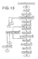
- Figure 12A shows the chemical analysis element 11 for measuring the concentration of a specific chemical component in the sample liquid.
- the chemical analysis element 11 comprises a square mount in which a reagent layer is provided and the reagent layer is exposed through a spotting hole 11a. Blood plasma is spotted onto the reagent layer through the spotting hole 11a.
- Figure 12B shows the chemical analysis elements 11' for measuring the ionic activity of a specific ion in the sample liquid.
- the chemical analysis element 11' is substantially the same in shape as the chemical analysis element 11 for measuring the concentration of a specific chemical component in the sample liquid and is provided with a pair of spotting holes 11c and 11d.
- the chemical analysis element 11' is provided with three pairs of ion selective electrodes 11e, 11f and 11g, each pair of ion selective electrodes being brought into electrical contact with the electrodes of the analyzer 21.
- the pairs of the ion selective electrodes 11e, 11f and 11g are provided with ion selective layers which are selective to Cl - , K + and Na + , respectively.
- a bar code for identifying terms of examination and the like is recorded on the back surface of the chemical analysis element 11(11').
- the blood plasma filtering unit 9 comprises a holder 1 which is mounted on the open end of a blood-gathering tube 7 placed in the sample holding portion 16 and a sucking means 2 which is connected to the holder 1 and supplies negative pressure for separating blood plasma from blood to the tube 7.
- the holder 1 comprises a body portion 1A and a lid member 1B which are formed of plastic.
- the body portion 1A comprises a plug portion 1a which is inserted into the tube 7, a filter holding portion 1b into which a filter 3 of a glass fiber or the like is inserted, and a flange portion 1c.
- the lid member 1B comprises a flange portion 1d, a cup 1e for holding blood plasma filtered by the filter 3 and a supply nozzle 1f which, supplies blood plasma from the filter 3 to the cup 1e.
- the lid member 1B is bonded to the body portion 1A by bonding the flange portions 1c and 1d together, for instance, by ultrasonic welding.
- the sucking means 2 comprises an arm 2a mounted on a shaft member 4 which is supported for rotation on a base 31.
- a suction pad portion 2b which sucks the lid member 1B of the holder 1 under suction is provided on the lower end of the arm 2a.
- the suction pad portion 2b is connected to a negative pressure supply portion 2c which is connected to a pump (not shown) and supplies a negative pressure to the suction pad portion 2b.
- the negative pressure supply portion 2c is provided with a pressure relief valve (not shown) for cutting the negative pressure from the pump.
- a liquid level sensor 2d which detects the liquid level of the blood plasma in the cup 1e and prevents the blood plasma from overflowing the cup 1e.
- a timing belt 5 ( Figure 1) is passed around the shaft member 4 and a drive pulley 6a of a drive motor 6 and the shaft member 4 is rotated back and forth in response to regular rotation and reverse rotation of the drive motor 6.
- the shaft member 4 is mounted for rotation on a support member 63 fixed to the base 31.
- a lead screw 64 is supported for rotation between the support member 63 and the base 31.
- a pulley 65 is fixed to the lower end portion of the lead screw 64.
- a timing belt 68 is passed around the pulley 65 and a drive pulley 67 of a drive motor 66.
- a fixed member 69 is fixed to the shaft member 4 and the lead screw 64 extends through a threaded through hole 69a in the fixed member 69 in mesh with the inner thread of the fixed member 69 so that the shaft member 4 is moved up and down in response to rotation of the lead screw 64.
- the holder 1 When blood plasma is to be separated from blood, the holder 1 is mounted on the blood-gathering tube 7 in the sample holding portion 16, and the arm 2a is rotated from an initial position shown by the solid line in Figure 1 to an operative position shown by the chained line in Figure 1 so that the suction pad portion 2b of the arm 2a is opposed to the holder 1. Then the arm 2a is moved downward to bring the suction pad portion 2b of the arm 2a into abutment against the lid member 1B of the holder 1.
- the suction pump (not shown) is operated to supply a negative pressure to a space between the suction pad portion 2b and the lid member 1B, whereby the whole blood in the blood-gathering tube 7 is sucked through the plug portion 1a and filtered by the filter 3.
- blood plasma passing through the filter 3 is supplied to the cup 1e through the supply nozzle 1f.
- the liquid level sensor 2d projects light onto the surface of the blood plasma supplied to the cup 1e and optically detects the reflected light from the surface of the blood plasma.
- the liquid level sensor 2d outputs a maximum signal when the liquid level of the plasma becomes substantially equal to the height of the cup 1e.
- the pressure relief valve is opened to terminate sucking of the blood. Thereafter, the arm 2a is moved upward and returned to the initial position shown by the solid line in Figure 1.
- the conveyor means 15 comprises a conveyor table 30 which has legs 30a at the front and rear ends thereof and is placed on the base 31, and the element supply section 12 is located at the middle of the conveyor table 30 and the spotting station 13 is located between the element supply section 12 and the incubator 14.
- the element supply section 12 is provided with an element guide 32 which holds the chemical analysis elements 11. Generally a stack of a plurality of virgin chemical analysis elements 11 are held in the element guide 32.
- the slide guide 32 is mounted on a recess of the conveyor table 30 so that the lowermost one of the chemical analysis elements 11 in the stack is positioned substantially flush with the upper surface of the conveyor table 30.
- An opening 32a which permits only a single chemical analysis element 11 to pass therethrough is formed in the front face of the element guide 32 at the lowermost portion thereof and an opening which permits insertion of a pusher (to be described later) is formed in the rear face of the element guide 32. Further a slit 32b which communicates with a slit 30b formed in the conveyor table 30 as will be described later is formed in the bottom of the element guide 32. A cartridge in which a stack of a plurality of chemical analysis elements 11 is stored may be set in the slide guide 32.
- An element pressing member 33 having a circular opening 33a is disposed at the spotting station 13.
- the element pressing member 33 is contained for up-and-down movement in a cover 34 fixed above the conveyor table 30.
- a glass plate 35 provided with a spotting opening 35a is fixed on the top of the cover 34.
- the spotting station 13 is provided with a bar-code reader 130 ( Figure 1) for reading the bar code on the chemical analysis element 11.
- the bar-code reader 130 is for identifying the terms of examination and the like and for detecting the position (upside down and/or inside out) of the chemical analysis element 11.
- the conveyance of the chemical analysis element 11 is effected by forward movement of a plate-like pusher 36 on the conveyor table 30. That is, a slit 30b extends in the longitudinal direction of the conveyor table 30 along the longitudinal axis thereof and the pusher 36 is mounted on the conveyor table 30 to be slidable along the slit 30b.
- a block 37 which is slidable along the slit 30b on the lower surface of the conveyor table 30 is fixed to the rear end portion of the pusher 36 by way of a connecting member extending through the slit 30b.
- An auxiliary plate 38 for pressing the pusher 36 against the upper surface of the conveyor table 30 is disposed above the conveyor table 30 behind the element supply section 12. The auxiliary plate 38 is held in a cover 39 to be slightly movable up and down.
- a slider 40 is mounted on the bottom of the block 37 and the slider 40 is supported for back and forth movement on a guide rod 41 extending along the conveyor table 30.
- An endless belt 44 passed around a pair of pulleys 42 and 43 disposed at the front and rear ends of the conveyor table 30 is fixed to the slider 40.
- the rear pulley 43 is driven by a conveyor motor 45 to slide the pusher 36 by way of the slider 40 and the block 37.
- the front end of the pusher 36 pushes the rear end face of the chemical analysis element 11 to insert the chemical analysis element 11 linearly into the incubator 14 from the spotting station 13.
- the conveyor motor 45 is controlled to convey the lowermost chemical analysis element 11 in the element guide 32 to the spotting station 13, to insert the chemical analysis element 11 spotted with sample liquid into the chemical analysis element receiving portion 55 in the incubator 14 and to convey the chemical analysis element 11 into the discarding hole 56 at the center of the incubator 14 after measurement.
- the incubator 14 comprises a disc-like rotary member 50 and an upper member 54 disposed on the rotary member 50.
- the rotary member 50 is provided with a tubular member 51 at the central portion of the lower surface thereof and the tubular member 51 is supported for rotation on a support member 53 by way of a bearing 52.
- the lower surface of the upper member 54 is flat and a plurality of (six in this particular embodiment) recesses are formed on the upper surface of the rotary member 50 at regular intervals in a circle, whereby a plurality of thin spaces which form the element receiving portions 55 are formed between the rotary member 50 and the upper member 54.
- the bottom surface of each element receiving portion 55 is flush with the upper surface of the conveyor table 30 and the outer peripheral surface of the rotary member 50 is positioned near the front end of the conveyor table 30.
- the inner hole of the tubular member 51 forms the discarding hole 56.
- the diameter of the discarding hole 56 is set so that the chemical analysis element 11 can pass through the discarding hole 56.
- the rotary member 50 is provided with an opening 50a which is formed at the center of the rotary member 50 to communicate with the discarding hole 56.
- the portion inside the element receiving portion 55 is flush with the bottom surface of the element receiving portion 55 and communicates with the opening 50a so that the chemical analysis element 11 in the element receiving portion 55 can be dropped into the discarding hole 56 by simply pushing the chemical analysis element 11 toward the center of the rotary member 50.
- a heating means (not shown) is provided on the upper member 54. By controlling the heating means, the chemical analysis element 11 in the element receiving portion 55 is held at a constant temperature. Further the upper member 54 is provided with a pressing member 57 which presses the mount of the chemical analysis element 11 from above and prevents evaporation of the sample liquid. A cover 58 is provided on the upper surface of the upper member 54. The incubator 14 is covered with upper and lower light-shielding covers 59 and 60.
- the heating means is controlled to hold the chemical analysis element 11 in the element receiving portion 55 at 37 ⁇ 0.2° C and when the ionic activity is to be measured, the heating means is controlled to hold the chemical analysis element 11 in the element receiving portion 55 at 30 ⁇ 0.1° C. That is, the chemical analysis elements 11 must be held at different temperatures according to the purpose of measurement.
- a pressing member 57' different from the pressing member 57 in shape is used for the chemical analysis element 11' for measuring the ionic activity and at the same the shape of the rotary member 50 is changed at the element receiving portion 55b for receiving the chemical analysis element 11' for measuring the ionic activity as will be described in detail later so that less heat is transmitted to the chemical analysis element 11' for measuring the ionic activity.
- An opening 55a for measuring light is formed in the center of the bottom surface of each element receiving portion 55 for receiving the chemical analysis element 11 for measuring the optical density thereof.
- the light measuring head 27 of the measuring means 18 disposed in the position shown in Figure 1 measures the amount of light reflected from the chemical analysis element 11 through the opening 55a.
- One 55b of the element receiving portions 55 is provided with three pairs of probe insertion holes 55c, 55d and 55f ( Figure 1) for measuring ionic activity (to be described later) and the chemical analysis element 11' for measuring the ionic activity is inserted into the element receiving portions 55b.
- the incubator 14 is rotated back and forth by a timing belt (not shown) passed around the tubular member 51 of the rotary member 50 and a drive pulley (not shown) of a drive motor. Rotation of the incubator 14 is controlled so that the light measuring head 27 positioned in a predetermined angular position of the incubator 14 is first opposed to a white reference plate and then opposed to a black reference plate. The light measuring head 27 measures the optical densities of the white and black reference plates and calibration is executed. Thereafter the chemical analysis elements 11 in the element receiving portions 55 are brought to the light measuring head 27 in sequence and the optical densities of the chemical analysis elements 11 are measured. Then the incubator 14 is reversed to return to the initial position.
- a chemical analysis element 11' is inserted into the element receiving portion 55b and the incubator 14 is rotated to bring the element receiving portion 55b to the analyzer 21. After measurement of the ionic activity, the incubator 14 is reversed to return to the initial position.
- a discarding box 70 for gathering chemical analysis elements 11 after measurement is disposed below the incubator 14.
- the inner space 71 of the discarding box 70 is positioned below the discarding hole 56 in the tubular member 51 of the incubator 14.
- the discarding box 70 is positioned so that the inner space 71 is shifted in one direction from the center of the incubator 14 due to the layout of other components.
- An inclined surface 72 is formed in a corner of the inner space 71.
- the inclined surface 72 is positioned below a tip removing portion 20 (to be described later) and nozzle tips 25 which are changed each time the sample liquid is changed are dropped onto the inclined surface 72.
- the inclined surface 72 is inclined downward (20 to 45°) toward the inner space 71 so that the nozzle tip 25 dropped onto the surface 72 falls down and are gathered toward the center of the inner space 71.
- a projection 73 erects from the bottom of the inner space 71 of the discarding box 70 in a positioned shifted from the center of the discarding hole 56 in the direction opposite to the direction in which the discarding box 70 is shifted from the center of the incubator 14.
- the tip of the projection 73 is like a ball or needle and the chemical analysis elements 11 dropped into the discarding box 70 through the discarding hole 56 change their directions of travel upon impact against the tip of the projection 73 so that the chemical analysis elements 11 are scatter over the wide area in the discarding box 70.
- the analyzer 21 for measuring the ionic activity is positioned below the rotary member 50 of the incubator 14.
- the basic structure of the analyzer 21 is disclosed, for instance, in United States Patent 4,257,862, Japanese Patent Publication Nos. 58(1983)-4981 and 6(1994)-82113 and Japanese Unexamined Patent Publication Nos. 58 (1983)-156848 and 58 (1983)-211648.
- the analyzer 21 is provided with three pairs of through holes 110, 111 and 112 and three pairs of potential measuring probes 113, 114 and 115 are supported for up-and-down movement in the through holes 110, 111 and 112. Since the probes 113, 114 and 114 are the same in arrangement, only the probes 113 will be described, hereinbelow.
- the probes 113 are fixed to an up-and-down member 121 which is moved up and down along a fixed member 120 erected from a base portion 150 and are in electrical contact with a measuring portion 122 of the analyzer 21.
- a holding member 123 which holds the chemical analysis element 11' together with the pressing member 57' is mounted on the up-and-down member 121.
- the pressing member 57' for the chemical analysis element 11' for measuring the ionic activity is concave toward the chemical analysis element 11' in order to reduce the contact area with the element 11' and not to be brought into contact with the sample liquid and/or the reference liquid.
- the up-and-down member 121 is urged downward in Figure 8 by a spring not shown.
- a drive motor 124 is disposed beside the up-and-down member 121 and a cam member 125 is mounted on the output shaft of the drive motor 125 to be opposed to an abutment portion 126 on one side of the up-and-down member 121.
- the cam member 125 moves from the position shown by the solid line to the position shown by the chained line to push upward the up-and-down member 121 by way of the abutment portion 126, whereby the probes 113 and the holding member 123 are moved upward.
- the cam member 125 is away from the abutment portion 126, the tips of the probes 113, 114 and 115 are retracted in the analyzer 21.
- the probes 113, 114 and 115 are projected from the surface of the analyzer 21 and are brought into electrical contact with the ion selective electrodes 11e, 11f and 11g of the chemical analysis element 11'.
- a chemical analysis element 11' spotted with blood plasma onto the spotting hole 11c and with the reference liquid onto the spotting hole 11d is inserted into the element receiving portion 55b and the rotary member 50 of the incubator 14 is rotated, after incubation for a predetermined time, to bring the receiving portion 55b to the analyzer 21. Then the probes 113, 114 and 115 are moved upward together with the holding member 123.
- the bottom wall of the element receiving portion 55b is formed with a cutaway portion which is shaped and sized to permit insertion of the holding member 123 and minimizes heat transmission from the rotary member 50 to the chemical analysis element 11' so that the chemical analysis element 11' is held at the temperature described above.
- the chemical analysis element 11 is held between the pressing member 57' and the holding member 123 and at the same time, the probes 113, 114 and 115 are respectively brought into contact with the ion selective electrodes 11e, 11f and 11g of the chemical analysis element 11'.
- the potential differences between the respective ion selective electrode pairs are measured, whereby the activities of Cl - , K + and Na + in the blood plasma are measured.
- the ionic activities thus measured are displayed on a display such as a liquid crystal panel and/or recorded on a paper.
- the sample holding portion 16 comprises a reference liquid tip holding portion 16a which holds a nozzle tip 25a for the reference liquid, an electrolyte sample tip holding portion 16b which holds a nozzle tip 25b for an electrolyte sample, a reference liquid holding tube 16c, a diluent tip holding portion 16d which holds a nozzle tip 25d for diluent, a diluent cup 16e, a mixing cup 16f, a blood-gathering cup holding portion 16g and a sample liquid tip holding portion 16h which holds a nozzle tip 25h for the sample liquid.
- the reference liquid tip holding portion 16a, the electrolyte sample tip holding portion 16b, the reference liquid holding tube 16c, the diluent tip holding portion 16d, the diluent cup 16e, the mixing cup 16f, the blood-gathering tube holding portion 16g and the sample liquid tip holding portion 16h are disposed along the path along which spotting nozzles 91a and 91b are moved in response to rotation of a spotting arm 88 of the spotting means 17 as will be described later.
- the sample holding portion 16 is a consumable good as a whole in this particular embodiment, and is replaceable.
- a flange member 83 is mounted for rotation by way of a bearing (not shown) on a support member 80 installed on the base 31.
- a pair of guide rods 84 are erected upward in parallel to each other from the upper surface of the flange member 83.
- the upper ends of the guide rods 84 are connected to a connecting member 85.
- a lead screw 86 extends between the connecting member 85 and the flange member 83 and is supported for rotation on the connecting member 85 and the flange member 83.
- the lower end portion of the lead screw 86 projects downward through the flange member 83 and a pulley 87 is fixed to the lower end of the lead screw 86.
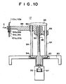
- a spotting arm 88 is supported on the guide rods 84 to be movable up and down along the guide rods 84 by way of a pair sleeves 89 which are fixed to the base end portion of the spotting arm 88 and slidably fitted on the guide rods 84.
- a through hole is formed in the base end portion of the spotting arm 88 and a nut member 90 is fixedly fitted in the through hole.
- the lead screw 86 extends through the base end portion of the spotting arm 88 and is in mesh with the nut member 90, whereby the spotting arm 88 is moved up and down in response to rotation of the lead screw 86.
- a pair of spotting nozzles 91a and 91b are mounted for up-and-down movement on the free end of the spotting arm 88 and urged downward respectively by a pair of springs 92a and 92b.
- the nozzle 91a is for a sample liquid and an electrolyte sample and the nozzle 91b is for a diluent and a reference liquid.
- Pipette-like nozzle tips 25a, 25b, 25d and 25h (will be represented by 25, hereinbelow) are removably mounted on the nozzles 91a and 91b.
- Virgin nozzle tips 25 are set in the sample holding portion 16 and are fitted on the spotting nozzles 91a and 91b in response to downward movement of the spotting arm 88. After use, the nozzle tips 25 are removed from the nozzles 91a and 91b by moving upward the spotting arm 88 with the upper end face of each tip 25 engaged with an engagement groove 20a of a tip removing portion 20 ( Figure 1) and are dropped into the discarding box 70 through an opening 20b.
- a timing belt 94 is passed around the flange member 83 and a drive pulley (not shown) on the output shaft of an arm rotating motor (not shown), and the arm rotating motor is rotated in regular and reverse directions to bring the nozzles 91a and 91b to predetermined positions. Further a timing belt 99 is passed around the pulley 87 on the lower end of the lead screw 86 and a drive pulley (not shown) on the output shaft of an arm lifting motor (not shown) and arm lifting motor is rotated in regular and reverse directions to rotate the lead screw 86, thereby moving up and down the spotting arm 88.
- Air passages 101a and 101b extend through the spotting nozzles 91a and 91b and air pipes 110a and 110b are connected respectively to the upper ends of the air passages 101a and 101b at their one ends.
- the other ends of the air pipes 110a and 110b are connected to a syringe 102 ( Figure 1) of a sucking mechanism 19.
- a solenoid valve (not shown) is provided in the sucking mechanism 19 and switching between the spotting nozzles 91a and 91b is effected by switching the solenoid valve.
- the spotting arm 88 When spotting a liquid onto a chemical analysis element 11, the spotting arm 88 is rotated to bring the nozzle tip 25 above the liquid and is moved downward to dip the nozzle tip 25 in to the liquid. Then the syringe 102 is operated to suck the liquid into the nozzle tip 25. Thereafter the spotting arm 88 is moved upward and is rotated to the spotting station 13 and is moved downward toward the chemical analysis element 11, where the syringe 102 is operated to discharge the liquid held in the nozzle tip 25 onto the chemical analysis element 11.
- the chemical analysis elements 11 are set in the chemical analysis element supply section 12 and the sample holding section 16 is set to the system as shown in Figure 1.
- the nozzle tip 25a for the reference liquid, the nozzle tip 25b for an electrolyte sample, the diluent, the nozzle tip 25d for the diluent, the blood-gathering tube 7 and the nozzle tip 25h for the sample liquid are held respectively in the reference liquid tip holding portion 16a, the electrolyte sample tip holding portion 16b, the diluent holding tube 16c, the diluent tip holding portion 16d, the blood-gathering tube holding portion 16g and the sample liquid tip holding portion 16h.
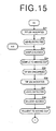
- step S1 the chemical analysis system is first initialized.
- step S2 the whole blood in the blood-gathering tube 7 is filtered to obtain blood plasma.
- step S2 The blood filtering procedure executed in step S2 will be described with reference to the flow chart shown in Figure 14, hereinbelow.
- step S21 stain of the liquid level sensor 2d is checked and the gain of the liquid level sensor 2d is set by setting a reference plate at the height of the cup 1e.
- step S21 Then the arm 2a is rotated to bring the suction pad portion 2b to a position where it is opposed to the holder 1 shown by the chained line in Figure 1, and the arm 2a is moved downward to bring the suction pad portion 2b into abutment against the lid member 1B of the holder 1.
- step S22 Then the pump (not shown) is operated to apply a negative pressure to the space between the lid member 1B and the suction pad portion 2b, whereby blood plasma passing through the filter 3 is supplied to the cup 1e through the supply nozzle 1f.
- step S23 At this time, it is possible to detect leakage and/or the hematcrit of the blood by checking the pressure in the pump.
- step S24 In place of detecting the liquid level by the liquid level sensor 2d, the pump may be stopped after a predetermined time. Thereafter the pressure relief valve of the negative pressure supply portion 2c is opened to cut supply of the negative pressure from the pump (step S25) and the arm 2a is moved upward to move the suction pad portion 2b away from the lid member 1B and returned to the initial position shown by the solid line in Figure 1.
- a chemical analysis element 11 is conveyed to the spotting station 13 from the element supply section 12 by the conveyor means 15. Then bar-code reader 130 reads the bar code on the chemical analysis element 11 to detect the terms of examination and the like.
- step S3 When the term of examination read is measurement of the ionic activity, the procedure proceeds to B, and when the term of examination read is measurement of the optical density after dilution, the procedure proceeds to A1.
- the spotting arm 88 is rotated to bring the spotting nozzle 91a to the sample holding portion 16 and the nozzle tip 25h for the sample liquid is mounted on the nozzle 91a.
- step S4 Then the liquid level of the sample liquid (blood plasma) in the cup 1e is detected to know the liquid level and to confirm whether a necessary amount of blood plasma exists in the cup 1e.
- step S5 The spotting arm 88 is thereafter moved downward and the sample liquid in the cup 1e is sucked into the nozzle tip 25h (step S6), and the spotting arm 88 is driven to bring the nozzle tip 25h to the spotting station 13 and the sample liquid is spotted onto the chemical analysis element 11 through the spotting hole 11a (step S7). At this time, it is possible to detect clogging of the tip 25h by detecting the change in pressure and comparing the change with a reference value.
- step S8 the chemical analysis element 11 spotted with the sample liquid is inserted into the incubator 14 which is held at 37 ⁇ 0.2° C.
- step S13 steps S6 to S8 are repeated.
- the term of examination read is measurement of the ionic activity
- the procedure proceeds to B after the nozzle tip 25h is discarded in step S14, and when the term of examination read is measurement of the optical density after dilution, the procedure proceeds to A2.
- step S9 After the measurement, the conveyor means 15 pushes the chemical analysis element 11 toward the center of the incubator 14 and drops the same into the discarding hole 56.
- step S10 Thereafter the result of the measurement is output in step S11, and the nozzle tip 25h is removed from the nozzle 91a at the tip removing portion 20 and is discarded in step S12.
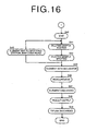
- step S31 the spotting arm 88 is rotated to bring the spotting nozzle 91a to the sample holding portion 16 and the nozzle tip 25h for the sample liquid is mounted on the nozzle 91a. Then the liquid level of the sample liquid (blood plasma) in the cup 1e is detected to know the liquid level and to confirm whether a necessary amount of blood plasma exists in the cup 1e.
- step S32 The spotting arm 88 is thereafter moved downward and the sample liquid in the cup 1e is sucked into the nozzle tip 25h (step S33). At this time, it is possible to detect clogging of the tip 25h by detecting the change in pressure and comparing the change with a reference value.
- step S34 the sample liquid in the nozzle tip 25h is discharged into the mixing cup 16f.
- the nozzle tip 25h is thereafter removed from the nozzle 91a at the tip removing portion 20 and is discarded in step S35.
- the spotting arm 88 is rotated to bring the spotting nozzle 91b to the sample holding portion 16 and the nozzle tip 25d for the diluent is mounted on the nozzle 91b.
- step S36 the liquid level of the diluent in the diluent cup 16e is detected to know the liquid level and to confirm whether a necessary amount of diluent exists in the cup 16e.
- step S37 The spotting arm 88 is thereafter moved downward and the diluent in the cup 16e is sucked into the nozzle tip 25d.
- step S38 At this time, it is possible to detect clogging of the tip 25d by detecting the change in pressure and comparing the change with a reference value.
- step S39 the diluent in the nozzle tip 25d is discharged into the mixing cup 16f. Thereafter, the nozzle tip 25d is dipped into the mixed liquid and sucking and discharging are alternately repeated to stir the mixture.
- step S40 After the stir, the diluted sample liquid is sucked into the tip 25d and the spotting arm 88 is driven to bring the nozzle tip 25d to the spotting station 13 and the diluted sample liquid is spotted onto the chemical analysis element 11 through the spotting hole 11a (steps S41 and S42). At this time, it is possible to detect clogging of the tip 25d by detecting the change in pressure and comparing the change with a reference value.
- step S43 When a plurality of chemical analysis elements 11 are continuously processed, other chemical analysis elements 11 are conveyed to the spotting station 13 one by one and the bar codes on the elements are read (step S43) and steps S41 and S42 are repeated.
- steps S45 to S49 the chemical analysis element 11 spotted with the diluted sample liquid is inserted into the incubator 14, the rotary member 50 is rotated to bring the chemical analysis elements 11 in the element receiving portions 55 to the light measuring head 27 in sequence, the reflective optical density of each chemical analysis element 11 is measured by the light measuring head, the conveyor means 15 pushes the chemical analysis element 11 toward the center of the incubator 14 and drops the same into the discarding hole 56, the result of the measurement is output, and the nozzle tip 25d is removed from the nozzle 91a and is discarded.
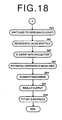
- the chemical analysis element conveyed in step S3 in Figure 13 is a chemical analysis element 11' for measurement of the ionic activity.
- the spotting arm 88 is rotated to bring the spotting nozzle 91a to the sample holding portion 16 and the nozzle tip 25b for the electrolyte sample is mounted on the nozzle 91a.
- step S51 the liquid level of the sample liquid (blood plasma) in the cup 1e is detected to know the liquid level and to confirm whether a necessary amount of blood plasma exists in the cup 1e.
- step S52 The spotting arm 88 is thereafter moved downward and the sample liquid in the cup 1e is sucked into the nozzle tip 25b (step S53). At this time, it is possible to detect clogging of the tip 25b by detecting the change in pressure and comparing the change with a reference value.
- step S54 the solenoid valve in the sucking mechanism 19 is switched to switch the flow passage of the pressure to the spotting nozzle 91b. Then the spotting arm 88 is rotated to bring the spotting nozzle 91b to the sample holding portion 16 and the nozzle tip 25a for the reference liquid is mounted on the nozzle 91b. (step S55) Then the liquid level of the reference liquid in the holding tube 16c is detected to know the liquid level and to confirm whether a necessary amount of reference liquid exists in the holding tube 16c. (step S56) The spotting arm 88 is thereafter moved downward and the reference liquid in the holding tube 16c is sucked into the nozzle tip 25a (step S57). At this time, it is possible to detect clogging of the tip 25a by detecting the change in pressure and comparing the change with a reference value.
- step S58 the solenoid valve in the sucking mechanism 19 is switched to switch the flow passage of the pressure to the spotting nozzle 91a. Then the spotting arm 88 is rotated to bring the spotting nozzle 91a to the spotting station 13 and the sample liquid in the nozzle tip 25b is spotted onto the spotting hole 11c of the chemical analysis element 11'. (step S59) Then in step S60, the solenoid valve in the sucking mechanism 19 is switched to switch the flow passage of the pressure to the spotting nozzle 91b and in step S61, the reference liquid in the nozzle top 25a is spotted onto the spotting hole 11d of the chemical analysis element 11'.
- step S62 the chemical analysis element 11' spotted with the sample liquid and the reference liquid is inserted into the element receiving portion 55b of the incubator 14 and is held at 30 ⁇ 1° C.
- the rotary member 50 is rotated to bring the chemical analysis element 11' in the element receiving portion 55b to the analyzer 21 and the ionic activity is measured by the analyzer 21.
- step S63 After the measurement, the conveyor means 15 pushes the chemical analysis element 11' toward the center of the incubator 14 and drops the same into the discarding hole 56.
- step S64 Thereafter the result of the measurement is output in step S65, and the nozzle tips 25a and 25b are removed from the nozzles 91a and 91b at the tip removing portion 20 and are discarded in step S66.
- the chemical analysis elements 11 inserted into the element receiving portions 55 for measurement of the optical density are held at a constant temperature suitable for the measurement and the chemical analysis element 11' inserted into the element receiving portion 55b for measurement of the ionic activity is held at a constant temperature suitable for the measurement, measurement of the optical density and measurement of the ionic activity both can be effected efficiently in a single chemical analysis system.
- the number of the element receiving portions 55 in the incubator 14 may be changed as desired and the blood filtering unit 9 may be placed in any position.
Landscapes
- Physics & Mathematics (AREA)
- Health & Medical Sciences (AREA)
- Life Sciences & Earth Sciences (AREA)
- Chemical & Material Sciences (AREA)
- Analytical Chemistry (AREA)
- Biochemistry (AREA)
- General Health & Medical Sciences (AREA)
- General Physics & Mathematics (AREA)
- Immunology (AREA)
- Pathology (AREA)
- Engineering & Computer Science (AREA)
- Quality & Reliability (AREA)
- Automatic Analysis And Handling Materials Therefor (AREA)
- Investigating Or Analysing Biological Materials (AREA)
- Investigating Or Analysing Materials By The Use Of Chemical Reactions (AREA)
Description
- This invention relates to a chemical analysis system according to the preamble of
claim 1. A system of this type is know from EP-A-0 397 256. - There has been put into practice a dry ("dry-to-the-touch") chemical analysis element with which a specific chemical component or a solid component contained in a sample liquid can be quantitatively analyzed by only spotting a droplet of the sample liquid onto the element.
- When quantitatively analyzing the chemical components or the like contained in a sample liquid using such a dry chemical analysis element, a droplet of the sample liquid is spotted onto the element and is held at a constant temperature for a predetermined time (incubation) in an incubator so that coloring reaction occurs, and the optical density of the color formed by the coloring reaction is optically measured. That is, measuring light containing a wavelength which is pre-selected according to the combination of the component to be analyzed and the reagent contained in the reagent layer of the element is projected onto the element and the optical density of the element is measured. Then the concentration of the component to be analyzed is determined on the basis of the optical density using a standard curve which represents the relation between the concentration of the biochemical component and the optical density.
- In the chemical analysis system, the chemical analysis elements are transferred to the incubator one by one in sequence and taken out from the incubator to be discarded after measurement of the concentration. For example, as disclosed in Japanese Unexamined Patent Publication No. 61(1986)-26864, United States Patent No. 4,296,069, the chemical analysis elements are carried in a disc-like incubator from the outer side of the incubator and taken out from the outer side of the same by ejecting the chemical analysis element from the inner side of the same or drawing out the chemical analysis element from the outer side of the incubator.
- Further there has been known a chemical analysis system in which the incubator is rotatable about its axis and has a plurality of chemical analysis element receiving portions arranged in a circle about the axis of rotation of the incubator and each chemical analysis element is inserted into one of the receiving portions by a conveyor means which conveys the chemical analysis element linearly toward the axis of rotation of the incubator and is pushed further toward the axis of rotation of the incubator by the conveyor means, after measurement of the concentration, into a discarding hole which opens at the center of the incubator. (See Japanese Unexamined Patent Publication No. 6(1994)-66818.)
- Further there has been known an ionic activity measuring system for measuring an activity of a specific ion contained in a sample liquid as disclosed, for instance, in United States Patent No. 4,257,862, Japanese Patent Publication No. 58(1983)-4981, Japanese Unexamined Patent Publication Nos. 58(1983)-156848 and 58(1983)-211648 and Japanese Patent Publication No. 6(1994)-82113. A chemical analysis element used in such an ionic activity measuring system comprises a pair of ion selective electrodes and a porous bridge which connects the ion selective electrodes. When a reference liquid containing therein the specific ion whose ionic activity is known is spotted onto one of the ion selective electrodes and a sample liquid containing therein the specific ion whose ionic activity is not known is spotted onto the other ion selective electrode, the reference liquid and the sample liquid come to electrically contact with each other through the porous bridge and a potential difference is produced between the ion selective electrodes according to the difference in the ionic activity between the specific ions contained in the sample liquid and the reference liquid. The ionic activity of the specific ion in the sample liquid can be determined according to the potential difference on the basis of a standard curve which has been obtained in advance according to Nernst equation.
- It is preferred that the ionic activity measuring system for measuring the ionic activity of a specific ion in a sample liquid using such a chemical analysis element be in the form of an analyzer which is provided with both function to spotting the sample liquid and the reference liquid onto the ion selective electrodes and function to measure the potential difference. In such an analyzer, the chemical analysis element spotted with the sample liquid and the reference liquid is transferred to a potential difference measuring section, where potential measurement probes are brought into contact with the ion selective electrodes to measure the potential difference between the electrodes.
- When the sample liquid is to be analyzed, it is sometimes necessary to determine both the concentration of a specific chemical component and the ionic activity of a specific ion. However, in conventional chemical analysis systems, the system for measuring the concentration of a chemical component and the system for measuring the ionic activity of an ion are separate from each other and accordingly, measurement of both the concentration of the chemical component and the ionic activity cannot be efficiently effected. Further the incubation temperature when the concentration of a chemical component is to be determined is sometimes different from that when the activity of an ion is to be determined and accordingly determination of the concentration of the chemical component and determination of the ionic activity must be effected with separate systems, which largely deteriorates efficiency of measurements.
- EP-A-0 397 256 discloses a chemical analysis system. In this prior art system, the two different types of chemical analysis elements have the same temperature.
- US-A-4,857,272 discloses a chemical analysis system in which a first incubator maintains a first group of elements at a first temperature, while a second incubator maintains a further element at a second temperature.
- In view of the foregoing observations and description, the primary object of the present invention is to provide a chemical analysis system in which measurement of the concentration of a specific chemical component and the activity of a specific ion can be both effected efficiently.
- In accordance with the present invention, there is provided a chemical analysis system comprising the features of
claim 1. - The chemical analysis system of the invention is useful when the chemical analysis element for measuring the concentration of a specific component contained in the sample liquid and the chemical analysis element for measuring the activity of a specific ion contained in the sample liquid should be incubated at different temperatures.
- In the chemical analysis systems in accordance with the present invention, it is preferred that there is further provided with a chemical analysis element supply section which stores both the first and second chemical analysis elements, and a conveyor means for conveying the chemical analysis element in the chemical analysis element supply section to the incubator.
- Further it is preferred that each chemical analysis element is provided with a bar code and the chemical analysis system is further provided with a detecting means which detects the position of the chemical analysis element in which the chemical analysis element is conveyed by reading the bar code.
- In the case of the chemical analysis element for measuring the ionic activity, the ionic activity cannot be accurately measured if the spotting order of the sample liquid and the reference liquid is reversed. By detecting the position of the chemical analysis element in which the chemical analysis element is conveyed, it is possible to give the alarm to the operator when the chemical analysis element is conveyed in a wrong position. The bar code may be used for identifying the term of examination and the like.
- Further it is preferred that there is further provided a diluting unit which includes a sample liquid container and dilutes the sample liquid in the container with diluent.
- In the chemical analysis systems of the present invention, since both the concentration measuring means and the ionic activity measuring means are provided and the chemical analysis element for measuring the concentration of the specific component and the chemical analysis element for measuring the ionic activity are incubated in the same incubator, both the measurements can be effected efficiently.
- Further when a chemical analysis element supply section which stores both the first and second chemical analysis elements and a conveyor means for conveying the chemical analysis element in the chemical analysis element supply section to the incubator are provided, both the first and second chemical analysis elements can be conveyed to the incubator by a single conveyor means, whereby the structure of the system can be simplified.
- Further when each chemical analysis element is provided with a bar code and the chemical analysis system is further provided with a detecting means which detects the position of the chemical analysis element in which the chemical analysis element is conveyed by reading the bar code, mistake in measurement of the ionic activity can be avoided.
- Further when a diluting unit which dilutes the sample liquid is provided, a sample liquid which is desired to be diluted before analysis can be quickly analyzed.
-
- Figure 1 is a schematic plan view of an important part of the chemical analysis system in accordance with an embodiment of the present invention,
- Figure 2 is a schematic front view showing the blood filtering unit,
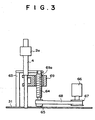
- Figure 3 is a schematic side view showing the blood filtering unit,
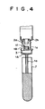
- Figure 4 is a fragmentary front view of the blood filtering unit in operation,
- Figure 5 is a fragmentary cross-sectional view showing the conveyor means,
- Figure 6 is a fragmentary cross-sectional showing the incubator,
- Figure 7 is a fragmentary plan view showing the analyzer,
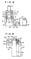
- Figure 8 is a cross-sectional view taken along line I-I in Figure 7,
- Figure 9 is a view showing the sample holding portion,
- Figure 10 is a cross-sectional view of the spotting means,
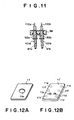
- Figure 11 is a fragmentary enlarged view as seen in the direction of arrow A in Figure 11,
- Figure 12A is a perspective view of the chemical analysis element for measuring the optical density,
- Figure 12B is a perspective view of the chemical analysis element for measuring the ionic activity,
- Figure 13 is a flow chart for illustrating the operation of the chemical analysis system,
- Figure 14 is a flow chart for illustrating the blood filtering processing,
- Figures 15 and 16 show a flow chart for illustrating the dilution processing, and
- Figures 17 and 18 show a flow chart for illustrating the ionic activity measuring processing.
- In Figure 1, a
chemical analysis system 10 in accordance with an embodiment of the present invention comprises a bloodplasma filtering unit 9 which separates blood plasma from blood, a chemical analysiselement supply section 12 in which a plurality of virginchemical analysis elements 11 for measuring the concentration of a specific component in blood plasma and/or virgin chemical analysis elements 11' for measuring the ionic activity of a specific ion in blood plasma (both thechemical analysis elements 11 and 11' will be sometimes represented by 11, hereinbelow) are contained, aspotting station 13 at which a sample liquid (blood plasma in this particular embodiment but may be the whole blood, blood serum, urine or the like) and/or a reference liquid or a diluent liquid in asample holding portion 16 is spotted onto thechemical analysis element 11 as will be described in detail later, and anincubator 14 which receives therein thechemical analysis elements 11 and holds thechemical analysis elements 11 at a constant temperature for a predetermined time. A conveyor means 15 conveys thechemical analysis elements 11 one by one from theelement supply section 12 to thespotting station 13. At thespotting station 13, a spotting means 17 spots a predetermined amount of the sample liquid (blood plasma) and/or the reference liquid or the diluent liquid onto thechemical analysis element 11 as will be described in detail later. Then thechemical analysis element 11 spotted with the sample liquid is inserted into a chemical analysiselement receiving portion 55 in theincubator 14 by the conveyor means 15. After thechemical analysis element 11 is incubated for a predetermined time, the optical density of thechemical analysis element 11 is measured by alight measuring head 27 of ameasuring means 18 or the ionic activity of the sample liquid spotted onto the chemical analysis element 11' is measured by ananalyzer 21. After the measurement, thechemical analysis element 11 is dropped into a discardinghole 56 at the center of theincubator 14 by the conveyor means 15. - Figure 12A shows the
chemical analysis element 11 for measuring the concentration of a specific chemical component in the sample liquid. As shown in Figure 12A, thechemical analysis element 11 comprises a square mount in which a reagent layer is provided and the reagent layer is exposed through a spotting hole 11a. Blood plasma is spotted onto the reagent layer through the spotting hole 11a. Figure 12B shows the chemical analysis elements 11' for measuring the ionic activity of a specific ion in the sample liquid. As shown in Figure 12B, the chemical analysis element 11' is substantially the same in shape as thechemical analysis element 11 for measuring the concentration of a specific chemical component in the sample liquid and is provided with a pair of spottingholes hole 11c and a reference liquid is spotted onto thespotting hole 11d. Further the chemical analysis element 11' is provided with three pairs of ionselective electrodes analyzer 21. The pairs of the ionselective electrodes - As shown in Figures 2 and 3, the blood
plasma filtering unit 9 comprises aholder 1 which is mounted on the open end of a blood-gatheringtube 7 placed in thesample holding portion 16 and a suckingmeans 2 which is connected to theholder 1 and supplies negative pressure for separating blood plasma from blood to thetube 7. Theholder 1 comprises abody portion 1A and a lid member 1B which are formed of plastic. Thebody portion 1A comprises aplug portion 1a which is inserted into thetube 7, a filter holding portion 1b into which afilter 3 of a glass fiber or the like is inserted, and aflange portion 1c. The lid member 1B comprises aflange portion 1d, acup 1e for holding blood plasma filtered by thefilter 3 and asupply nozzle 1f which, supplies blood plasma from thefilter 3 to thecup 1e. The lid member 1B is bonded to thebody portion 1A by bonding theflange portions - The sucking means 2 comprises an
arm 2a mounted on ashaft member 4 which is supported for rotation on abase 31. Asuction pad portion 2b which sucks the lid member 1B of theholder 1 under suction is provided on the lower end of thearm 2a. Thesuction pad portion 2b is connected to a negativepressure supply portion 2c which is connected to a pump (not shown) and supplies a negative pressure to thesuction pad portion 2b. The negativepressure supply portion 2c is provided with a pressure relief valve (not shown) for cutting the negative pressure from the pump. In thesuction pad portion 2b is disposed aliquid level sensor 2d which detects the liquid level of the blood plasma in thecup 1e and prevents the blood plasma from overflowing thecup 1e. A timing belt 5 (Figure 1) is passed around theshaft member 4 and adrive pulley 6a of a drive motor 6 and theshaft member 4 is rotated back and forth in response to regular rotation and reverse rotation of the drive motor 6. - Further as shown in Figure 3, the
shaft member 4 is mounted for rotation on asupport member 63 fixed to thebase 31. Alead screw 64 is supported for rotation between thesupport member 63 and thebase 31. Apulley 65 is fixed to the lower end portion of thelead screw 64. Atiming belt 68 is passed around thepulley 65 and adrive pulley 67 of adrive motor 66. A fixed member 69 is fixed to theshaft member 4 and thelead screw 64 extends through a threaded throughhole 69a in the fixed member 69 in mesh with the inner thread of the fixed member 69 so that theshaft member 4 is moved up and down in response to rotation of thelead screw 64. - When blood plasma is to be separated from blood, the
holder 1 is mounted on the blood-gatheringtube 7 in thesample holding portion 16, and thearm 2a is rotated from an initial position shown by the solid line in Figure 1 to an operative position shown by the chained line in Figure 1 so that thesuction pad portion 2b of thearm 2a is opposed to theholder 1. Then thearm 2a is moved downward to bring thesuction pad portion 2b of thearm 2a into abutment against the lid member 1B of theholder 1. Thereafter the suction pump (not shown) is operated to supply a negative pressure to a space between thesuction pad portion 2b and the lid member 1B, whereby the whole blood in the blood-gatheringtube 7 is sucked through theplug portion 1a and filtered by thefilter 3. Thus blood plasma passing through thefilter 3 is supplied to thecup 1e through thesupply nozzle 1f. - The
liquid level sensor 2d projects light onto the surface of the blood plasma supplied to thecup 1e and optically detects the reflected light from the surface of the blood plasma. Theliquid level sensor 2d outputs a maximum signal when the liquid level of the plasma becomes substantially equal to the height of thecup 1e. When theliquid level sensor 2d outputs a maximum signal, the pressure relief valve is opened to terminate sucking of the blood. Thereafter, thearm 2a is moved upward and returned to the initial position shown by the solid line in Figure 1. - As shown in Figure 5, the conveyor means 15 comprises a conveyor table 30 which has
legs 30a at the front and rear ends thereof and is placed on thebase 31, and theelement supply section 12 is located at the middle of the conveyor table 30 and the spottingstation 13 is located between theelement supply section 12 and theincubator 14. Theelement supply section 12 is provided with anelement guide 32 which holds thechemical analysis elements 11. Generally a stack of a plurality of virginchemical analysis elements 11 are held in theelement guide 32. Theslide guide 32 is mounted on a recess of the conveyor table 30 so that the lowermost one of thechemical analysis elements 11 in the stack is positioned substantially flush with the upper surface of the conveyor table 30. Anopening 32a which permits only a singlechemical analysis element 11 to pass therethrough is formed in the front face of theelement guide 32 at the lowermost portion thereof and an opening which permits insertion of a pusher (to be described later) is formed in the rear face of theelement guide 32. Further aslit 32b which communicates with aslit 30b formed in the conveyor table 30 as will be described later is formed in the bottom of theelement guide 32. A cartridge in which a stack of a plurality ofchemical analysis elements 11 is stored may be set in theslide guide 32. - An
element pressing member 33 having acircular opening 33a is disposed at the spottingstation 13. Theelement pressing member 33 is contained for up-and-down movement in acover 34 fixed above the conveyor table 30. Aglass plate 35 provided with aspotting opening 35a is fixed on the top of thecover 34. Further the spottingstation 13 is provided with a bar-code reader 130 (Figure 1) for reading the bar code on thechemical analysis element 11. The bar-code reader 130 is for identifying the terms of examination and the like and for detecting the position (upside down and/or inside out) of thechemical analysis element 11. - The conveyance of the
chemical analysis element 11 is effected by forward movement of a plate-like pusher 36 on the conveyor table 30. That is, aslit 30b extends in the longitudinal direction of the conveyor table 30 along the longitudinal axis thereof and thepusher 36 is mounted on the conveyor table 30 to be slidable along theslit 30b. Ablock 37 which is slidable along theslit 30b on the lower surface of the conveyor table 30 is fixed to the rear end portion of thepusher 36 by way of a connecting member extending through theslit 30b. Anauxiliary plate 38 for pressing thepusher 36 against the upper surface of the conveyor table 30 is disposed above the conveyor table 30 behind theelement supply section 12. Theauxiliary plate 38 is held in acover 39 to be slightly movable up and down. - A
slider 40 is mounted on the bottom of theblock 37 and theslider 40 is supported for back and forth movement on aguide rod 41 extending along the conveyor table 30. Anendless belt 44 passed around a pair ofpulleys slider 40. Therear pulley 43 is driven by aconveyor motor 45 to slide thepusher 36 by way of theslider 40 and theblock 37. The front end of thepusher 36 pushes the rear end face of thechemical analysis element 11 to insert thechemical analysis element 11 linearly into theincubator 14 from the spottingstation 13. - The
conveyor motor 45 is controlled to convey the lowermostchemical analysis element 11 in theelement guide 32 to the spottingstation 13, to insert thechemical analysis element 11 spotted with sample liquid into the chemical analysiselement receiving portion 55 in theincubator 14 and to convey thechemical analysis element 11 into the discardinghole 56 at the center of theincubator 14 after measurement. - As shown in Figure 6, the
incubator 14 comprises a disc-like rotary member 50 and anupper member 54 disposed on therotary member 50. Therotary member 50 is provided with atubular member 51 at the central portion of the lower surface thereof and thetubular member 51 is supported for rotation on asupport member 53 by way of abearing 52. The lower surface of theupper member 54 is flat and a plurality of (six in this particular embodiment) recesses are formed on the upper surface of therotary member 50 at regular intervals in a circle, whereby a plurality of thin spaces which form theelement receiving portions 55 are formed between therotary member 50 and theupper member 54. The bottom surface of eachelement receiving portion 55 is flush with the upper surface of the conveyor table 30 and the outer peripheral surface of therotary member 50 is positioned near the front end of the conveyor table 30. - The inner hole of the
tubular member 51 forms the discardinghole 56. The diameter of the discardinghole 56 is set so that thechemical analysis element 11 can pass through the discardinghole 56. Therotary member 50 is provided with anopening 50a which is formed at the center of therotary member 50 to communicate with the discardinghole 56. The portion inside theelement receiving portion 55 is flush with the bottom surface of theelement receiving portion 55 and communicates with theopening 50a so that thechemical analysis element 11 in theelement receiving portion 55 can be dropped into the discardinghole 56 by simply pushing thechemical analysis element 11 toward the center of therotary member 50. - A heating means (not shown) is provided on the
upper member 54. By controlling the heating means, thechemical analysis element 11 in theelement receiving portion 55 is held at a constant temperature. Further theupper member 54 is provided with a pressingmember 57 which presses the mount of thechemical analysis element 11 from above and prevents evaporation of the sample liquid. Acover 58 is provided on the upper surface of theupper member 54. Theincubator 14 is covered with upper and lower light-shielding covers 59 and 60. When the degree of coloring (optical density) of thechemical analysis element 11 is to be measured, the heating means is controlled to hold thechemical analysis element 11 in theelement receiving portion 55 at 37±0.2° C and when the ionic activity is to be measured, the heating means is controlled to hold thechemical analysis element 11 in theelement receiving portion 55 at 30±0.1° C. That is, thechemical analysis elements 11 must be held at different temperatures according to the purpose of measurement. However, since only a single heating means is provided, a pressing member 57' different from the pressingmember 57 in shape is used for the chemical analysis element 11' for measuring the ionic activity and at the same the shape of therotary member 50 is changed at the element receiving portion 55b for receiving the chemical analysis element 11' for measuring the ionic activity as will be described in detail later so that less heat is transmitted to the chemical analysis element 11' for measuring the ionic activity. - An
opening 55a for measuring light is formed in the center of the bottom surface of eachelement receiving portion 55 for receiving thechemical analysis element 11 for measuring the optical density thereof. Thelight measuring head 27 of the measuring means 18 disposed in the position shown in Figure 1 measures the amount of light reflected from thechemical analysis element 11 through theopening 55a. One 55b of theelement receiving portions 55 is provided with three pairs ofprobe insertion holes - The
incubator 14 is rotated back and forth by a timing belt (not shown) passed around thetubular member 51 of therotary member 50 and a drive pulley (not shown) of a drive motor. Rotation of theincubator 14 is controlled so that thelight measuring head 27 positioned in a predetermined angular position of theincubator 14 is first opposed to a white reference plate and then opposed to a black reference plate. Thelight measuring head 27 measures the optical densities of the white and black reference plates and calibration is executed. Thereafter thechemical analysis elements 11 in theelement receiving portions 55 are brought to thelight measuring head 27 in sequence and the optical densities of thechemical analysis elements 11 are measured. Then theincubator 14 is reversed to return to the initial position. When the ionic activity is to be measured, a chemical analysis element 11' is inserted into the element receiving portion 55b and theincubator 14 is rotated to bring the element receiving portion 55b to theanalyzer 21. After measurement of the ionic activity, theincubator 14 is reversed to return to the initial position. - A discarding
box 70 for gatheringchemical analysis elements 11 after measurement is disposed below theincubator 14. Theinner space 71 of the discardingbox 70 is positioned below the discardinghole 56 in thetubular member 51 of theincubator 14. The discardingbox 70 is positioned so that theinner space 71 is shifted in one direction from the center of theincubator 14 due to the layout of other components. Aninclined surface 72 is formed in a corner of theinner space 71. Theinclined surface 72 is positioned below a tip removing portion 20 (to be described later) and nozzle tips 25 which are changed each time the sample liquid is changed are dropped onto theinclined surface 72. Theinclined surface 72 is inclined downward (20 to 45°) toward theinner space 71 so that the nozzle tip 25 dropped onto thesurface 72 falls down and are gathered toward the center of theinner space 71. - A
projection 73 erects from the bottom of theinner space 71 of the discardingbox 70 in a positioned shifted from the center of the discardinghole 56 in the direction opposite to the direction in which the discardingbox 70 is shifted from the center of theincubator 14. The tip of theprojection 73 is like a ball or needle and thechemical analysis elements 11 dropped into the discardingbox 70 through the discardinghole 56 change their directions of travel upon impact against the tip of theprojection 73 so that thechemical analysis elements 11 are scatter over the wide area in the discardingbox 70. - As shown in Figure 1, the
analyzer 21 for measuring the ionic activity is positioned below therotary member 50 of theincubator 14. The basic structure of theanalyzer 21 is disclosed, for instance, in United States Patent 4,257,862, Japanese Patent Publication Nos. 58(1983)-4981 and 6(1994)-82113 and Japanese Unexamined Patent Publication Nos. 58 (1983)-156848 and 58 (1983)-211648. As shown in Figures 7 and 8, theanalyzer 21 is provided with three pairs of throughholes holes probes probes 113 will be described, hereinbelow. - As shown in Figure 8, the
probes 113 are fixed to an up-and-down member 121 which is moved up and down along a fixedmember 120 erected from abase portion 150 and are in electrical contact with a measuring portion 122 of theanalyzer 21. A holdingmember 123 which holds the chemical analysis element 11' together with the pressing member 57' is mounted on the up-and-down member 121. The pressing member 57' for the chemical analysis element 11' for measuring the ionic activity is concave toward the chemical analysis element 11' in order to reduce the contact area with the element 11' and not to be brought into contact with the sample liquid and/or the reference liquid. The up-and-down member 121 is urged downward in Figure 8 by a spring not shown. Adrive motor 124 is disposed beside the up-and-down member 121 and a cam member 125 is mounted on the output shaft of the drive motor 125 to be opposed to anabutment portion 126 on one side of the up-and-down member 121. In response to rotation of thedrive motor 124, the cam member 125 moves from the position shown by the solid line to the position shown by the chained line to push upward the up-and-down member 121 by way of theabutment portion 126, whereby theprobes 113 and the holdingmember 123 are moved upward. When the cam member 125 is away from theabutment portion 126, the tips of theprobes analyzer 21. However when the up-and-down member 121 is moved upward, theprobes analyzer 21 and are brought into electrical contact with the ionselective electrodes - A chemical analysis element 11' spotted with blood plasma onto the spotting
hole 11c and with the reference liquid onto thespotting hole 11d is inserted into the element receiving portion 55b and therotary member 50 of theincubator 14 is rotated, after incubation for a predetermined time, to bring the receiving portion 55b to theanalyzer 21. Then theprobes member 123. The bottom wall of the element receiving portion 55b is formed with a cutaway portion which is shaped and sized to permit insertion of the holdingmember 123 and minimizes heat transmission from therotary member 50 to the chemical analysis element 11' so that the chemical analysis element 11' is held at the temperature described above. Thechemical analysis element 11 is held between the pressing member 57' and the holdingmember 123 and at the same time, theprobes selective electrodes - As shown in Figure 9, the
sample holding portion 16 comprises a reference liquidtip holding portion 16a which holds anozzle tip 25a for the reference liquid, an electrolyte sampletip holding portion 16b which holds anozzle tip 25b for an electrolyte sample, a referenceliquid holding tube 16c, a diluenttip holding portion 16d which holds anozzle tip 25d for diluent, a diluent cup 16e, a mixingcup 16f, a blood-gatheringcup holding portion 16g and a sample liquidtip holding portion 16h which holds anozzle tip 25h for the sample liquid. The reference liquidtip holding portion 16a, the electrolyte sampletip holding portion 16b, the referenceliquid holding tube 16c, the diluenttip holding portion 16d, the diluent cup 16e, the mixingcup 16f, the blood-gatheringtube holding portion 16g and the sample liquidtip holding portion 16h are disposed along the path along whichspotting nozzles arm 88 of the spotting means 17 as will be described later. Thesample holding portion 16 is a consumable good as a whole in this particular embodiment, and is replaceable. - As shown in Figure 10, a
flange member 83 is mounted for rotation by way of a bearing (not shown) on asupport member 80 installed on thebase 31. A pair ofguide rods 84 are erected upward in parallel to each other from the upper surface of theflange member 83. The upper ends of theguide rods 84 are connected to a connectingmember 85. Alead screw 86 extends between the connectingmember 85 and theflange member 83 and is supported for rotation on the connectingmember 85 and theflange member 83. The lower end portion of thelead screw 86 projects downward through theflange member 83 and apulley 87 is fixed to the lower end of thelead screw 86. A spottingarm 88 is supported on theguide rods 84 to be movable up and down along theguide rods 84 by way of apair sleeves 89 which are fixed to the base end portion of the spottingarm 88 and slidably fitted on theguide rods 84. A through hole is formed in the base end portion of the spottingarm 88 and anut member 90 is fixedly fitted in the through hole. Thelead screw 86 extends through the base end portion of the spottingarm 88 and is in mesh with thenut member 90, whereby the spottingarm 88 is moved up and down in response to rotation of thelead screw 86. - As clearly shown in Figure 11, a pair of spotting
nozzles arm 88 and urged downward respectively by a pair ofsprings nozzle 91a is for a sample liquid and an electrolyte sample and thenozzle 91b is for a diluent and a reference liquid. Pipette-like nozzle tips nozzles sample holding portion 16 and are fitted on thespotting nozzles arm 88. After use, the nozzle tips 25 are removed from thenozzles arm 88 with the upper end face of each tip 25 engaged with an engagement groove 20a of a tip removing portion 20 (Figure 1) and are dropped into the discardingbox 70 through an opening 20b. - A
timing belt 94 is passed around theflange member 83 and a drive pulley (not shown) on the output shaft of an arm rotating motor (not shown), and the arm rotating motor is rotated in regular and reverse directions to bring thenozzles timing belt 99 is passed around thepulley 87 on the lower end of thelead screw 86 and a drive pulley (not shown) on the output shaft of an arm lifting motor (not shown) and arm lifting motor is rotated in regular and reverse directions to rotate thelead screw 86, thereby moving up and down the spottingarm 88. -
Air passages nozzles air pipes air passages air pipes mechanism 19. By operation of thesyringe 102, liquid is sucked into the nozzle tips 25 and discharged from the same. A solenoid valve (not shown) is provided in the suckingmechanism 19 and switching between the spottingnozzles - When spotting a liquid onto a
chemical analysis element 11, the spottingarm 88 is rotated to bring the nozzle tip 25 above the liquid and is moved downward to dip the nozzle tip 25 in to the liquid. Then thesyringe 102 is operated to suck the liquid into the nozzle tip 25. Thereafter the spottingarm 88 is moved upward and is rotated to the spottingstation 13 and is moved downward toward thechemical analysis element 11, where thesyringe 102 is operated to discharge the liquid held in the nozzle tip 25 onto thechemical analysis element 11. - The operation of the chemical analysis system in accordance with this embodiment will be described with reference to the flow charts shown in Figures 13 to 18, hereinbelow.
- Before executing analysis, the chemical analysis elements 11 (and/or 11') are set in the chemical analysis
element supply section 12 and thesample holding section 16 is set to the system as shown in Figure 1. At this time, thenozzle tip 25a for the reference liquid, thenozzle tip 25b for an electrolyte sample, the diluent, thenozzle tip 25d for the diluent, the blood-gatheringtube 7 and thenozzle tip 25h for the sample liquid are held respectively in the reference liquidtip holding portion 16a, the electrolyte sampletip holding portion 16b, thediluent holding tube 16c, the diluenttip holding portion 16d, the blood-gatheringtube holding portion 16g and the sample liquidtip holding portion 16h. - In Figure 13, the chemical analysis system is first initialized. (step S1) Then the whole blood in the blood-gathering
tube 7 is filtered to obtain blood plasma. (step S2) The blood filtering procedure executed in step S2 will be described with reference to the flow chart shown in Figure 14, hereinbelow. - In Figure 14, stain of the
liquid level sensor 2d is checked and the gain of theliquid level sensor 2d is set by setting a reference plate at the height of thecup 1e. (step S21) Then thearm 2a is rotated to bring thesuction pad portion 2b to a position where it is opposed to theholder 1 shown by the chained line in Figure 1, and thearm 2a is moved downward to bring thesuction pad portion 2b into abutment against the lid member 1B of theholder 1. (step S22) Then the pump (not shown) is operated to apply a negative pressure to the space between the lid member 1B and thesuction pad portion 2b, whereby blood plasma passing through thefilter 3 is supplied to thecup 1e through thesupply nozzle 1f. (step S23) At this time, it is possible to detect leakage and/or the hematcrit of the blood by checking the pressure in the pump. - Then when the
liquid level sensor 2d detects that a predetermined amount of blood plasma is supplied to thecup 1e, the pump is stopped. (step S24) In place of detecting the liquid level by theliquid level sensor 2d, the pump may be stopped after a predetermined time. Thereafter the pressure relief valve of the negativepressure supply portion 2c is opened to cut supply of the negative pressure from the pump (step S25) and thearm 2a is moved upward to move thesuction pad portion 2b away from the lid member 1B and returned to the initial position shown by the solid line in Figure 1. - Again in Figure 13, a
chemical analysis element 11 is conveyed to the spottingstation 13 from theelement supply section 12 by the conveyor means 15. Then bar-code reader 130 reads the bar code on thechemical analysis element 11 to detect the terms of examination and the like. (step S3) When the term of examination read is measurement of the ionic activity, the procedure proceeds to B, and when the term of examination read is measurement of the optical density after dilution, the procedure proceeds to A1. When the term of examination read is measurement of the optical density without dilution, the spottingarm 88 is rotated to bring the spottingnozzle 91a to thesample holding portion 16 and thenozzle tip 25h for the sample liquid is mounted on thenozzle 91a. (step S4) Then the liquid level of the sample liquid (blood plasma) in thecup 1e is detected to know the liquid level and to confirm whether a necessary amount of blood plasma exists in thecup 1e. (step S5) The spottingarm 88 is thereafter moved downward and the sample liquid in thecup 1e is sucked into thenozzle tip 25h (step S6), and the spottingarm 88 is driven to bring thenozzle tip 25h to the spottingstation 13 and the sample liquid is spotted onto thechemical analysis element 11 through the spotting hole 11a (step S7). At this time, it is possible to detect clogging of thetip 25h by detecting the change in pressure and comparing the change with a reference value. - In step S8, the
chemical analysis element 11 spotted with the sample liquid is inserted into theincubator 14 which is held at 37±0.2° C. When a plurality ofchemical analysis elements 11 are continuously processed, otherchemical analysis elements 11 are conveyed to the spottingstation 13 one by one and the bar codes on the elements are read. (step S13) Then steps S6 to S8 are repeated. When the term of examination read is measurement of the ionic activity, the procedure proceeds to B after thenozzle tip 25h is discarded in step S14, and when the term of examination read is measurement of the optical density after dilution, the procedure proceeds to A2. - After the
chemical analysis elements 11 are inserted into theincubator 14, therotary member 50 is rotated to bring thechemical analysis elements 11 in theelement receiving portions 55 to thelight measuring head 27 in sequence and the reflective optical density of eachchemical analysis element 11 is measured by the light measuring head. (step S9) After the measurement, the conveyor means 15 pushes thechemical analysis element 11 toward the center of theincubator 14 and drops the same into the discardinghole 56. (step S10) Thereafter the result of the measurement is output in step S11, and thenozzle tip 25h is removed from thenozzle 91a at thetip removing portion 20 and is discarded in step S12. - The case where the term of examination is measurement of the optical density after dilution will be described with reference to the flow chart shown in Figures 15 and 16, hereinbelow. This examination is executed when the blood is too thick to accurately measure the optical density. In step S31, the spotting
arm 88 is rotated to bring the spottingnozzle 91a to thesample holding portion 16 and thenozzle tip 25h for the sample liquid is mounted on thenozzle 91a. Then the liquid level of the sample liquid (blood plasma) in thecup 1e is detected to know the liquid level and to confirm whether a necessary amount of blood plasma exists in thecup 1e. (step S32) The spottingarm 88 is thereafter moved downward and the sample liquid in thecup 1e is sucked into thenozzle tip 25h (step S33). At this time, it is possible to detect clogging of thetip 25h by detecting the change in pressure and comparing the change with a reference value. - Then in step S34, the sample liquid in the
nozzle tip 25h is discharged into the mixingcup 16f. Thenozzle tip 25h is thereafter removed from thenozzle 91a at thetip removing portion 20 and is discarded in step S35. Thereafter, the spottingarm 88 is rotated to bring the spottingnozzle 91b to thesample holding portion 16 and thenozzle tip 25d for the diluent is mounted on thenozzle 91b. (step S36) Then the liquid level of the diluent in the diluent cup 16e is detected to know the liquid level and to confirm whether a necessary amount of diluent exists in the cup 16e. (step S37) The spottingarm 88 is thereafter moved downward and the diluent in the cup 16e is sucked into thenozzle tip 25d. (step S38) At this time, it is possible to detect clogging of thetip 25d by detecting the change in pressure and comparing the change with a reference value. - Then in step S39, the diluent in the
nozzle tip 25d is discharged into the mixingcup 16f. Thereafter, thenozzle tip 25d is dipped into the mixed liquid and sucking and discharging are alternately repeated to stir the mixture. (step S40) After the stir, the diluted sample liquid is sucked into thetip 25d and the spottingarm 88 is driven to bring thenozzle tip 25d to the spottingstation 13 and the diluted sample liquid is spotted onto thechemical analysis element 11 through the spotting hole 11a (steps S41 and S42). At this time, it is possible to detect clogging of thetip 25d by detecting the change in pressure and comparing the change with a reference value. When a plurality ofchemical analysis elements 11 are continuously processed, otherchemical analysis elements 11 are conveyed to the spottingstation 13 one by one and the bar codes on the elements are read (step S43) and steps S41 and S42 are repeated. - Then in steps S45 to S49, the
chemical analysis element 11 spotted with the diluted sample liquid is inserted into theincubator 14, therotary member 50 is rotated to bring thechemical analysis elements 11 in theelement receiving portions 55 to thelight measuring head 27 in sequence, the reflective optical density of eachchemical analysis element 11 is measured by the light measuring head, the conveyor means 15 pushes thechemical analysis element 11 toward the center of theincubator 14 and drops the same into the discardinghole 56, the result of the measurement is output, and thenozzle tip 25d is removed from thenozzle 91a and is discarded. - The case where the term of examination is measurement of the ionic activity will be described with reference to the flow chart shown in Figures 17 and 18, hereinbelow. In this case, the chemical analysis element conveyed in step S3 in Figure 13 is a chemical analysis element 11' for measurement of the ionic activity. First the spotting
arm 88 is rotated to bring the spottingnozzle 91a to thesample holding portion 16 and thenozzle tip 25b for the electrolyte sample is mounted on thenozzle 91a. (step S51) Then the liquid level of the sample liquid (blood plasma) in thecup 1e is detected to know the liquid level and to confirm whether a necessary amount of blood plasma exists in thecup 1e. (step S52) The spottingarm 88 is thereafter moved downward and the sample liquid in thecup 1e is sucked into thenozzle tip 25b (step S53). At this time, it is possible to detect clogging of thetip 25b by detecting the change in pressure and comparing the change with a reference value. - In step S54, the solenoid valve in the sucking
mechanism 19 is switched to switch the flow passage of the pressure to the spottingnozzle 91b. Then the spottingarm 88 is rotated to bring the spottingnozzle 91b to thesample holding portion 16 and thenozzle tip 25a for the reference liquid is mounted on thenozzle 91b. (step S55) Then the liquid level of the reference liquid in the holdingtube 16c is detected to know the liquid level and to confirm whether a necessary amount of reference liquid exists in the holdingtube 16c. (step S56) The spottingarm 88 is thereafter moved downward and the reference liquid in the holdingtube 16c is sucked into thenozzle tip 25a (step S57). At this time, it is possible to detect clogging of thetip 25a by detecting the change in pressure and comparing the change with a reference value. - In step S58, the solenoid valve in the sucking
mechanism 19 is switched to switch the flow passage of the pressure to the spottingnozzle 91a. Then the spottingarm 88 is rotated to bring the spottingnozzle 91a to the spottingstation 13 and the sample liquid in thenozzle tip 25b is spotted onto the spottinghole 11c of thechemical analysis element 11'. (step S59) Then in step S60, the solenoid valve in the suckingmechanism 19 is switched to switch the flow passage of the pressure to the spottingnozzle 91b and in step S61, the reference liquid in thenozzle top 25a is spotted onto thespotting hole 11d of the chemical analysis element 11'. - In step S62, the chemical analysis element 11' spotted with the sample liquid and the reference liquid is inserted into the element receiving portion 55b of the
incubator 14 and is held at 30±1° C. After the incubation in theincubator 14, therotary member 50 is rotated to bring the chemical analysis element 11' in the element receiving portion 55b to theanalyzer 21 and the ionic activity is measured by theanalyzer 21. (step S63) After the measurement, the conveyor means 15 pushes the chemical analysis element 11' toward the center of theincubator 14 and drops the same into the discardinghole 56. (step S64) Thereafter the result of the measurement is output in step S65, and thenozzle tips nozzles tip removing portion 20 and are discarded in step S66. - As can be seen from the description above, the
chemical analysis elements 11 inserted into theelement receiving portions 55 for measurement of the optical density are held at a constant temperature suitable for the measurement and the chemical analysis element 11' inserted into the element receiving portion 55b for measurement of the ionic activity is held at a constant temperature suitable for the measurement, measurement of the optical density and measurement of the ionic activity both can be effected efficiently in a single chemical analysis system. - The number of the
element receiving portions 55 in theincubator 14 may be changed as desired and theblood filtering unit 9 may be placed in any position.
Claims (4)
- A chemical analysis system comprising:a means (13, 17) for spotting a sample liquid onto a first chemical analysis element (11) for measuring the concentration of a specific component contained in the sample liquid,a means (13) for spotting a sample liquid and a reference liquid onto a second chemical analysis element (11') for measuring the activity of a specific ion contained in the sample liquid,an incubator (14) in which the first chemical analysis element (11) spotted with the sample liquid and the second chemical analysis element (11') spotted with the sample liquid and the reference liquid is placed and which holds the first and second chemical analysis element (11, 11') at respective constant temperatures, the incubator (14) having element receiving portions (55) and corresponding pressing members (57, 57') pressing the analysis elements (11, 11') from above and preventing evaporation of the sample liquid,a concentration measuring means (27) which is provided to measure the concentration of the specific component contained in the sample liquid by measuring the optical density of the color formed by the coloring reaction of the sample liquid and a reagent on the first chemical analysis element after incubation in the incubator (14), andan ionic activity measuring means (21) which is provided to measure the ionic activity of the specific ion contained in the sample liquid after incubation in the incubator (14),characterized by a temperature control means including a single heating means, the temperature control means holding the first chemical analysis element (11) at a first predetermined temperature suitable for measuring the optical density of the color formed by the coloring reaction and holding the second chemical analysis element(11') at a second predetermined temperature suitable for measuring the ionic activity, wherein said pressing members (57, 57') and receiving portions (55) provided for said first and second analysis elements (11, 11') are different in shape so that less heat is transmitted to the analysis element for measuring the ionic activity.
- A chemical analysis system as defined in claim 1, further provided with a chemical analysis element supply section (12) which stores both the first and second chemical analysis elements (11, 11'), and a conveyor means (15) for conveying the chemical analysis element (11, 11') in the chemical analysis element supply section (12) to the incubator (14).
- A chemical analysis system as defined in claim 2, further provided with a detecting means (130) which detects the position of the chemical analysis element (11, 11') in which the chemical analysis element is conveyed by reading a bar code provided on each of the chemical analysis element (11, 11').
- A chemical analysis system as defined in claim 1, 2 or 3, further provided with a diluting unit (25d) which includes a sample liquid container and dilutes the sample liquid in the container with diluent.
Applications Claiming Priority (2)
| Application Number | Priority Date | Filing Date | Title |
|---|---|---|---|
| JP01446798A JP3750772B2 (en) | 1998-01-27 | 1998-01-27 | Biochemical analyzer |
| JP1446798 | 1998-01-27 |
Publications (3)
| Publication Number | Publication Date |
|---|---|
| EP0932043A2 EP0932043A2 (en) | 1999-07-28 |
| EP0932043A3 EP0932043A3 (en) | 2003-07-23 |
| EP0932043B1 true EP0932043B1 (en) | 2007-06-06 |
Family
ID=11861872
Family Applications (1)
| Application Number | Title | Priority Date | Filing Date |
|---|---|---|---|
| EP99101471A Expired - Lifetime EP0932043B1 (en) | 1998-01-27 | 1999-01-27 | Chemical analysis system |
Country Status (4)
| Country | Link |
|---|---|
| US (1) | US7182911B1 (en) |
| EP (1) | EP0932043B1 (en) |
| JP (1) | JP3750772B2 (en) |
| DE (1) | DE69936242T2 (en) |
Families Citing this family (3)
| Publication number | Priority date | Publication date | Assignee | Title |
|---|---|---|---|---|
| US8262991B2 (en) | 2003-05-19 | 2012-09-11 | Lattec I/S | Apparatus for analysing fluid taken from a body |
| CN101832915B (en) * | 2010-04-23 | 2012-07-04 | 浙江大学 | Device for carrying out long-time continuous optical monitoring on liquid concentration |
| JP6104559B2 (en) * | 2012-10-22 | 2017-03-29 | 日本電子株式会社 | Automatic analyzer |
Family Cites Families (26)
| Publication number | Priority date | Publication date | Assignee | Title |
|---|---|---|---|---|
| US4053381A (en) * | 1976-05-19 | 1977-10-11 | Eastman Kodak Company | Device for determining ionic activity of components of liquid drops |
| US4219529A (en) * | 1977-11-28 | 1980-08-26 | Eastman Kodak Company | Incubator for chemical analyzer |
| US4257862A (en) | 1978-07-24 | 1981-03-24 | Eastman Kodak Company | Chemical analyzer |
| US4296069A (en) | 1980-06-16 | 1981-10-20 | Eastman Kodak Company | Apparatus for processing an analysis slide |
| JPS58156848A (en) | 1982-03-15 | 1983-09-17 | Fuji Photo Film Co Ltd | Ion selective electrode and its manufacture |
| JPS58211648A (en) | 1982-06-02 | 1983-12-09 | Fuji Photo Film Co Ltd | Ion activity measuring apparatus |
| JPS584981A (en) | 1982-06-28 | 1983-01-12 | Nec Corp | Semiconductor device |
| JPS6126864A (en) | 1984-07-17 | 1986-02-06 | Konishiroku Photo Ind Co Ltd | Biochemical analysis instrument |
| JPH076992B2 (en) | 1985-06-21 | 1995-01-30 | 富士写真フイルム株式会社 | Chemical analyzer |
| DE3786087T2 (en) * | 1986-02-07 | 1993-09-16 | Fuji Photo Film Co Ltd | DEVICE FOR CHEMICAL ANALYSIS. |
| US5597733A (en) * | 1988-07-25 | 1997-01-28 | Precision Systems, Inc. | Automatic multiple-sample multiple-reagent dispensing method in chemical analyzer |
| US5059393A (en) * | 1989-01-05 | 1991-10-22 | Eastman Kodak Company | Analysis slide positioning apparatus and method for a chemical analyzer |
| CA2014647C (en) | 1989-05-09 | 1994-09-20 | James David Shaw | Analyzer featuring a circular track of cartridges centered on an incubator, and method of use |
| US5089229A (en) * | 1989-11-22 | 1992-02-18 | Vettest S.A. | Chemical analyzer |
| US5171532A (en) | 1990-02-23 | 1992-12-15 | Eastman Kodak Company | Centrifuge-containing analyzer |
| US5213764A (en) * | 1991-05-15 | 1993-05-25 | Miles Inc. | Metering device for slide analysis system |
| DE69331861T2 (en) * | 1992-01-16 | 2002-08-29 | Fuji Photo Film Co., Ltd. | Chemical analysis system |
| US6180061B1 (en) * | 1992-05-11 | 2001-01-30 | Cytologix Corporation | Moving platform slide stainer with heating elements |
| JPH0682113A (en) | 1992-09-07 | 1994-03-22 | Matsushita Refrig Co Ltd | Multi-room air-conditioning apparatus |
| JP3153377B2 (en) | 1993-04-08 | 2001-04-09 | 富士写真フイルム株式会社 | Biochemical analyzer |
| JP3328048B2 (en) | 1994-02-25 | 2002-09-24 | 富士写真フイルム株式会社 | How to mix liquids |
| JPH0894638A (en) | 1994-09-21 | 1996-04-12 | Fuji Photo Film Co Ltd | Biochemistry analysis device |
| JP3571092B2 (en) * | 1994-12-20 | 2004-09-29 | 富士写真フイルム株式会社 | Sample solution spotting method on dry analytical film piece |
| US5811306A (en) * | 1995-09-04 | 1998-09-22 | Fuji Photo Film Co., Ltd. | Liquid spotting method |
| US6241947B1 (en) * | 1998-01-27 | 2001-06-05 | Fuji Photo Film Co., Ltd. | Chemical analysis system and blood filtering unit |
| US6296809B1 (en) * | 1998-02-27 | 2001-10-02 | Ventana Medical Systems, Inc. | Automated molecular pathology apparatus having independent slide heaters |
-
1998
- 1998-01-27 JP JP01446798A patent/JP3750772B2/en not_active Expired - Fee Related
-
1999
- 1999-01-26 US US09/236,897 patent/US7182911B1/en not_active Expired - Fee Related
- 1999-01-27 EP EP99101471A patent/EP0932043B1/en not_active Expired - Lifetime
- 1999-01-27 DE DE69936242T patent/DE69936242T2/en not_active Expired - Lifetime
Non-Patent Citations (1)
| Title |
|---|
| None * |
Also Published As
| Publication number | Publication date |
|---|---|
| DE69936242T2 (en) | 2008-02-07 |
| US7182911B1 (en) | 2007-02-27 |
| JPH11211730A (en) | 1999-08-06 |
| JP3750772B2 (en) | 2006-03-01 |
| EP0932043A2 (en) | 1999-07-28 |
| DE69936242D1 (en) | 2007-07-19 |
| EP0932043A3 (en) | 2003-07-23 |
Similar Documents
| Publication | Publication Date | Title |
|---|---|---|
| EP0932042A2 (en) | Chemical analysis system and blood filtering unit | |
| US20020098116A1 (en) | Biochemical analysis system, and biochemical analysis element cartridge | |
| EP0042337B1 (en) | Method and apparatus for metering biological fluids | |
| US7306164B2 (en) | Biochemical analysis method and apparatus | |
| US7306947B2 (en) | Automatic analysis apparatus | |
| EP0932043B1 (en) | Chemical analysis system | |
| US7285245B2 (en) | Biochemical analysis method and apparatus | |
| US20020031844A1 (en) | Biochemical analysis apparatus | |
| JP2003329695A (en) | Biochemical analyzer | |
| JP4053222B2 (en) | Biochemical analyzer | |
| JP4132756B2 (en) | Biochemical analyzer | |
| JPH11237386A (en) | Biochemical analyzer | |
| JPH11237389A (en) | Biochemical | |
| JP3850215B2 (en) | Biochemical analyzer | |
| JP3681885B2 (en) | Biochemical analyzer | |
| JP3919107B2 (en) | Automatic analyzer | |
| JPH11211721A (en) | Biochemical analysis | |
| JP2000258437A (en) | Leak detection method of biochemical analyzer and liquid suction discharge device | |
| JPH0835969A (en) | Automatic analyzer for feces occult blood | |
| JPH11271326A (en) | Biochemical analyzer | |
| JPH11271305A (en) | Biochemical analyzer | |
| JP4053221B2 (en) | Biochemical analyzer | |
| JP2004219218A (en) | Automatic analyzer | |
| JP4142278B2 (en) | Biochemical analyzer | |
| JPH11271313A (en) | Biochemical analyzer |
Legal Events
| Date | Code | Title | Description |
|---|---|---|---|
| PUAI | Public reference made under article 153(3) epc to a published international application that has entered the european phase |
Free format text: ORIGINAL CODE: 0009012 |
|
| AK | Designated contracting states |
Kind code of ref document: A2 Designated state(s): AT BE CH CY DE DK ES FI FR GB GR IE IT LI LU MC NL PT SE |
|
| AX | Request for extension of the european patent |
Free format text: AL;LT;LV;MK;RO;SI |
|
| PUAL | Search report despatched |
Free format text: ORIGINAL CODE: 0009013 |
|
| AK | Designated contracting states |
Designated state(s): AT BE CH CY DE DK ES FI FR GB GR IE IT LI LU MC NL PT SE |
|
| AX | Request for extension of the european patent |
Extension state: AL LT LV MK RO SI |
|
| 17P | Request for examination filed |
Effective date: 20030917 |
|
| AKX | Designation fees paid |
Designated state(s): DE FR GB |
|
| 17Q | First examination report despatched |
Effective date: 20050304 |
|
| GRAP | Despatch of communication of intention to grant a patent |
Free format text: ORIGINAL CODE: EPIDOSNIGR1 |
|
| RAP1 | Party data changed (applicant data changed or rights of an application transferred) |
Owner name: FUJIFILM CORPORATION |
|
| GRAS | Grant fee paid |
Free format text: ORIGINAL CODE: EPIDOSNIGR3 |
|
| GRAA | (expected) grant |
Free format text: ORIGINAL CODE: 0009210 |
|
| AK | Designated contracting states |
Kind code of ref document: B1 Designated state(s): DE FR GB |
|
| REG | Reference to a national code |
Ref country code: GB Ref legal event code: FG4D |
|
| REF | Corresponds to: |
Ref document number: 69936242 Country of ref document: DE Date of ref document: 20070719 Kind code of ref document: P |
|
| ET | Fr: translation filed | ||
| PLBE | No opposition filed within time limit |
Free format text: ORIGINAL CODE: 0009261 |
|
| STAA | Information on the status of an ep patent application or granted ep patent |
Free format text: STATUS: NO OPPOSITION FILED WITHIN TIME LIMIT |
|
| 26N | No opposition filed |
Effective date: 20080307 |
|
| PGFP | Annual fee paid to national office [announced via postgrant information from national office to epo] |
Ref country code: DE Payment date: 20140122 Year of fee payment: 16 |
|
| PGFP | Annual fee paid to national office [announced via postgrant information from national office to epo] |
Ref country code: FR Payment date: 20140108 Year of fee payment: 16 |
|
| PGFP | Annual fee paid to national office [announced via postgrant information from national office to epo] |
Ref country code: GB Payment date: 20140122 Year of fee payment: 16 |
|
| REG | Reference to a national code |
Ref country code: DE Ref legal event code: R119 Ref document number: 69936242 Country of ref document: DE |
|
| GBPC | Gb: european patent ceased through non-payment of renewal fee |
Effective date: 20150127 |
|
| PG25 | Lapsed in a contracting state [announced via postgrant information from national office to epo] |
Ref country code: GB Free format text: LAPSE BECAUSE OF NON-PAYMENT OF DUE FEES Effective date: 20150127 Ref country code: DE Free format text: LAPSE BECAUSE OF NON-PAYMENT OF DUE FEES Effective date: 20150801 |
|
| REG | Reference to a national code |
Ref country code: FR Ref legal event code: ST Effective date: 20150930 |
|
| PG25 | Lapsed in a contracting state [announced via postgrant information from national office to epo] |
Ref country code: FR Free format text: LAPSE BECAUSE OF NON-PAYMENT OF DUE FEES Effective date: 20150202 |