EP0932012B1 - Loading system for an artillery gun - Google Patents
Loading system for an artillery gun Download PDFInfo
- Publication number
- EP0932012B1 EP0932012B1 EP19990850004 EP99850004A EP0932012B1 EP 0932012 B1 EP0932012 B1 EP 0932012B1 EP 19990850004 EP19990850004 EP 19990850004 EP 99850004 A EP99850004 A EP 99850004A EP 0932012 B1 EP0932012 B1 EP 0932012B1
- Authority
- EP
- European Patent Office
- Prior art keywords
- shell
- magazine
- gun
- chain conveyor
- endless chain
- Prior art date
- Legal status (The legal status is an assumption and is not a legal conclusion. Google has not performed a legal analysis and makes no representation as to the accuracy of the status listed.)
- Expired - Lifetime
Links
- 230000003028 elevating effect Effects 0.000 claims description 20
- 239000000843 powder Substances 0.000 claims description 11
- 238000007599 discharging Methods 0.000 claims 1
- 238000010304 firing Methods 0.000 description 6
- 206010041662 Splinter Diseases 0.000 description 5
- 230000001681 protective effect Effects 0.000 description 4
- 238000000034 method Methods 0.000 description 2
- 238000004891 communication Methods 0.000 description 1
Images


Classifications
-
- F—MECHANICAL ENGINEERING; LIGHTING; HEATING; WEAPONS; BLASTING
- F41—WEAPONS
- F41A—FUNCTIONAL FEATURES OR DETAILS COMMON TO BOTH SMALLARMS AND ORDNANCE, e.g. CANNONS; MOUNTINGS FOR SMALLARMS OR ORDNANCE
- F41A9/00—Feeding or loading of ammunition; Magazines; Guiding means for the extracting of cartridges
- F41A9/37—Feeding two or more kinds of ammunition to the same gun; Feeding from two sides
- F41A9/375—Feeding propellant charges and projectiles as separate units
-
- F—MECHANICAL ENGINEERING; LIGHTING; HEATING; WEAPONS; BLASTING
- F41—WEAPONS
- F41A—FUNCTIONAL FEATURES OR DETAILS COMMON TO BOTH SMALLARMS AND ORDNANCE, e.g. CANNONS; MOUNTINGS FOR SMALLARMS OR ORDNANCE
- F41A9/00—Feeding or loading of ammunition; Magazines; Guiding means for the extracting of cartridges
- F41A9/61—Magazines
- F41A9/64—Magazines for unbelted ammunition
- F41A9/76—Magazines having an endless-chain conveyor
-
- F—MECHANICAL ENGINEERING; LIGHTING; HEATING; WEAPONS; BLASTING
- F41—WEAPONS
- F41A—FUNCTIONAL FEATURES OR DETAILS COMMON TO BOTH SMALLARMS AND ORDNANCE, e.g. CANNONS; MOUNTINGS FOR SMALLARMS OR ORDNANCE
- F41A9/00—Feeding or loading of ammunition; Magazines; Guiding means for the extracting of cartridges
- F41A9/82—Reloading or unloading of magazines
Landscapes
- Engineering & Computer Science (AREA)
- General Engineering & Computer Science (AREA)
- Toys (AREA)
- Means For Warming Up And Starting Carburetors (AREA)
- Portable Nailing Machines And Staplers (AREA)
- Compositions Of Oxide Ceramics (AREA)
- Developing Agents For Electrophotography (AREA)
- Vending Machines For Individual Products (AREA)
- Tents Or Canopies (AREA)
Description
- The present invention relates to a shell magazine which is intended for preferably heavier self-propelled artillery pieces, is arranged on the elevating system and is designed in such a manner that any shell within the magazine is always available for loading into the piece. Moreover, the magazine has sufficient capacity for modern artillery tactics.
- The result of modern technical possibilities of using radar or other methods to establish very rapidly the exact location of an artillery piece that is firing is that it will in future be necessary within the artillery to anticipate firing a sufficient number of shells, within a very short space of time, to combat the target in question and then, preferably even before the shells have reached the target, leaving the firing position for a new one sufficiently far away from the first one so as not to be affected by the counterfire which it has to be expected will be directed against the original gun position. This "gun and run" technique requires artillery pieces with very good inherent mobility and with very effective and rapid reloading systems which provide the necessary firing capacity.
- A cost-effective way of modernizing older types of towed artillery pieces and those that have only limited inherent mobility has proved to be mounting these on so-called dumpers which give them the desired mobility and also providing them with more effective loading systems which give them the desired firing capacity. This is because the elevating systems of the artillery pieces manufactured over the last 20-30 years, with barrels, bolts etc., have as a rule proved to have good development possibilities which fully justified modernizing these pieces especially as modern ammunition gave them considerably greater range than the original.
- As far as ammunition handling and loading systems are concerned, it is in the first place a matter of moving away from all manual handling of the heavy and unwieldy shells. The propelling charges, irrespective of whether these are in the form of loose charges such as cartridges or of so-called modular charges or of ready charge cases, are, on account of their very much lower weight in all these alternatives, considerably easier to handle even manually and at high loading rates. At the same time, as a result of the lower weight of the charges, it is as a rule easier to arrange storage magazines and automatic loading functions for these. At the same time, however, it is true that it may frequently be desirable to vary the charge strength between propelling charges in one and the same artillery volley, e.g. when it is desirable to fire a number of shells on different trajectories so that they all reach the target approximately simultaneously, and it can then be advantageous to be able to handle the propelling powder charges individually.
- As already mentioned, the present invention relates to a shell magazine which is intended for preferably self-propelled heavier artillery pieces and is arranged on their elevating system. Among the advantages of the shell magazine according to the invention, it may be mentioned that, in spite of the fact that it can be designed in order to accommodate the maximum number of shells of which the weight can be supported by the elevating system of the piece, it is nevertheless designed in such a manner that any shell within the magazine in question is always available for immediate loading. The magazine is moreover designed in such a manner that fired shells can easily be replaced even if these were originally taken from different places within the magazine.
- In Swedish Patent Application 9201433-1 (USA Patent 5,347,911), for example, the possibility has previously been proposed of providing an artillery piece with a shell magazine which is mounted on the elevating system of the piece and which would therefore follow the latter in both its elevation and its lateral direction. The type of magazine that is proposed in this patent is, however, of a refined revolver type and, for purely practical reasons, this provides room for only a relatively small number of shells. On the other hand, the rotatable revolver magazines have the advantage that they make it possible to select freely from the shells in the magazine.
- Another type of shell magazine connected to the elevating system of the piece is described in GB-A-1,490,112. The magazine described therein is also of the revolver type although it comprises a number of revolvers for complete charges, where each revolver chamber accommodates two charges arranged one behind the other and only the rear charge in the respective chamber is therefore directly available for loading.
- A further exemple of a hoisting apparatus for use with a mobile gun is given by document US-A-3 242 813.
- According to the present invention, it is proposed that the artillery piece concerned is provided with a magazine which is rigidly connected to the elevating system of the piece and which extends over the elevating system, from or preferably slightly outside its one side, across the same and down along its other side, said magazine accommodating internally an endless chain conveyor which is provided with a number of compartments for individual shells, is deflected around guide wheels and the direction of, preferably mechanical, transport of which is optional, and the interior of the magazine also having guide rails along which the shells transported by the endless chain conveyor bear directly or indirectly, and also that the magazine has, in proximity to its lowest point along that part of the chain conveyor which extends down along the side of the elevating system, a discharge opening which can be opened on command and where said guide rails can be folded aside so that a shell located adjacent to this opening is then transferred to a loading bridge pivoted into said opening.
- The loading bridge can then in turn be designed in such a manner that it has a front part which receives the shell and also a rear part in which a propelling charge, e.g. in the form of a unit charge case, the necessary number of modular charges or other propelling powder charge, can be positioned, after which the shell, preferably simultaneously with mechanical or electronic fuse programming, is backed up to form an appropriately brought-together unit with the charge, after which the shell and the charge are rammed home as a unit in the barrel of the gun in question.
- With the shell magazine described purely generally above, it is possible to achieve a capacity of between 20 and 30 shells in a 155 mm artillery piece and still give the piece an acceptable load profile. Moreover, the magazine has an upper horizontal endless chain conveyor portion which, through openable hatches in the protective shell, which should preferably surround the loading system and other splinter-sensitive parts of the piece, can easily be replenished with new shells.
- The shell content of the shell magazine can then be replenished either by means of a crane which lifts one or more shells in from above and directly down into empty compartments in the upper horizontal portion of the endless chain conveyor, or by means of a pendulum lifting arm which is mounted in the elevating system of the piece and can be pivoted up from its one side and which has at its free end a shell cradle which is preferably,equipped with special shell-clamping members and in which one shell at a time can be positioned directly from ground level in order then to be pivoted upwards/inwards by the pendulum lifting arm towards that compartment in the horizontal portion of the endless chain conveyor which is to be refilled, and when the shell cradle has reached this unloading position, the shell-clamping members mentioned previously are released and the shell is then tipped into the compartment concerned. If such a pendulum lifting arm is not double-articulated, it will be able to reach only one of the different positions of the shell compartments in the upper horizontal portion of the endless chain conveyor but this will probably not have any significance because empty shell compartments can always be moved to this loading position irrespective of where they were originally located in the magazine.
- The invention has been defined in the patent claims below and it will now be described in somewhat greater detail in connection with the appended figures, in which:
- Figure 1
- shows an inclined projection of a dumper-mounted artillery piece designed in the manner concerned here,
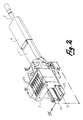
- Figure 2
- shows a slightly different inclined projection of the elevating system in the piece according to Fig. 1 (in this figure, the splinter-protection of the magazine housing is not drawn so that it does not conceal certain components),
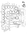
- Figure 3
- shows on enlarged scale a section of the shell magazine and other parts of the piece along the section line III-III in Fig. 2 while
- Figure 4
- shows on enlarged scale a section of the shell magazine and other parts along the section line IV-IV in Fig. 2, and
- Figure 5
- shows the rear part of the piece in question provided with a side-acting pendulum lifting arm.
- In all the figures, corresponding components have been given the same reference numbers irrespective of the different scale of the figures.
- The
complete artillery vehicle 1 shown in Fig. 1 comprises the actual dumper vehicle 2 which for its special function has been provided with an armoured personnel cab 3 which is designed so as to provide room for artillery personnel and also necessary data and communication equipment and also room for carrying out necessary firing calculations. - Also present is the
elevating system 4 which comprises the gun with itsbarrel 5 withbarrel protection 6 fixed to the gun, and two openable front hatches 6a and 6b fixed to the gun carriage, and ashell magazine 7 with splinter protection 8 which can be closed by being moved in the direction of the arrow. (In Fig. 1, the splinter protection 8 is open in order to make the top side of the magazine accessible.) Also included therein is a loading bridge 9 with accessories and also a ram 10 (see Fig. 2) and asmall standby magazine 11 for propelling powder charges. Additional propelling powder charges are carried in thestorage magazines - The purpose of the
barrel protection 6 is on the one hand to protect the recoil system of the gun from splinter and on the other hand to screen the hot barrel from the environment so that it is more difficult to locate using IR-sensitive equipment. - The
shell magazine 7 is provided internally with three guide wheels 14-16 (see Fig. 3), around which anendless chain conveyor 17, which in the examples shown consists of 24 interlinkedshell compartments 18, is arranged in a mechanically displaceable manner. Theendless chain conveyor 17 forms a continuous loop with twoportions side portions 21, 22 (an inner 21 and an outer 22) extending down along its right side. Theshell magazine housing 7 is also provided internally with guide strips 23 (a front one and a rear one) on which theshells 24 positioned in theshell compartments 18 and, respectively, theshell compartments 18 rest and along which these are displaced. - All the
shell compartments 18 are also open outwards away from the guide wheels 14-16. This means that theshell compartments 18 in theupper portion 19 of theendless chain conveyor 17 are open upwards and that the shells in this part of the magazine are supported entirely by the shell compartments which in turn rest on their own guide strip here. Any empty shell compartments can thus be filled from this side provided that theshell magazine 7 can be opened in this part. Accordingly, this can take place e.g. by means of a crane but can also take place using the pendulum arm illustrated in Figure 5. - Close to the
inner side part 21 of theendless chain conveyor 17 at the level of thelower guide wheel 16, theguide strips 23 can be opened, which means that thatshell 24 which, in itscompartment 18, is located at the level of this opening 25 when theguide strips 23 are moved aside will be transferred to the loading bridge 9 provided that this has been pivoted in towards the opening in question. From this position, the loading bridge 9 can be pivoted in towards the loading opening 26 of thebarrel 5, after which theram 10 is actuated. - In order that a high ramming rate can be used, however, it is necessary for the
shell 24 itself to have been brought together beforehand with the propelling powder charge to form an appropriately held-together unit so that these can be rammed home as a unit. The fuse of the shell must also be programmed. In this connection, refer to Fig. 4. As can be seen from this figure, a shell 24' from theshell magazine 7 has been guided down onto the loading bridge 9. The latter also has room for apropelling powder charge 28, in this case in the form of a charge case which has been supplied separately. As soon as the shell and the charge case are in position, amember 27 for combined fuse programming and bringing together is actuated, which engages over the front part of the shell, i.e. its fuse, and, at the same time as fuse programming is carried out (mechanically or electronically), moves the shell 24' in the direction of the arrow A until the shell and thepropelling powder charge 28 form an appropriately held-together unit, after which themember 27 is returned to its starting position and the loading bridge 9 is transferred to the loading position directly adjacent to the loading opening of thebarrel 5. - In Figure 5, only the rearmost part of the dumper vehicle 2 and the rearmost part of the
elevating system 4 are shown. On the other hand, theentire magazine 7, the loading bridge 9 and theram 10 and also parts of a shell 24'' lying on the loading bridge 9 and apropelling powder charge 28 " are shown. The pendulum loading arm illustrated in the figure has been given thereference number 29. It is fastened pivotably to the elevatingsystem 4 of the gun via twobearings magazine 7. Thependulum loading arm 29 has ashell cradle 33 at its free outer end. This cradle is provided with gripping members (not drawn in the figure) which hold a shell 24''' positioned in the same until the pendulum arm has reached its final position. The refilling position of thependulum loading arm 29 is drawn in broken lines in the figure. In this position, shells can be positioned in the shell cradle, after which the drive members (concealed in the figure) of the pendulum loading arm, in the form of a hydraulic piston assembly, pivots the arm up in the direction of the arrows B, past the position drawn in the figure, until theshell cradle 33 is located directly above the empty shell compartment 18', drawn in the figure, in themagazine 7. In this position, the shell-gripping members mentioned previously are released and the shell 24''' is tipped into the shell compartment 18' and thependulum loading arm 29 is returned to the starting position down between the arms of the protective frame 32, and at the same time the next empty shell compartment is advanced to the receiving position previously occupied by the shell compartment 18'. Theshell cradle 33 of the pendulum loading arm can be loaded with a new shell, either manually or mechanically, when it is in its lower refilling position between the arms of the protective frame 32. - By virtue of the fact that the direction of movement of the endless chain conveyor is optional, a promptly required shell can be conveyed to the
discharge position 25, at the same time as the specific positioning of the endless chain conveyor on the elevating system of the gun and its own special design provide a high magazine capacity and short and rapid ramming operations. The magazine is moreover easy to refill. - The magazine system outlined above is therefore effective in terms of both action and cost.
Claims (5)
- Shell magazine (7) of the endless chain conveyor type intended for preferably heavier self-propelled artillery pieces (1), comprising a number of shell compartments (18) which are arranged parallel to one another and connected, by means of links adapted thereto, to form an endless chain conveyor which is movable around guide wheels (14-16), and which compartments can each receive a shell (24), where said endless chain conveyor (17) is arranged in a magazine (7) connected rigidly to the elevating system of the gun (5), characterized in that said endless chain conveyor extends around the guide wheels (14-16) in a loop with an upper portion (19) and a lower portion (20) across the upper part of the elevating system (4) and also an outer portion (22) and an inner portion (21) down along at least one side of the elevating system, the magazine (7) having at the level of its lower part an openable and closable discharge opening (25) for discharging the shell (24') from that shell compartment (18) which is located at the level of the discharge opening (25) when it is open.
- Shell magazine according to Claim 1, characterized in that the shell compartments (18) included in the endless chain conveyor (17) are open in the outward direction away from the guide wheels (14-16) and in that the inside of the magazine (7) has guide strips (23) against which the shell compartments and, respectively, the shells located in the shell compartments can bear as necessary.
- Shell magazine (7) according to Claim 2, characterized in that the magazine (7) is designed with an openable upper part (8) and replenished by a pendulum lifting arm (29) which is fastened to the elevating system of the gun below the magazine and is pivotably movable transversely to the longitudinal direction of the gun and with which shells (24''') can be lifted mechanically from ground level up to the upper horizontal portion (19) of the endless chain conveyor (17) in order there to be transferred into an empty shell compartment (18').
- Shell magazine (7) according to one of Claims 1-3, characterized in that it is complemented by a loading bridge (9) which is displaceable from a position at the level of the discharge opening (25) of the shell magazine to a position directly adjacent to the loading opening (26) of the gun and which, in addition to room for a shell (24'), also provides space for a propelling powder charge (28), the loading bridge being complemented by a member (27) for backing up the shell (24' ) towards the propelling powder charge (28) and bringing these together to form an appropriately held-together unit before they are rammed home as a unit in the loading opening (26) of the gun (5).
- Shell magazine (7) according to Claim 4, characterized in that the member (27) for bringing together the shell (24') and the propelling powder charge (28) is also used for setting the fuse of the shell before the latter.is rammed home in the gun.
Applications Claiming Priority (2)
| Application Number | Priority Date | Filing Date | Title |
|---|---|---|---|
| SE9800207 | 1998-01-27 | ||
| SE9800207A SE9800207L (en) | 1998-01-27 | 1998-01-27 | Garnet magazine for coarser self-propelled artillery pieces |
Publications (3)
| Publication Number | Publication Date |
|---|---|
| EP0932012A2 EP0932012A2 (en) | 1999-07-28 |
| EP0932012A3 EP0932012A3 (en) | 2000-11-22 |
| EP0932012B1 true EP0932012B1 (en) | 2003-12-17 |
Family
ID=20409977
Family Applications (1)
| Application Number | Title | Priority Date | Filing Date |
|---|---|---|---|
| EP19990850004 Expired - Lifetime EP0932012B1 (en) | 1998-01-27 | 1999-01-15 | Loading system for an artillery gun |
Country Status (3)
| Country | Link |
|---|---|
| EP (1) | EP0932012B1 (en) |
| DE (1) | DE69913576T2 (en) |
| SE (1) | SE9800207L (en) |
Families Citing this family (3)
| Publication number | Priority date | Publication date | Assignee | Title |
|---|---|---|---|---|
| WO2002077564A1 (en) * | 2001-03-23 | 2002-10-03 | Nammo, Inc. | Open bolt firing mechanism for programmable cartridges |
| SE534616C2 (en) * | 2009-10-21 | 2011-10-25 | Bae Systems Bofors Ab | Automated charging magazine |
| CN115371488B (en) * | 2022-08-19 | 2023-09-29 | 西安昆仑工业(集团)有限责任公司 | Cannon loading device |
Family Cites Families (10)
| Publication number | Priority date | Publication date | Assignee | Title |
|---|---|---|---|---|
| US2773325A (en) * | 1953-06-26 | 1956-12-11 | John L Hill | Magazine and cartridge container assembly |
| FR1195834A (en) * | 1957-05-16 | 1959-11-19 | Breda Meccanica Bresciana | Magazine tank for firearms, machine guns, cannons and the like |
| CH463322A (en) * | 1963-11-13 | 1968-09-30 | Bofors Ab | Device in a mobile gun provided with a gun barrel arranged in a leveling system for lifting and advancing cartridges when loading a cartridge magazine fastened to the leveling system of the gun |
| FR2102839A5 (en) * | 1970-08-25 | 1972-04-07 | Even Georges | |
| FR2102840A5 (en) * | 1970-08-25 | 1972-04-07 | Even Georges | |
| SE391806B (en) | 1974-01-15 | 1977-02-28 | Bofors Ab | MAGAZINE FOR GROSS CALIBRIC FIREARMS |
| EP0051119B1 (en) * | 1980-08-27 | 1985-02-06 | Fmc Corporation | Automatic large caliber ammunition loading system |
| FR2520452A1 (en) * | 1982-01-21 | 1983-07-29 | France Etat | HYDRAULIC DOWNLINK AND LATCHING DEVICE AND AUTOMATIC CANON FEEDING ASSEMBLY HAVING SUCH A DEVICE |
| DE3524924C1 (en) * | 1985-07-12 | 1989-03-30 | Diehl Gmbh & Co | Armored vehicle with crested gun barrel gun |
| SE9201433L (en) | 1992-05-06 | 1993-11-07 | Bofors Ab | rammer |
-
1998
- 1998-01-27 SE SE9800207A patent/SE9800207L/en unknown
-
1999
- 1999-01-15 EP EP19990850004 patent/EP0932012B1/en not_active Expired - Lifetime
- 1999-01-15 DE DE69913576T patent/DE69913576T2/en not_active Expired - Lifetime
Also Published As
| Publication number | Publication date |
|---|---|
| EP0932012A2 (en) | 1999-07-28 |
| SE508923C2 (en) | 1998-11-16 |
| EP0932012A3 (en) | 2000-11-22 |
| DE69913576D1 (en) | 2004-01-29 |
| DE69913576T2 (en) | 2004-09-16 |
| SE9800207L (en) | 1998-11-16 |
| SE9800207D0 (en) | 1998-01-27 |
Similar Documents
| Publication | Publication Date | Title |
|---|---|---|
| US4236441A (en) | Field artillery ammunition support vehicle | |
| US4706544A (en) | Cannon loader for separate charge and projectile | |
| US5604327A (en) | Ordnance | |
| EP0105101A3 (en) | Automatic ammunition loading system for a large caliber cannon | |
| US4632011A (en) | Automatic loader for an armored vehicle having a rotatable turret | |
| US4648305A (en) | Armored vehicle for supplying ammunition to a self-propelled artillery weapon | |
| US4381693A (en) | Military equipment comprising a turret carrying an external large caliber gun | |
| GB2049120A (en) | Combat vehicle | |
| US7159504B2 (en) | Firing module | |
| US4690031A (en) | Automatic loader for an armored vehicle having a rotatable turret | |
| CA1040910A (en) | Ammunition magazine for a tank gun | |
| US4064786A (en) | Method and device for automatic ammunition handling | |
| EP0932012B1 (en) | Loading system for an artillery gun | |
| US9360266B2 (en) | Cannon and military vehicle | |
| US4836085A (en) | Magazine arrangement for a tank | |
| US4991489A (en) | Loading device | |
| US6272967B1 (en) | Modular ammunition storage and retrieval system | |
| GB1563397A (en) | Tank with a device for transferring ammunition from a magazine to a firerm on the tank | |
| KR102422095B1 (en) | Autoloaders and Vehicles Containing Autoloaders | |
| US4454799A (en) | Ammunition storage and weapon loading system | |
| GB2212891A (en) | Armoured vehicle with top-mounted barrel weapon. | |
| CA1153231A (en) | Device for automatic transfer of rounds for firearm | |
| US20240219137A1 (en) | Feeding device for loading and unloading a radially opening ammunition cup for an automatic gun loading system | |
| US20020144590A1 (en) | Automatic loading process and system for a weapon mounted on a ship | |
| RU2215965C2 (en) | Combat compartment of tank ( variants ) |
Legal Events
| Date | Code | Title | Description |
|---|---|---|---|
| PUAI | Public reference made under article 153(3) epc to a published international application that has entered the european phase |
Free format text: ORIGINAL CODE: 0009012 |
|
| AK | Designated contracting states |
Kind code of ref document: A2 Designated state(s): DE FR GB SE |
|
| AX | Request for extension of the european patent |
Free format text: AL;LT;LV;MK;RO;SI |
|
| PUAL | Search report despatched |
Free format text: ORIGINAL CODE: 0009013 |
|
| AK | Designated contracting states |
Kind code of ref document: A3 Designated state(s): AT BE CH CY DE DK ES FI FR GB GR IE IT LI LU MC NL PT SE |
|
| AX | Request for extension of the european patent |
Free format text: AL;LT;LV;MK;RO;SI |
|
| 17P | Request for examination filed |
Effective date: 20010523 |
|
| D17P | Request for examination filed (deleted) | ||
| AKX | Designation fees paid |
Free format text: DE FR GB SE |
|
| R17P | Request for examination filed (corrected) |
Effective date: 20010523 |
|
| GRAH | Despatch of communication of intention to grant a patent |
Free format text: ORIGINAL CODE: EPIDOS IGRA |
|
| GRAS | Grant fee paid |
Free format text: ORIGINAL CODE: EPIDOSNIGR3 |
|
| GRAA | (expected) grant |
Free format text: ORIGINAL CODE: 0009210 |
|
| AK | Designated contracting states |
Kind code of ref document: B1 Designated state(s): DE FR GB SE |
|
| REG | Reference to a national code |
Ref country code: GB Ref legal event code: FG4D |
|
| REF | Corresponds to: |
Ref document number: 69913576 Country of ref document: DE Date of ref document: 20040129 Kind code of ref document: P |
|
| PG25 | Lapsed in a contracting state [announced via postgrant information from national office to epo] |
Ref country code: SE Free format text: LAPSE BECAUSE OF FAILURE TO SUBMIT A TRANSLATION OF THE DESCRIPTION OR TO PAY THE FEE WITHIN THE PRESCRIBED TIME-LIMIT Effective date: 20040317 |
|
| ET | Fr: translation filed | ||
| PLBE | No opposition filed within time limit |
Free format text: ORIGINAL CODE: 0009261 |
|
| STAA | Information on the status of an ep patent application or granted ep patent |
Free format text: STATUS: NO OPPOSITION FILED WITHIN TIME LIMIT |
|
| 26N | No opposition filed |
Effective date: 20040920 |
|
| REG | Reference to a national code |
Ref country code: FR Ref legal event code: PLFP Year of fee payment: 17 |
|
| PGFP | Annual fee paid to national office [announced via postgrant information from national office to epo] |
Ref country code: DE Payment date: 20150128 Year of fee payment: 17 |
|
| PGFP | Annual fee paid to national office [announced via postgrant information from national office to epo] |
Ref country code: GB Payment date: 20150127 Year of fee payment: 17 Ref country code: FR Payment date: 20150119 Year of fee payment: 17 |
|
| REG | Reference to a national code |
Ref country code: DE Ref legal event code: R119 Ref document number: 69913576 Country of ref document: DE |
|
| GBPC | Gb: european patent ceased through non-payment of renewal fee |
Effective date: 20160115 |
|
| REG | Reference to a national code |
Ref country code: FR Ref legal event code: ST Effective date: 20160930 |
|
| PG25 | Lapsed in a contracting state [announced via postgrant information from national office to epo] |
Ref country code: DE Free format text: LAPSE BECAUSE OF NON-PAYMENT OF DUE FEES Effective date: 20160802 Ref country code: GB Free format text: LAPSE BECAUSE OF NON-PAYMENT OF DUE FEES Effective date: 20160115 |
|
| PG25 | Lapsed in a contracting state [announced via postgrant information from national office to epo] |
Ref country code: FR Free format text: LAPSE BECAUSE OF NON-PAYMENT OF DUE FEES Effective date: 20160201 |