EP0931949B1 - Slide bearing - Google Patents
Slide bearing Download PDFInfo
- Publication number
- EP0931949B1 EP0931949B1 EP99810006A EP99810006A EP0931949B1 EP 0931949 B1 EP0931949 B1 EP 0931949B1 EP 99810006 A EP99810006 A EP 99810006A EP 99810006 A EP99810006 A EP 99810006A EP 0931949 B1 EP0931949 B1 EP 0931949B1
- Authority
- EP
- European Patent Office
- Prior art keywords
- bearing
- bearing surfaces
- sliding
- nozzles
- moving body
- Prior art date
- Legal status (The legal status is an assumption and is not a legal conclusion. Google has not performed a legal analysis and makes no representation as to the accuracy of the status listed.)
- Expired - Lifetime
Links
Images


Classifications
-
- F—MECHANICAL ENGINEERING; LIGHTING; HEATING; WEAPONS; BLASTING
- F16—ENGINEERING ELEMENTS AND UNITS; GENERAL MEASURES FOR PRODUCING AND MAINTAINING EFFECTIVE FUNCTIONING OF MACHINES OR INSTALLATIONS; THERMAL INSULATION IN GENERAL
- F16C—SHAFTS; FLEXIBLE SHAFTS; ELEMENTS OR CRANKSHAFT MECHANISMS; ROTARY BODIES OTHER THAN GEARING ELEMENTS; BEARINGS
- F16C32/00—Bearings not otherwise provided for
- F16C32/06—Bearings not otherwise provided for with moving member supported by a fluid cushion formed, at least to a large extent, otherwise than by movement of the shaft, e.g. hydrostatic air-cushion bearings
- F16C32/0603—Bearings not otherwise provided for with moving member supported by a fluid cushion formed, at least to a large extent, otherwise than by movement of the shaft, e.g. hydrostatic air-cushion bearings supported by a gas cushion, e.g. an air cushion
- F16C32/0614—Bearings not otherwise provided for with moving member supported by a fluid cushion formed, at least to a large extent, otherwise than by movement of the shaft, e.g. hydrostatic air-cushion bearings supported by a gas cushion, e.g. an air cushion the gas being supplied under pressure, e.g. aerostatic bearings
- F16C32/0622—Bearings not otherwise provided for with moving member supported by a fluid cushion formed, at least to a large extent, otherwise than by movement of the shaft, e.g. hydrostatic air-cushion bearings supported by a gas cushion, e.g. an air cushion the gas being supplied under pressure, e.g. aerostatic bearings via nozzles, restrictors
-
- F—MECHANICAL ENGINEERING; LIGHTING; HEATING; WEAPONS; BLASTING
- F16—ENGINEERING ELEMENTS AND UNITS; GENERAL MEASURES FOR PRODUCING AND MAINTAINING EFFECTIVE FUNCTIONING OF MACHINES OR INSTALLATIONS; THERMAL INSULATION IN GENERAL
- F16C—SHAFTS; FLEXIBLE SHAFTS; ELEMENTS OR CRANKSHAFT MECHANISMS; ROTARY BODIES OTHER THAN GEARING ELEMENTS; BEARINGS
- F16C29/00—Bearings for parts moving only linearly
- F16C29/02—Sliding-contact bearings
- F16C29/025—Hydrostatic or aerostatic
-
- F—MECHANICAL ENGINEERING; LIGHTING; HEATING; WEAPONS; BLASTING
- F16—ENGINEERING ELEMENTS AND UNITS; GENERAL MEASURES FOR PRODUCING AND MAINTAINING EFFECTIVE FUNCTIONING OF MACHINES OR INSTALLATIONS; THERMAL INSULATION IN GENERAL
- F16C—SHAFTS; FLEXIBLE SHAFTS; ELEMENTS OR CRANKSHAFT MECHANISMS; ROTARY BODIES OTHER THAN GEARING ELEMENTS; BEARINGS
- F16C32/00—Bearings not otherwise provided for
- F16C32/06—Bearings not otherwise provided for with moving member supported by a fluid cushion formed, at least to a large extent, otherwise than by movement of the shaft, e.g. hydrostatic air-cushion bearings
- F16C32/0681—Construction or mounting aspects of hydrostatic bearings, for exclusively rotary movement, related to the direction of load
- F16C32/0696—Construction or mounting aspects of hydrostatic bearings, for exclusively rotary movement, related to the direction of load for both radial and axial load
Definitions
- the invention relates to a method for sliding bearing and a sliding bearing according to the preambles of the corresponding independent claims, see US-A-4 234 175.
- the sliding bearing according to the invention is applicable for the storage of rotating shafts or spindles or for the storage of translationally moving Bodies.
- Rotating or linearly moving machine parts become sliding (sliding bearing) stored or on freely rotating balls or rollers (rolling bearings).
- bearings are mechanically much easier compared to rolling bearings.
- plain bearings are limited mainly because of friction or Lubrication problems in the plain bearings due to the size of the adjacent and relative to each other moving storage areas (compared to the much smaller theoretically point or linear supports in rolling bearings) and because of the sliding friction (compared to the much smaller rolling friction in rolling bearings) are more difficult to solve. That's why it is an old concern of the mechanical engineering, be it for example by the development better lubricant or improved material pairings, the sliding bearing properties to improve such that plain bearings for applications become useful, in which according to the respective state of the art only proven rolling bearings.
- the object of the invention to provide a method for sliding storage and to provide a sliding bearing, such that the sliding bearing according to the invention compared with known plain bearings has improved properties especially with regard to friction or lubrication and with regard to wear.
- the sliding bearing according to the invention is intended, for example, in the application for mounting a tool or workpiece spindle in a machine tool can largely replace corresponding ball bearings.
- the invention is based on the application of fluid-dynamic laws on the technique of bearings.
- a fluid flow (Advantageously, an air flow) generated, such that through this air flow fluid dynamic, acting on the bearing surfaces forces generated become.
- the bearing surfaces of the movable and the stationary body are in this case designed such that the movable body and under the slide bearing External load to be absorbed by the fluid dynamic forces, the acting on its bearing surfaces, in a predetermined by the stationary body held in an equilibrium position, in which position it is non-contact and quasi-stable from the stationary body through a slit-shaped Cavity is spaced.
- the fluid flowing between the moving and stationary body fills up in addition to its function of generating the moving body positioning Forces also the function of a lubricant (in the case of air with extremely low friction) and at the same time the function of a coolant for Store cooling.
- Figure 1 shows a schematic representation of an axial section through a shaft 1 (rotor or moving body), which is supported by means of an exemplary embodiment of the inventive sliding bearing in a two, a receiving space forming parts 2 and 2 'existing stator.
- a bearing body 3 which is rigidly connected to the shaft (shrunk onto the shaft, for example) is provided, which is a body of revolution arranged coaxially with the shaft.
- the bearing body 3 is arranged in a corresponding receiving space in the stator 2.
- the overlapping on the fluid layer bearing surfaces L of the sliding bearing are arranged on the one hand on the surfaces of the bearing body 3 and the associated (inner) surfaces of the stator 2 in pairs opposite each other.
- the bearing surfaces L are shaped such that substantially each for a Considering any selected bearing surface area of both the rotor (Bearing body 3) and the stator 2 has a counter area, wherein a normal (perpendicular from the center of the range starting) of the considered Lager lake Kunststoffes and a normal of the corresponding counter area lying on the same straight line and facing each other are directed.
- this symmetry condition is connected to the bearing surfaces L of an inventive sliding bearing are provided, the example dess Area B on the bearing body 3 with a normal N and the opposite area B 'schematically indicated with a normal N'.
- this concerns Also, the arrangement of the holes through which bearing air is injected, as shown here by the example of the nozzles 4 and 4 '.
- the bearing body 3 shown in Figure 1 has for axial storage a radially, that is dish-shaped around the shaft extending part 3.1 and one for the radial bearing axially, that is, hollow cylindrical around the shaft 1 extending part 3.2.
- a radially that is dish-shaped around the shaft extending part 3.1
- one for the radial bearing axially that is, hollow cylindrical around the shaft 1 extending part 3.2.
- the stator 2 also has 4 holes acting as nozzles for pressing a fluid (eg air) between the bearing body 3 and the stator 2 and Exhaust ducts 5 for carrying away the between bearing body 3 and stator. 2 introduced air on.
- the nozzles could also be arranged in the bearing body be. It proves to be advantageous if the arrangement of the nozzles 4 and the Exhaust ducts 5 to each other also the above given symmetry conditions be assumed, that is, if for each in a storage area arranged nozzle and for each exhaust duct in the opposite area a corresponding nozzle and a corresponding exhaust duct is provided, such as this is shown in the embodiment according to FIG.
- the bearing surfaces L of the bearing body 3 and the bearing surfaces L of the stator 2 do not touch during operation.
- the slide bearing according to the invention is virtually frictionless and thereby not only essentially lossless operable but also essentially wear-free. This also means that the material pairing the successive sliding bearing surfaces is not relevant. Further are the properties of the inventive plain bearing substantially regardless of its location and independent of torque.
- FIGS. 2 to 4 serve to attempt to physically explain the phenomenon of the experimentally found function of the slide bearing according to the invention and its parameters and boundary conditions.
- Figures 2 and 3 show pressure and force relationships in a system in which the air of a pressure p 1 arranged through a arranged in a nozzle plate PD nozzle D, arranged substantially perpendicular to the nozzle plate PD, in a gap-shaped space between the nozzle plate PD and a counter plate PG is pressed against the pressure p 0 , which is less than p 1 (for example, against atmospheric pressure) is relaxed.
- the nozzle plate PD and the counter plate PG are close together, that is, the width of the gap between the two plates PD and PG is very small to zero. In such a case, in spite of pressure difference, substantially little to no air flows through the nozzle D.
- On the counter plate PG acts a pressure difference, which tries to push the counter plate away from the nozzle plate.
- the force K 1 acting on the counterplate PG is the pressure difference p 1 -p 0 multiplied by a surface F which is at least the cross-sectional area F D of the nozzle opening and at most the surface F P of the counterplate, depending on how the surfaces lie on one another.
- Figure 2 illustrates the static case.
- the nozzle plate PD and the counter plate PG are spaced from each other (distance d) such that air exits the nozzle D and relaxes in the space between the plates.
- the total pressure between the plates will be identical to the atmospheric pressure.
- the static pressure component P 2 is reduced by the dynamic pressure component p dyn , at atmospheric pressure, a force K 2 acting against the nozzle plate acts on the counterplate. This 'pulls' the back plate PG against the nozzle plate PD.
- the phenomenon described is known in physics as a hydrodynamic paradox. Since in operation, the nozzle opposite surface moves at great speed in one direction, other phenomena or effects that can not be explained here, have their effect.
- FIG. 4 shows, in a hypothetical transmission, the application to a bearing body 3 moved between two bearing surfaces of a stator 2, as shown in its entirety in FIG.
- a stator 2 two (on a common straight line) opposing bores or nozzles 4 are arranged, from which air is pressed into the gap-shaped cavities between the bearing body 3 and the stator 2.
- a diagram is recorded showing the presumable static pressure curve between bearing body and stator as a function of the distance between each two sliding bearing surfaces.
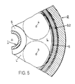
- Figure 5 shows a section of a section transverse to the axis through the sliding bearing according to Figure 1 (section line VV).
- the figure shows above all an axial plan view of the upper bearing surface L of the stator, on which the upper bearing surface of the plate-shaped bearing body part 3.1. slides.
- the fluid-dynamic effect of the air flowing out of the nozzles can be assumed to be substantially circularly symmetrical and decreases steadily with increasing distance from the nozzle due to the internal friction losses in the air, as provided.
- the effects of the individual nozzles are to be fully utilized, they are to be arranged such that their area of action (circular area on which the fluid-dynamic effect is not negligible, indicated in FIG. 5 with a dot-dash line around the nozzles 4) is not as far as possible, at least not overlap significantly.
- Experiments show that with a degree of freedom between bearing body and stator of 2 x 0.01 to 0.02 mm, at a working pressure between about 1.5 - 5 atü (1.5 to 5 ⁇ 10 5 Pa) and at an opening diameter
- This empirical value can be interpreted as the diameter of an area of activity in which the fluid-dynamic effect contributes to the function of the bearing in a manner which is not negligible. This also means that for the fullest possible utilization of the existing surfaces of a bearing body 3, the exhaust ducts 5 (here it grooves) should not be created further than about 40 mm away from the nozzles.
- the inventive Bear also external forces, such as the weight of the Rotor or load forces that act on the shaft, can absorb the fluid dynamic effective, that is overflowed with air storage areas the bearing body 3 and thus also the receiving space of the stator 2 such
- the disturbance forces only a small percentage of the fluid dynamic make out the forces generated.
- the inventive System is extremely robust against disturbing forces.
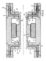
- Figure 6 shows schematically the essential parts of a spindle drive with two inventive sliding bearings, which correspond to the sliding bearing shown in the figure 1.
- At least parts of an electrically driven rotor 10 with a magnetic core 11 and bearing bodies 3 arranged at the ends are shown.
- the bearing body 3 receiving stator 2 is shown with a supplementing the driving electric motor coil 12 and a system for nozzles 4 and 5 discharges for the expanded air.
- Magnet core 11 and coil 12 together, as already said, an electric drive for driving the rotor 10.
- the degree of freedom between the rotor and stator is radially and axially 2 x 0.015 mm and the nozzles 4 have a ⁇ réellesd malmesser of about 0.5 mm.
- the air consumption of the sliding bearing according to the invention is relatively low.
- the air used should be free of solid particles, but must otherwise not specially prepared.
- FIGS. 7 and 8 also show a body 21 moved in a linear guide 20, the moving body being mounted in the linear guide according to the method according to the invention.
- Figure 7 shows a cross section through the system, in turn, bearing surfaces L, nozzles 4 and exhaust ducts 5 are shown, which meet the symmetry requirements mentioned above.
- Figure 8 is a three-dimensional representation of the system.
- the nozzles 4 are not arranged in the stationary but in the moving body, which is useful in view of the much larger extent of the bearing surfaces of the stator (linear guide) compared to the bearing surfaces of the moving body.
- FIG. 7 can also be regarded as a system of rotor 21 and stator 20.
- the bearing according to Figure 1 has the end of the rotating Shaft arranged bearing body only a radially extending, plate-shaped Part, while the function of the axially extending, hollow cylindrical Part of the wave itself is taken.
- the rotor according to FIG. 10 can be subjected to less radial load than the shaft of Figure 1, since the radially acting bearing surfaces are smaller.
Description
Die Erfindung betrifft ein Verfahren zur gleitenden Lagerung und ein Gleitlager nach den Oberbegriffen der entsprechenden, unabhängigen Patentansprüche, siehe US-A-4 234 175. Das erfindungsgemässe Gleitlager ist anwendbar zur Lagerung von rotierenden Wellen oder Spindeln oder zur Lagerung von translatorisch bewegten Körpern.The invention relates to a method for sliding bearing and a sliding bearing according to the preambles of the corresponding independent claims, see US-A-4 234 175. The sliding bearing according to the invention is applicable for the storage of rotating shafts or spindles or for the storage of translationally moving Bodies.
Rotierend oder linear bewegte Maschinenteile werden gleitend (Gleitlager) gelagert oder auf frei rotierenden Kugeln oder Rollen (Wälzlager). Gleitlager sind gegenüber Wälzlagern mechanisch bedeutend einfacher. In ihrer Anwendung aber sind Gleitlager beschränkt vor allem wegen Reibungs- bzw. Schmierproblemen, die in den Gleitlagern wegen der Grösse der aneinanderliegenden und relativ zueinander bewegten Lagerflächen (gegenüber den viel kleineren theoretisch punkt- oder linienförmigen Auflagen in den Wälzlagern) und wegen der auftretenden Gleitreibung (gegenüber der viel kleineren Rollreibung in Wälzlagern) schwieriger zu lösen sind. Aus diesem Grunde ist es ein altes Anliegen des Maschinenbaus, sei es bspw. durch die Entwicklung besserer Schmiermittel oder verbesserter Materialpaarungen, die Gleitlagereigenschaften derart zu verbessern, dass Gleitlager auch für Anwendungen brauchbar werden, in denen sich gemäss dem jeweiligen Stande der Technik nur Wälzlager bewährten. Rotating or linearly moving machine parts become sliding (sliding bearing) stored or on freely rotating balls or rollers (rolling bearings). bearings are mechanically much easier compared to rolling bearings. In her application but plain bearings are limited mainly because of friction or Lubrication problems in the plain bearings due to the size of the adjacent and relative to each other moving storage areas (compared to the much smaller theoretically point or linear supports in rolling bearings) and because of the sliding friction (compared to the much smaller rolling friction in rolling bearings) are more difficult to solve. That's why it is an old concern of the mechanical engineering, be it for example by the development better lubricant or improved material pairings, the sliding bearing properties to improve such that plain bearings for applications become useful, in which according to the respective state of the art only proven rolling bearings.
Es ist daher die Aufgabe der Erfindung, ein Verfahren zur gleitenden Lagerung und ein Gleitlager zu schaffen, derart, dass das erfindungsgemässe Gleitlager gegenüber bekannten Gleitlagern verbesserte Eigenschaften aufweist und zwar vor allem bezüglich Reibung bzw. Schmierung und bezüglich Verschleiss. Das erfindungsgemässe Gleitlager soll beispielsweise in der Anwendung zur Lagerung einer Werkzeug- oder Werkstückspindel in einer Werkzeugmaschine entsprechende Kugellager weitgehend ersetzen können.It is therefore the object of the invention to provide a method for sliding storage and to provide a sliding bearing, such that the sliding bearing according to the invention compared with known plain bearings has improved properties especially with regard to friction or lubrication and with regard to wear. The sliding bearing according to the invention is intended, for example, in the application for mounting a tool or workpiece spindle in a machine tool can largely replace corresponding ball bearings.
Diese Aufgabe wird gelöst durch das Verfahren zur gleitenden Lagerung und durch ein das Verfahren benützendes Gleitlager, wie sie durch die Patentansprüche 1 und 6 definiert sind.This object is achieved by the method for sliding storage and by a slide bearing utilizing the method as defined by the claims 1 and 6 are defined.
Die Erfindung beruht auf der Anwendung von fluiddynarnischen Gesetzmässigkeiten auf die Technik von Lagerungen. Im erfindungsgemässen Gleitlager wird zwischen einem rotierend oder linear bewegten Körper und einem stationären Körper, auf dem der bewegte Körper zu lagern ist, eine Fluidströmung (vorteilhafterweise eine Luftströmung) erzeugt, derart, dass durch diese Luftströmung fluiddynamische, auf die Lagerflächen wirkende Kräfte erzeugt werden. Die Lagerflächen des bewegbaren und des stationärem Körpers sind dabei derart ausgestaltet, dass der bewegbare Körper auch unter vom Gleitlager aufzunehmenden externen Last durch die fluiddynamischen Kräfte, die auf seine Lagerflächen wirken, in einer durch den stationären Körper vorgegebenen in Gleichgewichtsposition gehalten wird, in welcher Position er berührungslos und quasistabil vom stationären Körper durch einen spaltförmigen Hohlraum beabstandet ist.The invention is based on the application of fluid-dynamic laws on the technique of bearings. In the sliding bearing according to the invention is between a rotating or linear moving body and a stationary one Body on which the moving body is to be stored, a fluid flow (Advantageously, an air flow) generated, such that through this air flow fluid dynamic, acting on the bearing surfaces forces generated become. The bearing surfaces of the movable and the stationary body are in this case designed such that the movable body and under the slide bearing External load to be absorbed by the fluid dynamic forces, the acting on its bearing surfaces, in a predetermined by the stationary body held in an equilibrium position, in which position it is non-contact and quasi-stable from the stationary body through a slit-shaped Cavity is spaced.
Das zwischen bewegtem und stationärem Körper strömende Fluid erfüllt neben seiner Funktion zur Erzeugung der den bewegten Körper positionierenden Kräfte auch die Funktion eines Schmiermittels (im Falle von Luft mit extrem geringer Reibung) und zugleich die Funktion eines Kühlmittels zur Lagerkühlung.The fluid flowing between the moving and stationary body fills up in addition to its function of generating the moving body positioning Forces also the function of a lubricant (in the case of air with extremely low friction) and at the same time the function of a coolant for Store cooling.
Das Prinzip und beispielhafte Ausführungsformen des erfindungsgemässen Gleitlagers werden anhand der folgenden Figuren im Detail beschrieben. Dabei zeigen:
- Figur 1
- einen schematischen, axialen Schnitt durch eine beispielhafte Ausführungsform des erfindungsgemässen Gleitlagers für einen in einem Stator gelagerten Rotor;
-
Figuren 2 bis 4 - schematische Darstellungen zur Erklärung des Funktionsprinzips des erfindungsgemässen Gleitlagers;
-
Figur 5 - einen Schnitt quer zur Achse durch den Lagerkörper der Ausführungsform gemäss Figur 1 (Ausschnitt, Schnittlinie VI-VI in Figur 1);
- Figure 6
- eine Prinzip- und eine Detaildarstellung der Anwendung der Ausführungsform des erfindungsgemässen Gleitlagers gemäss Figur 1 für eine Spindel einer Werkzeugmaschine;
- Figuren 7 und 8
- in schematischer Darstellung eine beispielhafte Ausführungsform eines in einer Linearführung bewegten Körpers, wobei der Körper in der Linearführung nach dem erfindungsgemässen Verfahren gelagert ist (Figur 7: Querschnitt; Figur 8: räumliche Darstellung).
- FIG. 1
- a schematic, axial section through an exemplary embodiment of the inventive sliding bearing for a rotor mounted in a stator;
- FIGS. 2 to 4
- schematic representations to explain the principle of operation of the inventive sliding bearing;
- FIG. 5
- a section transverse to the axis through the bearing body of the embodiment according to Figure 1 (detail, section line VI-VI in Figure 1);
- Figure 6
- a schematic and a detail of the application of the embodiment of the inventive sliding bearing according to Figure 1 for a spindle of a machine tool;
- FIGS. 7 and 8
- a schematic representation of an exemplary embodiment of a moving in a linear guide body, wherein the body is mounted in the linear guide according to the inventive method (Figure 7: cross section; Figure 8: spatial representation).
Figur 1 zeigt in schematisierter Darstellung einen axialen Schnitt durch eine
Welle 1 (Rotor oder bewegter Körper), die mit Hilfe einer beispielhaften
Ausführungsform des erfindungsgemässen Gleitlagers in einem aus zwei, einen
Aufnahmeraum bildenden Teilen 2 und 2' bestehenden Stator gelagert ist.
Zur Lagerung der Welle 1 ist ein mit der Welle starr verbundener (beispielsweise
auf der Welle aufgeschrumpfter) Lagerkörper 3 vorgesehen, der ein
koaxial mit der Welle angeordneter Rotationskörper ist. Der Lagerkörper 3
ist in einem entsprechenden Aufnahmeraum im Stator 2 angeordnet. Die über
die Fluidschicht aufeinander gleitenden Lagerflächen L des Gleitlagers sind
einerseits an den Flächen des Lagerkörpers 3 und an den zugeordneten (Innen-)
Flächen des Stators 2 jeweils paarweise einander gegenüber angeordnet. Figure 1 shows a schematic representation of an axial section through a shaft 1 (rotor or moving body), which is supported by means of an exemplary embodiment of the inventive sliding bearing in a two, a receiving
Die Lagerflächen L sind derart geformt, dass im wesentlichen jeder für eine
Betrachtung beliebig ausgewählte Lagerflächenbereich sowohl des Rotors
(Lagerkörper 3) als auch des Stators 2 einen Gegenbereich aufweist, wobei
eine Normale (Senkrechte vom Mittelpunkt des Bereiches ausgehend) des betrachteten
Lagerflächenbereiches und eine Normale des entsprechenden Gegenbereiches
auf derselben Geraden liegen und einander entgegengesetzt
gerichtet sind. In der Figur 1 ist diese Symmetriebedingung, die an die Lagerflächen
L eines erfindungsgemässen Gleitlagers gestellt sind, am Beispiel dess
Bereiches B auf dem Lagerkörper 3 mit einer Normalen N und des Gegenbereiches
B' mit einer Normalen N' schematisch angedeutet. Dies betrifft
auch die Anordnung der Bohrungen, durch welche Lagerluft eingepresst wird,
wie hier am Beispiel der Düsen 4 und 4' gezeigt wird.The bearing surfaces L are shaped such that substantially each for a
Considering any selected bearing surface area of both the rotor
(Bearing body 3) and the
Durch eine derartig symmetrische Anordnung der Lagerflächen L wird erreicht, dass die Summe aller auf Lagerflächenbereich und Gegenbereich wirkenden Kräfte nahe der Gleichgewichtsposition Null wird, wenn die fluiddynamisch erzeugten Kräfte auf den Lagerflächenbereich und auf den Gegenbereich die das Gleichgewicht störenden externen Kräfte kompensieren. By such a symmetrical arrangement of the bearing surfaces L is achieved, that the sum of all acting on the bearing surface area and counter area Forces near the equilibrium position become zero when the fluid dynamic generated forces on the bearing surface area and on the opposite area compensate for the external forces disturbing the balance.
Der in der Figur 1 dargestellte Lagerkörper 3 weist für die axiale Lagerung
einen sich radial, das heisst tellerförmig um die Welle erstreckenden Teil 3.1
und einen für die radiale Lagerung sich axial, das heisst sich hohlzylinderförmig
um die Welle 1 erstreckenden Teil 3.2 auf. Für beide Teile sind die oben
angegebenen Symmetriebedingungen im wesentlichen erfüllt.The
Der Stator 2 weist ferner als Düsen 4 wirkende Bohrungen zum Einpressen
eines Fluids (bspw. Luft) zwischen den Lagerkörper 3 und den Stator 2 und
Abluftkanäle 5 zum Wegführen der zwischen Lagerkörper 3 und Stator 2
eingeleiteten Luft auf. Die Düsen könnten auch im Lagerkörper angeordnet
sein. Es erweist sich als vorteilhaft, wenn die Anordnung der Düsen 4 und der
Abluftkanäle 5 zueinander ebenfalls den oben gegebenen Symmetriebedingungen
unterstellt werden, das heisst, dass wenn für jede in einem Lagerflächenbereich
angeordnete Düse und für jeden Abluftkanal im Gegenbereich eine
entsprechende Düse und ein entsprechender Abluftkanal vorgesehen wird, wie
dies in der Ausführungsform gemäss Figur 1 gezeigt ist.The
Während der Rotation der Welle 1 wird durch die Düsen 4 Druckluft zwischen
die Lagerflächen L der beiden Lagerkörperteile 3.1 und 3.2 und des
Stators 2 gepresst, welche Luft im Lagerspalt gleichgerichtet zu den Lagerflächen
L von den Düsen zu den Abluftkanälen strömt und dadurch die gewünschte
fluiddynamische Wirkung erzeugt. Durch die fluiddynamische Wirkung
entstehen Druckverhältnisse zwischen den aufeinander gleitenden Lagerflächen,
welche den Lagerkörper 3 in einer Position halten, in der die beidseitigen
Abstände zwischen Stator 2 und Lagerkörper 3 im wesentlichen ausgeglichen
sind, das heisst, in welcher der Abstand eines betrachteten, beliebigen
Lagerflächenbereichs (z.B. B) des Rotors vom Stator im wesentlichen gleich
ist wie der Abstand des entsprechenden Gegenbereiches (z.B. B') vom Stator
2, derart also, dass der Lagerkörper 3 relativ zu einer wohldefinierten Mittellage
verharrt.During the rotation of the shaft 1 4 compressed air between through the nozzles
the bearing surfaces L of the two bearing body parts 3.1 and 3.2 and the
Das heisst mit anderen Worten, die Lagerflächen L des Lagerkörpers 3 und
die Lagerflächen L des Stators 2 berühren sich während dem Betrieb nicht.
Der einzige Widerstand, den der Lagerkörper 3 bei einer Rotation zu überwinden
hat, ist der Widerstand der zwischen den Lagerflächen L strömenden
Luft, ein Widerstand, der verglichen mit Gleitreibung zwischen festen Oberflächen
oder verglichen mit innerer Reibung in flüssigen Schmierschichten
praktisch vernachlässigbar ist. Das erfindungsgemässe Gleitlager ist quasi reibungsfrei
und dadurch nicht nur im wesentlichen verlustfrei betreibbar sondern
auch im wesentlichen verschleissfrei. Dies bedeutet auch, dass die Materialpaarung
der aufeinander gleitenden Lagerflächen nicht relevant ist. Ferner
sind die Eigenschaften des erfindungsgemässen Gleitlagers im wesentlichen
unabhängig von seiner Lage und unabhängig vom Drehmoment.In other words, the bearing surfaces L of the bearing
Figuren 2 bis 4 dienen einem Versuch, das Phänomen der experimentell gefundenen Funktion des erfindungsgemässen Gleitlagers und seine Parameter und Randbedingungen physikalisch zu erklären. FIGS. 2 to 4 serve to attempt to physically explain the phenomenon of the experimentally found function of the slide bearing according to the invention and its parameters and boundary conditions.
Figuren 2 und 3 zeigen Druck- und Kraftverhältnisse in einem System, in dem Luft eines Druckes p1 durch eine in einer Düsenplatte PD angeordneten Düse D, im wesentlichen senkrecht zur Düsenplatte PD angeordnet, in einen spaltförmigen Raum zwischen der Düsenplatte PD und einer Gegenplatte PG gepresst, gegen den Druck p0, der kleiner ist als p1 (beispielsweise gegen Atmosphärendruck) entspannt wird. Figures 2 and 3 show pressure and force relationships in a system in which the air of a pressure p 1 arranged through a arranged in a nozzle plate PD nozzle D, arranged substantially perpendicular to the nozzle plate PD, in a gap-shaped space between the nozzle plate PD and a counter plate PG is pressed against the pressure p 0 , which is less than p 1 (for example, against atmospheric pressure) is relaxed.
In der Figur 2 sind die Düsenplatte PD und die Gegenplatte PG nahe beisammen, das heisst, die Breite des Spaltes zwischen den beiden Platten PD und PG ist sehr klein bis gleich Null. In einem derartigen Falle fliesst trotz Druckdifferenz im wesentlichen wenig bis keine Luft durch die Düse D. Auf die Gegenplatte PG wirkt ein Druckunterschied, der die Gegenplatte von der Düsenplatte wegzudrücken versucht. Die auf die Gegenplatte PG wirkende Kraft K1 ist dabei die Druckdifferenz p1 - p0 multipliziert mit einer Fläche F, die mindestens die Querschnittsfläche FD der Düsenöffnung und maximal die Fläche FP der Gegenplatte ist, je nachdem, wie die Flächen aufeinanderliegen. Figur 2 illustriert den statischen Fall.In the figure 2, the nozzle plate PD and the counter plate PG are close together, that is, the width of the gap between the two plates PD and PG is very small to zero. In such a case, in spite of pressure difference, substantially little to no air flows through the nozzle D. On the counter plate PG acts a pressure difference, which tries to push the counter plate away from the nozzle plate. The force K 1 acting on the counterplate PG is the pressure difference p 1 -p 0 multiplied by a surface F which is at least the cross-sectional area F D of the nozzle opening and at most the surface F P of the counterplate, depending on how the surfaces lie on one another. Figure 2 illustrates the static case.
In Figur 3 sind die Düsenplatte PD und die Gegenplatte PG voneinander beabstandet (Abstand d), derart, dass Luft aus der Düse D austritt und sich in den Raum zwischen den Platten entspannt. Dadurch entsteht ein dynamisches System, in dem der Gesamtdruck im Raum zwischen der Düsenplatte PD und der Gegenplatte PG sich aus einem in allen Richtungen gleichförmig wirkenden statischen Anteil und einem in Strömungsrichtung wirkenden kinetischen Anteil der Strömung zusammensetzt.In Fig. 3 , the nozzle plate PD and the counter plate PG are spaced from each other (distance d) such that air exits the nozzle D and relaxes in the space between the plates. This creates a dynamic system in which the total pressure in the space between the nozzle plate PD and the counterplate PG is composed of a uniformly acting in all directions static component and a kinetic component of the flow acting in the flow direction.
Wenn die Menge der ausgeströmten Luft und die Platzverhältnisse zwischen den Platten derart gewählt werden, dass die aus der Düse austretende Luft bereits zwischen den Platten völlig (das heisst auf Atmosphärendruck) entspannen kann, ist der Gesamtdruck zwischen den Platten identisch dem Atmosphärendruck. Liegt dagegen der statische Druckanteil P2, um den dynamischen Druckanteil pdyn reduziert, unter Atmosphärendruck, so wirkt auf die Gegenplatte eine gegen die Düsenplatte wirkende Kraft K2. Diese 'zieht' die Gegenplatte PG gegen die Düsenplatte PD. Das beschriebene Phänomen ist in der Physik als hydrodynamisches Paradoxon bekannt. Da im Betriebsfall die der Düse gegenüberliegende Fläche sich mit grosser Geschwindigkeit in eine Richtung bewegt, werden noch andere Phänomene bzw. Effekte, die hier nicht erklärt werden können, ihre Wirkung haben.If the amount of air discharged and the space between the plates are chosen such that the air exiting the nozzle can already fully relax (i.e., at atmospheric pressure) between the plates, the total pressure between the plates will be identical to the atmospheric pressure. On the other hand, if the static pressure component P 2 is reduced by the dynamic pressure component p dyn , at atmospheric pressure, a force K 2 acting against the nozzle plate acts on the counterplate. This 'pulls' the back plate PG against the nozzle plate PD. The phenomenon described is known in physics as a hydrodynamic paradox. Since in operation, the nozzle opposite surface moves at great speed in one direction, other phenomena or effects that can not be explained here, have their effect.
Bei einem Übergang vom statischen Fall gemäss Figur 2 zum dynamischen Fall gemäss Figur 3 durch sukzessive Vergrösserung des Abstandes d zwischen den Platten sinkt also der statische Druck zwischen den Platten von p1 auf p2 und kehrt sich in eine auf die Gegenplatte PG wirkende Druckkraft um (K1 von der Düsenplatte wegweisend; K2 gegen die Düsenplatte weisend). Dabei wird der minimale statische Druck (maximale Kraft K2) bei einer zwar kleinen aber offenbar doch messbaren Spaltbreite erreicht und ändert sich bei einer weiteren Verbreiterung innerhalb der kritischen Grösse bzw. der experimentierten minimalen bis maximalen Spaltbreite bzw. des Plattenabstands d nicht mehr.In the case of a transition from the static case according to FIG. 2 to the dynamic case according to FIG. 3 by successive enlargement of the distance d between the plates, the static pressure between the plates drops from p 1 to p 2 and turns into a compressive force acting on the counterplate PG (K 1 pointing away from the nozzle plate, K 2 pointing towards the nozzle plate). In this case, the minimum static pressure (maximum force K 2 ) is achieved with a small but apparently measurable gap width and no longer changes with a further broadening within the critical size or the experimented minimum to maximum gap width or the plate spacing d.
Versuche haben ergeben, dass bei dem erfindungsgemässen Gleitlager bei einem Abstand oder Gleitlagerspalt von weniger als 5µm vermutlich durch Drosselungseffekte ein Druck entsteht, der zwischen den Platten eine Abstossung bewirkt. Bei einem Abstand über 5µm tritt die oben diskutierte Umkehrung der Wirkung ein. Der experimentierte optimale Leistungsbereich liegt bei einer Spaltbreite von ungefähr 10 µm.Experiments have shown that in the inventive slide bearing at a distance or sliding bearing gap of less than 5μm probably through Throttling effects a pressure that creates a repulsion between the plates causes. At a distance above 5μm, the inverse discussed above occurs the effect. The experimented optimal power range lies at a gap width of about 10 μm.
Figur 4 zeigt nun, in hypothetischer Übertragung, die Anwendung auf einen
sich zwischen zwei Lagerflächen eines Stators 2 bewegten Lagerkörpers 3, wie
er in ganzer Gestalt in Figur 1 dargestellt ist. Im Stator 2 sind zwei (auf einer
gemeinsamen Gerade) einander gegenüberliegende Bohrungen bzw. Düsen 4
angeordnet, aus denen Luft in die spaltförmigen Hohlräume zwischen Lagerkörper
3 und Stator 2 gepresst wird. Unterhalb dem Ausschnitt von Lagerkörper
und Stator ist ein Diagramm aufgezeichnet, das den vermutlichen statischen
Druckverlauf zwischen Lagerkörper und Stator als Funktion des Abstandes
zwischen je zwei aufeinander gleitenden Lagerflächen zeigt. FIG. 4 shows, in a hypothetical transmission, the application to a
Aus dieser Figur ist ersichtlich, dass der Lagerkörper 3 (in Abwesenheit von
externen Kräften) dann eine definierte, kräftefreie Position zwischen den
Lagerflächen des Stators einnimmt, wenn der Freiheitsgrad (Abstand d) zwischen
Lagerkörper 3 und Stator 2 nicht grösser ist als zweimal Abstand d, der
in demjenigen Bereiche liegt, in dem der statische Druck noch vom Abstand
abhängig ist, vorteilhafterweise zweimal der grösst mögliche derartige Abstand.
Es geht ebenfalls aus der Darstellung hervor, dass im Falle eines Freiheitsgrades,
der zwei Abständen in einem Bereich, in dem der statische Druck
nicht mehr vom Abstand abhängig ist (dünnere Lagerkörper als der in der
Figur 5 dargestellte), eine Vielzahl von kräftefreien Positionen möglich ist,
das heisst auch Positionen, in denen die Lagerflächen von Lagerkörper und
Stator temporär nicht parallel zueinander verlaufen (bspw. durch radiale
Auslenkungen, hervorgerufen durch Bearbeitungskräfte am Werkzeug). Eine
minimale Spaltbreite (kleiner 5µm) bleibt jedoch durch den Druckaufbau
durch Drosselungskräfte stets erhalten und wirkt als Gegenkraft bei arbeitsbedingten
Auslenkungen aus der Gleichgewichtslage.From this figure it can be seen that the bearing body 3 (in the absence of
external forces) then a defined, force-free position between the
Bearing surfaces of the stator occupies when the degree of freedom (distance d) between
Versuche mit einem erfindungsgemässen Gleitlager gemäss Figur 1 haben
ergeben, dass bei der Verwendung von Luft als strömendes Fluid ein Freiheitsgrad
zwischen Lagerkörper 3 und Stator 2 von 0,02 bis 0,04 mm (2 x 0,01
bis 0,02 mm) einen optimalen Betrieb ergeben. Versuche wurden gemacht mit
einem Freiheitsgrad von 10 µm (2 x 0,005 mm) bis zu einem Freiheitsgrad
von 0,5 mm (2 x 0,25 mm). Aus diesem Versuchsergebnis lässt sich schliessen,
dass der statische Druck p2 bei Spaltweiten bis zu einer Grössenordnung von
0,01 bis 0,02 mm von dieser Spaltbreite abhängig ist. Experiments with a slide bearing according to the invention according to Figure 1 have shown that when using air as flowing fluid, a degree of freedom between bearing
Es kann angenommen werden, dass der Effekt der Abhängigkeit des statischen
Druckes und damit der Abhängigkeit der auf die Lagerflächen wirkenden
Kräfte von der Grösse des Abstandes zwischen den Lagerflächen und die
konsequente Ausnützung dieses Effektes das erfindungsgemässe Verfahren zur
gleitenden Lagerung ermöglicht. Durch diesen Effekt entsteht ein sich selbst
zentrierendes System, in dem auf den Lagerkörper 3, sobald er sich aus seiner
Gleichgewichtslage entfernt, eine rückstellende Kraft wirkt. Ein ähnliches
System, in dem zwischen den Lagerflächen ein Überdruck (Luftkissen) erzeugt
wird, dessen Druckverhältnisse wegen des höheren statischen Zustandes nicht
von der Spaltbreite abhängig sind, hat keine selbstzentrierende Wirkung und
kann aus diesem Grunde nicht so funktionieren, wie die Erfindung es zeigt.It can be assumed that the effect of the dependence of the static
Pressure and thus the dependence of acting on the bearing surfaces
Forces of the size of the distance between the bearing surfaces and the
Consistent exploitation of this effect, the inventive method for
sliding storage allows. This effect creates a self
centering system, in which on the
Figur 5 zeigt einen Ausschnitt aus einem Schnitt quer zur Achse durch das
Gleitlager gemäss Figur 1 (Schnittline V-V). Die Figur zeigt vor allem eine
axiale Draufsicht auf die obere Lagerfläche L des Stators, auf der die obere
Lagerfläche des tellerförmigen Lagerkörperteils 3.1. gleitet. Es sind zwei Düsen
4 und zwei Abluftkanäle 5 sichtbar. Die fluiddynamische Wirkung der aus
den Düsen ausströmenden Luft kann im wesentlichen als kreissymmetrisch
angenommen werden und nimmt mit grösser werdendem Abstand von der
Düse wegen der inneren Reibungsverluste in der Luft, wie vorgesehen, stetig
ab. Figure 5 shows a section of a section transverse to the axis through the sliding bearing according to Figure 1 (section line VV). The figure shows above all an axial plan view of the upper bearing surface L of the stator, on which the upper bearing surface of the plate-shaped bearing body part 3.1. slides. There are two
Sollen die Wirkungen der einzelnen Düsen voll ausgenützt werden, sind sie
derart anzuordnen, dass ihre Wirkungsfläche (kreisförmige Fläche, auf der die
fluiddynamische Wirkung nicht vernachlässigbar ist, in Figur 5 mit einer
strichpunktierten Kreislinie um die Düsen 4 angedeutet) einander möglichst
nicht, jedenfalls nicht wesentlich überschneiden. Versuche zeigen, dass bei
einem Freiheitsgrad zwischen Lagerkörper und Stator von 2 x 0,01 bis 0,02
mm, bei einem Arbeitsdruck zwischen ca. 1,5 - 5 atü (1,5 bis 5·105 Pa) und
bei einem Öffnungsdurchmesser der Düse von ca. 0,5 mm mit einem Abstand
zwischen benachbarten Düsen (bis zu 100 mm) im Versuchsaufbau von ca. 80
mm gute Wirkungen erzielt werden. Dieser Erfahrungswert kann gedeutet
werden als Durchmesser eines Wirkungskreises, in dem die fluiddynamische
Wirkung in nicht vernachlässigbarer Weise zur Funktion des Lagers beiträgt.
Dies bedeutet auch, dass zur möglichst vollen Ausnützung der vorhandenen
Flächen eines Lagerkörpers 3, die Abluftkanäle 5 (hier sind es Nuten) nicht
weiter als etwa 40 mm von den Düsen entfernt angelegt sein sollten.If the effects of the individual nozzles are to be fully utilized, they are to be arranged such that their area of action (circular area on which the fluid-dynamic effect is not negligible, indicated in FIG. 5 with a dot-dash line around the nozzles 4) is not as far as possible, at least not overlap significantly. Experiments show that with a degree of freedom between bearing body and stator of 2 x 0.01 to 0.02 mm, at a working pressure between about 1.5 - 5 atü (1.5 to 5 · 10 5 Pa) and at an opening diameter The nozzle of about 0.5 mm with a distance between adjacent nozzles (up to 100 mm) in the experimental setup of about 80 mm good effects can be achieved. This empirical value can be interpreted as the diameter of an area of activity in which the fluid-dynamic effect contributes to the function of the bearing in a manner which is not negligible. This also means that for the fullest possible utilization of the existing surfaces of a
Streng genommen gelten die im Zusammenhang mit der Figur 1 aufgestellten Symmetriebedingungen nicht für die ganzen Lagerflächen sondern nur für diejenigen Lagerflächenbereiche, über denen Fluidströmungen erzeugt werden, über die sich also ein fluiddynamischer Wirkungskreis erstreckt und nur dann wenn die fluiddynamische Wirkung in allen diesen Kreisen dieselbe ist. Verallgemeinert gilt, dass die Lagerflächen des bewegten Körpers und die Fluidströme derart aufeinander abzustimmen sind, dass der angeströmte bewegte Körper in seiner im Stator zentrierten (Mittel-) Lage im wesentlichen kräftefrei, das heisst im Gleichgewicht ist.Strictly speaking, the statements made in connection with FIG Symmetry conditions not for the whole storage area but only for those bearing surface areas over which fluid flows are generated, over which therefore a fluid-dynamic sphere extends and only when the fluid dynamic effect is the same in all these circles. Generalized is that the bearing surfaces of the moving body and the Fluid flows are tuned to each other so that the flowed moving Body in its centered in the stator (middle) position substantially free of forces, that means in equilibrium.
Bei den obigen Betrachtungen wurde ein Zustand des betrachteten Lagers
ohne externe (z.B. radiale) Krafteinwirkung vorausgesetzt. Damit das erfindungsgemässe
Lager auch externe Kräfte, wie beispielsweise das Gewicht des
Rotors oder Belastungskräfte, die auf die Welle wirken, aufnehmen kann, sind
die fluiddynamisch wirksamen, das heisst mit Luft überströmten Lagerflächen
des Lagerkörpers 3 und damit auch des Aufnahmeraums des Stators 2 derart
gross zu wählen, dass die Störkräfte nur einen kleinen Prozentsatz der fluiddynamisch
erzeugten Kräfte ausmachen. Das heisst mit anderen Worten, dass
für ein höher belastetes Lager mehr "Tragfläche" also ein grösseres Lagerkörper/Stator-Paar
zur Verfügung zu stellen ist. Es hat sich gezeigt, dass bei den
oben angegebenen Abmessungen radiale Kräfte bis zu 25 kp aufgenommen
werden können. Verglichen mit üblichen arbeitsmässigen radialen Auslenkkräften
an einer Frässpindel von 25 bis 250 Pond, sieht man, dass das erfinderische
System ausserordentlich robust gegen Störkräfte ist.In the above considerations, a condition of the bearing under consideration
assuming no external (e.g., radial) force. Thus, the inventive
Bear also external forces, such as the weight of the
Rotor or load forces that act on the shaft, can absorb
the fluid dynamic effective, that is overflowed with air storage areas
the bearing
Für Arbeitsbedingungen mit kleinen externen Störkräften sind ohne weiteres Systeme mit wesentlich kleinerflächigen Lagerkörpern mit entsprechenden Abständen der Düsen und Abluftkanälen möglich.For working conditions with small external disturbance forces are readily available Systems with much smaller bearing bodies with corresponding Distances between the nozzles and exhaust ducts possible.
Figur 6 zeigt schematisch die wesentlichen Teile eines Spindelantriebs mit
zwei erfindungsgemässen Gleitlagern, die dem in der Figur 1 dargestellten
Gleitlager entsprechen. Es sind mindestens Teile eines elektrisch angetriebenen
Rotors 10 mit einem Magnetkern 11 und an den Enden angeordneten
Lagerkörpern 3 dargestellt. Ferner ist ein die Lagerkörper 3 aufnehmender
Stator 2 mit einer den antreibenden Elektromotor ergänzenden Spule 12 und
einer Anlage für Düsen 4 und Ableitungen 5 für die entspannte Luft dargestellt.
Magnetkern 11 und Spule 12 stellen zusammen, wie schon gesagt, einen
Elektroantrieb für den Antrieb des Rotors 10 dar. Der Freiheitsgrad zwischen
Rotor und Stator beträgt radial und axial 2 x 0,015 mm und die Düsen 4
haben einen Öffnungsddurchmesser von ca 0,5mm. Durch diese Düsen wird
Luft von einem Betriebsdruck von bspw. 4 atü (4·105 Pa) nahezu auf Atmosphärendruck
entspannt. Die Spindel wird mit 30,000 bis 40'000 U/min betrieben.
Es zeigt sich, dass die dargestellte Spindel unter den angegebenen Bedingungen
auch unter der Wirkung von radial wirkenden Störkräften bis zu 25 kp
(250 N) störungsfrei arbeitet. Normale, auf Werkzeugspindeln wirkende Radialkräfte
sind in der Grössenordnung von ca. 0,5 kp (5 N). Man erkennt hier
wieder die symmetrische Anordnung, insbesondere der sich gegenübergestellten
bzw. angeordneten und entgegen auf den Lagerkörper wirkenden Düsen
und den in jeweils gleichen Abständen von den Düsen angeordneten Abluftkanäle. Figure 6 shows schematically the essential parts of a spindle drive with two inventive sliding bearings, which correspond to the sliding bearing shown in the figure 1. At least parts of an electrically driven
Der Luftverbrauch des erfindungsgemässen Gleitlagers ist verhältnismässig gering. Die verwendete Luft soll frei von festen Partikeln sein, muss aber sonst nicht speziell aufbereitet werden.The air consumption of the sliding bearing according to the invention is relatively low. The air used should be free of solid particles, but must otherwise not specially prepared.
Figuren 7 und 8 zeigen noch einen in einer Linearführung 20 bewegten Körper
21, wobei der bewegte Körper in der Linearführung nach dem erfindungsgemässen
Verfahren gelagert ist. Figur 7 zeigt einen Querschnitt durch das
System, in dem wiederum Lagerflächen L, Düsen 4 und Abluftkanäle 5 dargestellt
sind, die die eingangs genannten Symmetrieanforderungen erfüllen.
Figur 8 ist eine dreidimensionale Darstellung des Systems. Im Unterschied
zum Gleitlager gemäss Figur 1, sind die Düsen 4 nicht im stationären sondern
im bewegten Körper angeordnet, was angesichts der viel grösseren Ausdehnung
der Lagerflächen des Stators (Linearführung) im Vergleich zu den Lagerflächen
des bewegten Körpers sinnvoll ist. FIGS. 7 and 8 also show a
Figur 7 kann auch als System von Rotor 21 und Stator 20 aufgefasst werden.
Im Gegensatz zum Lager gemäss Figur 1 hat der am Ende der rotierenden
Welle angeordnete Lagerkörper nur einen sich radial erstreckenden, tellerförmigen
Teil, während die Funktion des sich axial erstreckenden, hohlzylindrischen
Teils von der Welle selbst übernommen wird. Nach dem bereits Gesagten,
kann der Rotor gemäss Figur 10 radial weniger stark belastet werden als
die Welle der Figur 1, da die radial wirkenden Lagerflächen kleiner sind.FIG. 7 can also be regarded as a system of
Im erfindungsgemässen Gleitlager werden zwischen den aufeinander gleitenden Lagerflächen (L) eines bewegbaren Körpers (1/3) und eines stationären Körpers (2) Luftströmungen erzeugt, indem Druckluft durch Düsen (4) zwischen den Lagerflächen (L) gegen Atmosphärendruck entspannt wird. Durch diese Luftströmungen wird der statischen Druck zwischen den Lagerflächen (L) reduziert, sodass zwischen dem bewegten und dem stationären Körper wirkende Druckkräfte entstehen. Die Lagerflächen (L) und die Luftströmungen sind dabei derart aufeinander abgestimmt, dass der bewegbare Körper (1/3) in einem kräftefreien Gleichgewichtszustand ist, wenn er eine Position einnimmt, in der die Lagerflächen (L) des bewegbaren Körpers (1/3) die Lagerflächen (L) des stationären Körpers (2) nicht berühren. Damit die Gleichgewichtsposition eine definierte ist, ist es vorteilhaft, das Freiheitsgrad zwischen bewegbarem Körper (1/3) und stationärem Körper (2) derart zu wählen, dass jede mögliche Veränderung der Abstände zwischen den Lagerflächen eine gegenwirkende Veränderung der Druckverhältnisse bewirkt. Für Luftströmungen sind Abstände von ca. 0,01 bis 0,02 mm geeignet. Damit das Gleitlager externe Kräfte aufnehmen kann, ist es vorteilhaft, zur Vergrösserung der Druckkräfte die Lagerflächen zu vergrössern. Das Gleitlager ist quasi reibungsfrei und quasi verschleissfrei. Es eignet sich für die Lagerung von rotierenden oder linear bewegten Maschinenteilen, z.B. für die Lagerung von Spindeln in Werkzeugmaschinen.In the sliding bearing according to the invention, sliding between each other Bearing surfaces (L) of a movable body (1/3) and a stationary one Body (2) generates air currents by passing compressed air through nozzles (4) between the bearing surfaces (L) is relaxed against atmospheric pressure. By these air currents will be the static pressure between the bearing surfaces (L) reduces, so that between the moving and the stationary body acting pressure forces arise. The bearing surfaces (L) and the air currents are coordinated so that the movable body (1/3) is in a force-free state of equilibrium when he is in a position occupies, in which the bearing surfaces (L) of the movable body (1/3) the Do not touch the bearing surfaces (L) of the stationary body (2). So that Equilibrium position is a defined, it is advantageous to the degree of freedom between movable body (1/3) and stationary body (2) in such a way Choose that any change in the distances between the storage areas causes a counteracting change in the pressure conditions. For Air flows are distances of about 0.01 to 0.02 mm suitable. So that Slide bearing can absorb external forces, it is beneficial to magnification the pressure forces to enlarge the storage areas. The plain bearing is quasi frictionless and virtually wear-free. It is suitable for storage of rotating or linearly moving machine parts, e.g. for the storage of Spindles in machine tools.
Claims (15)
- Method for bringing about a sliding bearing of a body (1/3,21) movable in rotary or linear manner in a stationary body (2,20), corresponding bearing surfaces (L) of the movable body and the stationary body sliding on one another by means of a lubricant, wherein between the bearing surfaces (L) sliding on one another are produced fluid flows, through which the static pressure (P2) between the bearing surfaces (L) sliding on one another are reduced and between the stationary body and the moving body (1/3, 21) compressive forces occur, the fluid flows and bearing surfaces being matched to one another in such a way that all the compressive forces acting on the moving body are substantially mutually cancelled out, as soon as the moving body (1/3, 21) is positioned in an equilibrium position not contacting the stationary body (2, 20) and on deflection from this position opposing forces occur, the bearing surfaces (L) of the moved body (1/3, 21) being shaped such that substantially every bearing surface area (B) has a counter area (B') corresponding to it and the normals (N and N') of the bearing surface area (B) and the counter area (B') lie on the same straight line and have opposing directions, and wherein air is pressed between the bearing surfaces (L) through nozzles (4) in a substantially vertical direction to the bearing surfaces (L), characterized in that the fluid flows above each bearing surface area (B) are maintained identical to the fluid flows above the corresponding counter areas (B'), by arranging the nozzles (4) identically on bearing surface areas (B) and counter areas (B') and by ventilation of the spaces between the bearing surfaces through ventilation channels (5), wherein corresponding ventilation channels (5) are provided for bearing surface areas and counter areas and wherein the nozzles (4) are arranged centrally between the ventilation channels (5).
- Method according to claim 1, characterized in that the degree of freedom between the stationary body (2, 20) and the moving body (1/3, 21) is chosen in such a way that the spacings between the bearing surfaces (L) of the stationary body and the bearing surfaces of the moving body sliding thereon are so small that any deflection of the moving body (1/3, 21) from its equilibrium position modifies the pressure ratios between the bearing surfaces.
- Method according to claim 2, characterized in that the fluid flows are air flows and that the degree of freedom between the moving body (1/3, 21) and stationary body (2, 20) is chosen in such a way that the average spacing (d) between bearing surfaces (L) sliding on one another is 0.005 to 0.05 mm, preferably 0.01 to 0.02 mm.
- Method according to claim 3, characterized in that for producing the fluid flows air is expanded through nozzles (4) from a pressure of at least 1.5 atm (1.5 105 Pa) to atmospheric pressure and that the nozzles have an opening diameter of approximately 0.5 mm.
- Method according to one of the claims 1 to 4, characterized in that for a given operating pressure the size of the overflowed bearing surfaces is so matched to the external disturbance forces, that the disturbance forces represent a small percentage of the compressive forces (K2).
- Sliding bearing for seating a body (1/3, 21) movable in rotary or linear manner in a stationary body (2, 20), corresponding bearing surfaces (L) of the movable body and the stationary body sliding on one another, wherein the sliding bearing has means for producing fluid flows between bearing surfaces (L) sliding on one another in such a way that the movable body can remain in an equilibrium position, wherein the bearing surfaces (L) of the movable body (1/3, 21) are shaped such that substantially every bearing surface area (B) has a counter area (B') corresponding to it and the normals (N and N') of the bearing surface area (B) and the counter area (B') lie on the same straight line and have opposing directions, and wherein air is pressed between the bearing surfaces (L) through nozzles (4) in a substantially vertical direction to the bearing surfaces (L), characterized in that the nozzles (4) are arranged identically on bearing surface areas (B) and counter areas (B') and that for ventilation of the spaces between the bearing surfaces, corresponding ventilation channels (5) are provided for bearing surface areas (B) and counter areas (B') are provided, the nozzles (4) being arranged centrally between the ventilation channels (5).
- Sliding bearing according to claim 6, characterized in that the degree of freedom between the moving body (1/3, 21) and stationary body (2, 20) is such that the average spacing (d) between bearing surfaces (L) sliding on one another is 0.005 to 0.1 mm, preferably 0.01 to 0.02 mm.
- Sliding bearing according to claim 6 or 7, characterized in that the nozzles (4) are placed on the bearing surfaces (L) with spacings of at least 80 mm.
- Sliding bearing according to one of the claims 6 to 8, characterized in that for enlarging the bearing surfaces (L) and consequently increasing the compressive forces (K2) on the movable body (1/3, 21), bearing bodies (3) are fixed and the bearing surfaces (L) are located on them.
- Sliding bearing according to claim 9, characterized in that the moving body is a rotary shaft (1) and that on the latter is coaxially arranged a rotary body as the bearing body (3).
- Sliding bearing according to claim 10, characterized in that the at least one bearing body (3) has for the axial bearing of the shaft a plate-shaped part (3.1) extending radially away from the shaft (1) and for the radial bearing of the shaft (1) an axially extending, hollow cylindrical part (3.2).
- Sliding bearing according to claim 10 or 11, characterized in that the nozzles (4) are located in the bearing surfaces (L) of the stationary body (2).
- Sliding bearing according to one of the claims 6 to 8, characterized in that the stationary body (20) is a linear guide and that the moving body (21) is linearly movable in the linear guide.
- Sliding bearing according to claim 13, characterized in that the nozzles (4) are placed in the bearing surfaces (L)of the movable bearing body (21).
- Use of a bearing according to one of the claims 6 to 14 for mounting a tool spindle in a machine tool.
Applications Claiming Priority (2)
| Application Number | Priority Date | Filing Date | Title |
|---|---|---|---|
| CH16198 | 1998-01-23 | ||
| CH00161/98A CH693071A5 (en) | 1998-01-23 | 1998-01-23 | Bearings. |
Publications (2)
| Publication Number | Publication Date |
|---|---|
| EP0931949A1 EP0931949A1 (en) | 1999-07-28 |
| EP0931949B1 true EP0931949B1 (en) | 2005-06-22 |
Family
ID=4180651
Family Applications (1)
| Application Number | Title | Priority Date | Filing Date |
|---|---|---|---|
| EP99810006A Expired - Lifetime EP0931949B1 (en) | 1998-01-23 | 1999-01-06 | Slide bearing |
Country Status (6)
| Country | Link |
|---|---|
| US (1) | US6149306A (en) |
| EP (1) | EP0931949B1 (en) |
| JP (1) | JPH11257346A (en) |
| CH (1) | CH693071A5 (en) |
| DE (1) | DE59912192D1 (en) |
| ES (1) | ES2245080T3 (en) |
Families Citing this family (7)
| Publication number | Priority date | Publication date | Assignee | Title |
|---|---|---|---|---|
| ITPR20000040A1 (en) * | 2000-06-27 | 2001-12-27 | Sasib Labelling Machinery S P | CUTTING ROLL IN A LABELING MACHINE WITH CONTINUOUS INTRODUCTION OF A FILM OF LABELS IN THE REEL |
| US20040042689A1 (en) * | 2002-08-30 | 2004-03-04 | Hardinge Inc. | Hydrostatic bearing for linear motion guidance |
| DE102005023998A1 (en) | 2005-05-25 | 2006-12-14 | Schaeffler Kg | Hydrostatic storage |
| CN104428545A (en) | 2012-07-05 | 2015-03-18 | 米内斯图股份公司 | Arrangement for a self-lubricating bearing |
| TW201504538A (en) * | 2013-07-17 | 2015-02-01 | Metal Ind Res & Dev Ct | Hydrostatic bearing |
| CN105387071B (en) * | 2015-12-23 | 2018-12-04 | 无锡三虹重工机械设备有限公司 | A kind of guiding device convenient for safeguarding |
| US10704598B1 (en) * | 2019-03-05 | 2020-07-07 | Hiwin Technologies Corp. | Hydrostatic linear guideway |
Family Cites Families (18)
| Publication number | Priority date | Publication date | Assignee | Title |
|---|---|---|---|---|
| DE2252495A1 (en) * | 1972-10-26 | 1974-05-02 | Skf Kugellagerfabriken Gmbh | HYDRO OR AEROSTATIC BEARING |
| US3998502A (en) * | 1972-10-26 | 1976-12-21 | Skf Industrial Trading And Development Company, B.V. | Fluid bearing system |
| JPS5485678A (en) * | 1977-12-20 | 1979-07-07 | Canon Inc | High accuracy alignment method for air bearing guide system xy stage |
| JPS566919A (en) * | 1979-06-26 | 1981-01-24 | Canon Inc | Fluid bearing |
| JPS59190512A (en) * | 1983-04-08 | 1984-10-29 | Nippon Seiko Kk | Sliding bearing of dynamic pressure type |
| JPS6014614A (en) * | 1983-07-04 | 1985-01-25 | Hitachi Ltd | Dynamic pressure gaseous bearing |
| JPS6069557U (en) * | 1983-10-14 | 1985-05-17 | マイクロ精機株式会社 | air bearing type phono motor |
| JPS60150950A (en) * | 1984-01-20 | 1985-08-08 | Hitachi Ltd | Guiding device |
| JPS61103011A (en) * | 1984-10-24 | 1986-05-21 | Hitachi Ltd | Static gas bearing |
| US4606587A (en) * | 1985-01-08 | 1986-08-19 | Automated Quality Technologies, Inc. | Precision air slide |
| JPS63203918A (en) * | 1987-02-19 | 1988-08-23 | Ntn Toyo Bearing Co Ltd | Orifice type static pressure gas journal bearing |
| US4828403A (en) * | 1987-04-03 | 1989-05-09 | Schwartzman Everett H | Resiliently mounted fluid bearing assembly |
| JP2870749B2 (en) * | 1987-10-31 | 1999-03-17 | 株式会社島津製作所 | Air conditioner for aircraft |
| JPH0257723A (en) * | 1988-08-19 | 1990-02-27 | Kuroda Precision Ind Ltd | Static pressure gas bearing |
| JP2724349B2 (en) * | 1990-01-17 | 1998-03-09 | 黒田精工株式会社 | Hydrostatic air bearing |
| US5104237A (en) * | 1990-11-08 | 1992-04-14 | Advanced Engineering Systems Operations & Products, Inc. (Aesop) | Self-compensating hydrostatic linear motion bearing |
| JP3609455B2 (en) * | 1994-08-12 | 2005-01-12 | Ntn株式会社 | Static pressure gas bearing |
| JPH09257037A (en) * | 1996-03-26 | 1997-09-30 | Toshiba Mach Co Ltd | Spindle head for machine tool |
-
1998
- 1998-01-23 CH CH00161/98A patent/CH693071A5/en not_active IP Right Cessation
-
1999
- 1999-01-06 EP EP99810006A patent/EP0931949B1/en not_active Expired - Lifetime
- 1999-01-06 DE DE59912192T patent/DE59912192D1/en not_active Expired - Lifetime
- 1999-01-06 ES ES99810006T patent/ES2245080T3/en not_active Expired - Lifetime
- 1999-01-19 US US09/233,248 patent/US6149306A/en not_active Expired - Lifetime
- 1999-01-25 JP JP11016011A patent/JPH11257346A/en active Pending
Also Published As
| Publication number | Publication date |
|---|---|
| EP0931949A1 (en) | 1999-07-28 |
| JPH11257346A (en) | 1999-09-21 |
| ES2245080T3 (en) | 2005-12-16 |
| CH693071A5 (en) | 2003-02-14 |
| DE59912192D1 (en) | 2005-07-28 |
| US6149306A (en) | 2000-11-21 |
Similar Documents
| Publication | Publication Date | Title |
|---|---|---|
| EP3793630B1 (en) | Rotor bearing arrangement | |
| EP0158242B1 (en) | Sliding contact bearing for radial load | |
| DE102005007297A1 (en) | Fluid dynamic air bearing system for pivotal mounting of an engine | |
| DE10215738A1 (en) | Multi-disc clutch assembly with rheological thin film | |
| EP2985893A1 (en) | Electric machine with controlled air gap | |
| DE4401262C2 (en) | Aerostatic and aerodynamic mounting of an engine | |
| EP0931949B1 (en) | Slide bearing | |
| WO2003085237A1 (en) | Electromagnetic hydraulic valve, in particular proportional valve for controlling a device for adjusting the rotational angle of a camshaft in an internal combustion engine, and method for the production thereof | |
| DE4234524C2 (en) | Hybrid storage unit | |
| DE3914552A1 (en) | ROLLING BEARING | |
| WO2008095460A1 (en) | Rolling bearing which can be braked | |
| DE102017124187A1 (en) | A method for producing one or more concave recesses on a particular substantially cylindrical base body in particular on a magnet armature, plunger or a return plate, armature, plunger or return plates, which has one or more recesses produced by this method, and electro-magnetic actuator with a Such magnet armature and / or such a return plate | |
| DE3418621A1 (en) | Rolling bearing | |
| DE19920264B4 (en) | Tool holder for a high-frequency spindle | |
| DE102007054308A1 (en) | Drive device for EDM tools | |
| EP0971160B1 (en) | Actuated valve for piston compressor | |
| DE102013217396B4 (en) | planet carrier | |
| EP0619862B1 (en) | Damper for linear rolling bearing guides | |
| DE102007014845B4 (en) | Fluid dynamic bearing | |
| EP3583324B1 (en) | X-ray computer tomographic device and method for operating a x-ray computer tomographic device | |
| DE3531720A1 (en) | HYDRODYNAMIC FLUID FILM BEARING | |
| DE2352520B1 (en) | Hydrostatic piston engine | |
| DE102021102012A1 (en) | Magnetic thrust bearing and printer description file | |
| WO2003087602A1 (en) | Magnetic guiding device | |
| DE102010009330A1 (en) | Skew-angle roller bearing i.e. multi-row skew-angle roller bearing, for use with main spindle of machine tool for high speed machine cutting, has rolling members with no or small rotating movements in direction of travel in load-free zone |
Legal Events
| Date | Code | Title | Description |
|---|---|---|---|
| PUAI | Public reference made under article 153(3) epc to a published international application that has entered the european phase |
Free format text: ORIGINAL CODE: 0009012 |
|
| AK | Designated contracting states |
Kind code of ref document: A1 Designated state(s): CH DE ES FR GB IT LI |
|
| AX | Request for extension of the european patent |
Free format text: AL;LT;LV;MK;RO;SI |
|
| 17P | Request for examination filed |
Effective date: 20000125 |
|
| AKX | Designation fees paid |
Free format text: CH DE ES FR GB IT LI |
|
| 17Q | First examination report despatched |
Effective date: 20031017 |
|
| GRAP | Despatch of communication of intention to grant a patent |
Free format text: ORIGINAL CODE: EPIDOSNIGR1 |
|
| GRAS | Grant fee paid |
Free format text: ORIGINAL CODE: EPIDOSNIGR3 |
|
| GRAA | (expected) grant |
Free format text: ORIGINAL CODE: 0009210 |
|
| AK | Designated contracting states |
Kind code of ref document: B1 Designated state(s): CH DE ES FR GB IT LI |
|
| RAP1 | Party data changed (applicant data changed or rights of an application transferred) |
Owner name: GROHE, BERND |
|
| REG | Reference to a national code |
Ref country code: GB Ref legal event code: FG4D Free format text: NOT ENGLISH |
|
| REG | Reference to a national code |
Ref country code: CH Ref legal event code: EP |
|
| REF | Corresponds to: |
Ref document number: 59912192 Country of ref document: DE Date of ref document: 20050728 Kind code of ref document: P |
|
| GBT | Gb: translation of ep patent filed (gb section 77(6)(a)/1977) |
Effective date: 20050922 |
|
| REG | Reference to a national code |
Ref country code: ES Ref legal event code: FG2A Ref document number: 2245080 Country of ref document: ES Kind code of ref document: T3 |
|
| ET | Fr: translation filed | ||
| PLBE | No opposition filed within time limit |
Free format text: ORIGINAL CODE: 0009261 |
|
| STAA | Information on the status of an ep patent application or granted ep patent |
Free format text: STATUS: NO OPPOSITION FILED WITHIN TIME LIMIT |
|
| 26N | No opposition filed |
Effective date: 20060323 |
|
| PGFP | Annual fee paid to national office [announced via postgrant information from national office to epo] |
Ref country code: CH Payment date: 20140130 Year of fee payment: 16 Ref country code: DE Payment date: 20140122 Year of fee payment: 16 |
|
| PGFP | Annual fee paid to national office [announced via postgrant information from national office to epo] |
Ref country code: ES Payment date: 20140129 Year of fee payment: 16 Ref country code: IT Payment date: 20140131 Year of fee payment: 16 Ref country code: FR Payment date: 20140123 Year of fee payment: 16 |
|
| PGFP | Annual fee paid to national office [announced via postgrant information from national office to epo] |
Ref country code: GB Payment date: 20140121 Year of fee payment: 16 |
|
| REG | Reference to a national code |
Ref country code: DE Ref legal event code: R119 Ref document number: 59912192 Country of ref document: DE |
|
| REG | Reference to a national code |
Ref country code: CH Ref legal event code: PL |
|
| GBPC | Gb: european patent ceased through non-payment of renewal fee |
Effective date: 20150106 |
|
| PG25 | Lapsed in a contracting state [announced via postgrant information from national office to epo] |
Ref country code: CH Free format text: LAPSE BECAUSE OF NON-PAYMENT OF DUE FEES Effective date: 20150131 Ref country code: GB Free format text: LAPSE BECAUSE OF NON-PAYMENT OF DUE FEES Effective date: 20150106 Ref country code: DE Free format text: LAPSE BECAUSE OF NON-PAYMENT OF DUE FEES Effective date: 20150801 Ref country code: LI Free format text: LAPSE BECAUSE OF NON-PAYMENT OF DUE FEES Effective date: 20150131 |
|
| REG | Reference to a national code |
Ref country code: FR Ref legal event code: ST Effective date: 20150930 |
|
| PG25 | Lapsed in a contracting state [announced via postgrant information from national office to epo] |
Ref country code: FR Free format text: LAPSE BECAUSE OF NON-PAYMENT OF DUE FEES Effective date: 20150202 |
|
| PG25 | Lapsed in a contracting state [announced via postgrant information from national office to epo] |
Ref country code: IT Free format text: LAPSE BECAUSE OF NON-PAYMENT OF DUE FEES Effective date: 20150106 |
|
| REG | Reference to a national code |
Ref country code: ES Ref legal event code: FD2A Effective date: 20160226 |
|
| PG25 | Lapsed in a contracting state [announced via postgrant information from national office to epo] |
Ref country code: ES Free format text: LAPSE BECAUSE OF NON-PAYMENT OF DUE FEES Effective date: 20150107 |