EP0931448B1 - Roll for rotobaler - Google Patents
Roll for rotobaler Download PDFInfo
- Publication number
- EP0931448B1 EP0931448B1 EP98123353A EP98123353A EP0931448B1 EP 0931448 B1 EP0931448 B1 EP 0931448B1 EP 98123353 A EP98123353 A EP 98123353A EP 98123353 A EP98123353 A EP 98123353A EP 0931448 B1 EP0931448 B1 EP 0931448B1
- Authority
- EP
- European Patent Office
- Prior art keywords
- sleeve
- flange
- tube
- roller according
- welded
- Prior art date
- Legal status (The legal status is an assumption and is not a legal conclusion. Google has not performed a legal analysis and makes no representation as to the accuracy of the status listed.)
- Expired - Lifetime
Links
Images


Classifications
-
- A—HUMAN NECESSITIES
- A01—AGRICULTURE; FORESTRY; ANIMAL HUSBANDRY; HUNTING; TRAPPING; FISHING
- A01F—PROCESSING OF HARVESTED PRODUCE; HAY OR STRAW PRESSES; DEVICES FOR STORING AGRICULTURAL OR HORTICULTURAL PRODUCE
- A01F15/00—Baling presses for straw, hay or the like
- A01F15/07—Rotobalers, i.e. machines for forming cylindrical bales by winding and pressing
-
- A—HUMAN NECESSITIES
- A01—AGRICULTURE; FORESTRY; ANIMAL HUSBANDRY; HUNTING; TRAPPING; FISHING
- A01D—HARVESTING; MOWING
- A01D82/00—Crop conditioners, i.e. machines for crushing or bruising stalks
- A01D82/02—Rollers for crop conditioners
-
- A—HUMAN NECESSITIES
- A01—AGRICULTURE; FORESTRY; ANIMAL HUSBANDRY; HUNTING; TRAPPING; FISHING
- A01F—PROCESSING OF HARVESTED PRODUCE; HAY OR STRAW PRESSES; DEVICES FOR STORING AGRICULTURAL OR HORTICULTURAL PRODUCE
- A01F15/00—Baling presses for straw, hay or the like
- A01F15/07—Rotobalers, i.e. machines for forming cylindrical bales by winding and pressing
- A01F2015/0775—Pressing chambers with fix volume
-
- A—HUMAN NECESSITIES
- A01—AGRICULTURE; FORESTRY; ANIMAL HUSBANDRY; HUNTING; TRAPPING; FISHING
- A01F—PROCESSING OF HARVESTED PRODUCE; HAY OR STRAW PRESSES; DEVICES FOR STORING AGRICULTURAL OR HORTICULTURAL PRODUCE
- A01F15/00—Baling presses for straw, hay or the like
- A01F15/08—Details
- A01F15/18—Endless belts, rolls or the like
- A01F2015/186—Constructional details of rollers or the bearings of the rollers of the press chamber
Definitions
- the invention relates to a roll of a round baler, with a cylindrical tube, a stub shaft, a flange and a sleeve.
- Conventional rolls of round balers contain one cylindrical and normally profiled steel tube, the extends over a length of 1.2 or 1.5 meters.
- the pipe is rotatably supported by a continuous shaft worn, between which and the tube there are several Extend sheet steel flanges (GREENLAND, Presse a Balles Rondes, imprint F606 1-f; CLAAS Rollant 66, Rollant 46, Printed notice 8/89 (Gi) ft.450 / 190 469.1).
- the problem underlying the invention is seen in that the manufacturing effort to achieve sufficient Flexural strength is relatively high and through waves that are connected to flanges inside the roller, difficult to assemble and disassemble.
- the tube is sufficiently tight on the sleeve supports and can initiate the bending forces.
- a sleeve with a round cross-section into a polygonal Tube are inserted.
- one can Press fit can be selected by shrinking on.
- the remaining Torsional and bending forces are exerted by the non-rotatable connection added between the flange and the pipe.
- a high torsional and bending stiffness of the shaft end with the flange is reached if it is in one piece and are designed in particular as a forged part. On the other hand this part can also be cast from a high-strength cast.
- the flange and the sleeve first manufactured individually and then assembled, e.g. B. welded together.
- a frictional shrink connection also one Welded connection are generated, namely by spot welding or by making holes in the tube in their Wall area, the tube is welded to the sleeve.
- the sleeve should be dimensioned so that it extends to a point in the pipe where the pipe the maximum expected bending load without taking up the sleeve can This position can easily be determined by calculation, by the bending moment curve of the pipe at the expected Load is determined.
- a round baler 10 shown in FIG. 1 has a frame 12 which is on wheels 14 on the floor supports, by means of a drawbar 16 to a not shown Towing vehicle can be attached and rollers 18, one Bale press room 20 surrounded.
- round baler 10 acts it is a round baler with a baling chamber 20 invariable size, which via a recording device 22nd crop lying on the ground for a baling process is fed.
- round baler 10 also act in a different design, e.g. B. a Round baler with size-adjustable baling room.
- the frame 12 contains two side walls 24, in which one A large number of openings 26 located almost on a circle located.
- the side walls 24 form the lateral boundary of the baling room 20.
- the rollers 18 are angular in this embodiment Rotary cylinder formed and by means of not shown Bearing in the side walls 24 rotatably mounted. Depending on the selected design, the rollers 18 are freely rotatable or driven. The rollers 18 surround the baling chamber 20 circumferential and are therefore constantly from the press Well acted. The rollers 18 can be used for other purposes also be round in cross-section.
- a roller 18 is made up of a shaft 28 or Stub shaft, a flange 30, a sleeve 32 and a tube 34 together.
- the shaft 28 has a threaded end 36 and one on it adjoining cone 38, which together serve to keep a drive wheel, not shown, rotationally fixed.
- the wave 28 runs concentrically to the roller 18 and outside of the Tube 34.
- the flange 30 is essentially radial running disc, whose outer diameter apart from Tolerances corresponds to the inner diameter of the tube 34.
- the shaft 28 goes in with an ever increasing diameter the flange 30 over and forms a material with this Unit made of weldable metal.
- the sleeve 32 is of simple shape with an outer diameter, which corresponds to the inner circle of the tube 34.
- the strength and Length of the sleeve 32 are dimensioned so that it is suitable for to absorb load peaks acting on the tube 34, so that these the acting bending and if necessary Can absorb torsional moments without damage.
- the sleeve 32 is 110 mm long, 10 mm thick and has an outer diameter of 200 mm.
- the sleeve 32 is made made of a metal that is welded to that of the flange 30 can be.
- the outer diameter of the sleeve 32 is so too dimensioned that the sleeve 32 is held in the tube 34 without play becomes. If necessary, the sleeve 32 can be inserted into the tube 34 to be shrunk.
- the sleeve 32 has a round cross section shown, but can also each inner profile of the tube 34th consequences.
- the tube 34 is designed as a cylinder, the seven evenly distributed edges.
- the inner shape of the pipe 34 may correspond to the outer shape of the sleeve 32 or only sit in places on the sleeve 32.
- the length of the tube 34 corresponds approximately to eleven to fifteen times the length of the sleeve 32.
- the tube 34 is preferably made of steel and can welded to the sleeve 32 and / or the flange 30 if necessary become. For a welded connection are in the lateral surface the coverage area with the sleeve 32 several evenly holes 40 are provided around the circumference, the circumferential wall of which can be welded to the sleeve 32.
- the flange 30 and the sleeve 32 are welded together and form a pot-like unit with a uniform Outer diameter. Since the shaft 28 or the stub shaft is connected to the flange 30 in a rotationally fixed manner Rotation unit inserted into the interior of the tube 34 and connected to it in a rotationally fixed manner, e.g. B. welded can. As can be seen from FIG. 3, the flange 30 is closed the end of the tube 34 a small distance of about 30 - 40 millimeters, but this is by no means mandatory.
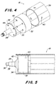
- the shaft 28 is in this embodiment as well Shaft stub formed and has the threaded end 36 and the Cone 38 on. However, the shaft 28 runs in a second Flange 42 out of clarity because of less Diameter is shown, but also the same diameter as the flange 30 can have.
- This second flange 42 is as Screw flange formed and contains a plurality of bores 44, which are suitable for receiving screws, not shown.
- the flange 30 in the manner of a simple and flat radial Disc is integrally formed with the sleeve 32 and z. B. made in one pour.
- the sleeve 32 corresponds in their Dimensions of the sleeve 32 from Figures 2 and 3 and can in in the same way in the region of the holes 40 with the tube 34 be welded if appropriate.
- the flange 30 has threaded bores 46, the arrangement of which matches that of Bores 44 covers and which are suitable by the Bores to hold 44 inserted screws.
- the shaft 28 with their second flange 42 forms in assembly with the flange 30 and the sleeve 32 a rotationally symmetrical part, the inserted concentrically into the tube 34 and in this can be set.
- the flange 30 also welded to the sleeve 32 and finally to the second flange 42 are screwed.
Landscapes
- Life Sciences & Earth Sciences (AREA)
- Environmental Sciences (AREA)
- Rolls And Other Rotary Bodies (AREA)
Description
Die Erfindung betrifft eine Rolle einer Rundballenpresse, mit einem zylindrischen Rohr, einem Wellenstummel, einem Flansch und einer Hülse.The invention relates to a roll of a round baler, with a cylindrical tube, a stub shaft, a flange and a sleeve.
Herkömmliche Rollen von Rundballenpressen enthalten ein zylindrisches und normalerweise profiliertes Stahlrohr, das sich über eine Länge von 1,2 oder 1,5 Meter erstreckt. Zur drehbaren Lagerung wird das Rohr von einer durchgehenden Welle getragen, zwischen der und dem Rohr sich mehrere Stahlblechflansche erstrecken (GREENLAND, Presse a Balles Rondes, Druckvermerk F606 1-f; CLAAS Rollant 66, Rollant 46, Druckvermerk 8/89 (Gi) ft.450/190 469.1).Conventional rolls of round balers contain one cylindrical and normally profiled steel tube, the extends over a length of 1.2 or 1.5 meters. For The pipe is rotatably supported by a continuous shaft worn, between which and the tube there are several Extend sheet steel flanges (GREENLAND, Presse a Balles Rondes, imprint F606 1-f; CLAAS Rollant 66, Rollant 46, Printed notice 8/89 (Gi) ft.450 / 190 469.1).
Aus der US-A-4,198,804 geht eine Rundballenpresse mit einer Vielzahl von Rollen hervor, die einen Ballenpreßraum umgeben und sich aus einem Rohr mit einer Vielzahl von inneren radial verlaufenden und damit verschweißten Stegen zusammensetzen. Auf jeder Seite erstreckt sich ein Wellenstummel durch die jeweiligen beiden äußeren Stege und stützt sich mittels angeschweißter Flanschbleche an dem äußeren Steg und mittels eines freien Endbereichs an dem zweiten Steg ab.From US-A-4,198,804 a round baler with a Variety of roles that surround a baling room and made up of a tube with a variety of inner radial Assemble running and welded webs. On a wave stub extends through each side respective two outer webs and is supported by means of welded flange plates on the outer web and by means of a free end area on the second web.
Dieser Aufbau ist nachteilig, weil jede Schweißverbindung zu Rissen bei den einer Dauerwechselbelastung unterworfenen Rohren führen kann und weil die erforderlichen Schweißverbindungen an den Flanschen und Rohren aufwendig sind.This construction is disadvantageous because of any welded connection Cracks in the pipes subjected to continuous alternating stress can lead and because the necessary welded connections the flanges and pipes are complex.
Das der Erfindung zugrunde liegende Problem wird darin gesehen, daß der Fertigungsaufwand zum Erreichen einer ausreichenden Biegefestigkeit relativ hoch ist und durchgehende Wellen, die im Rolleninnern mit Flanschen verbunden sind, schwierig zu montieren und demontieren sind. The problem underlying the invention is seen in that the manufacturing effort to achieve sufficient Flexural strength is relatively high and through waves that are connected to flanges inside the roller, difficult to assemble and disassemble.
Dieses Problem wird erfindungsgemäß durch die Lehre des Patentanspruchs 1 gelöst, wobei in den weiteren Patentansprüchen Merkmale aufgeführt sind, die die Lösung in vorteilhafter Weise weiterentwickeln.This problem is solved according to the invention by the teaching of the patent claim 1 solved, wherein in the further claims Features are listed that are the solution in an advantageous manner develop.
Auf diese Weise werden die Biegekräfte von der Hülse aufgenommen und in den Flansch und in die Welle bzw. den Wellenstummel eingeleitet. Bisher übliche Flansche im Rohrinnern entfallen, wodurch sich die Wartung und Herstellung vereinfacht und die Gefahr von Rissen an den Verbindungsstellen zwischen den Flanschen und dem Rohr entfällt. Eine solche Hülse kann in einfacher Weise von außen in das Rohr eingeschoben werden und bedarf bei ausreichend geringen Passungen keine stofförmigen Verbindung zwischen der Hülse und dem Rohr. Es ist nicht erforderlich, daß die Hülse mit ihrer gesamten Mantelfläche in Berührung mit der Innenfläche des Rohrs gelangt. Vielmehr reicht es aus, wenn bei einem mehrkantigen Rohr nur die inneren Kanten oder Flächen, die den inneren Umfangskreis bilden, mit der Hülse in Berührung kommen. Wichtig ist lediglich, daß sich das Rohr ausreichend fest auf der Hülse abstützt und die Biegekräfte einleiten kann. In einfacher Weise kann also eine im Querschnitt runde Hülse in ein mehrkantiges Rohr eingefügt werden. Bei engen Toleranzen kann auch eine Preßpassung durch Aufschrumpfen gewählt werden. Die übrigen Torsions- und Biegekräfte werden von der drehfesten Verbindung zwischen dem Flansch und dem Rohr aufgenommen.In this way, the bending forces from the sleeve recorded and in the flange and in the shaft or Wave stub initiated. Previously common flanges in The interior of the pipe is eliminated, which makes maintenance and production easier simplified and the risk of cracks at the joints between the flanges and the pipe. Such a sleeve can be easily inserted into the tube from the outside are and do not need with sufficiently small fits material connection between the sleeve and the tube. It is not required that the sleeve with its entire Lateral surface in contact with the inner surface of the tube reached. Rather, it is sufficient if a polygon Pipe only the inner edges or surfaces that the inner Form the circumferential circle, come into contact with the sleeve. Important is only that the tube is sufficiently tight on the sleeve supports and can initiate the bending forces. In a simple way can therefore a sleeve with a round cross-section into a polygonal Tube are inserted. With narrow tolerances, one can Press fit can be selected by shrinking on. The remaining Torsional and bending forces are exerted by the non-rotatable connection added between the flange and the pipe.
Eine leicht herstellbare Variante der Erfindung ist darin zu sehen, daß die Hülse und der Flansch in der Art eines Topfes ausgebildet sind, d. h. daß die Hülse einerseits - nicht notwendigerweise einenends - mit einer den Flansch bildenden Wandung geschlossen ist, an die/den drehfest die Welle oder der Wellenstummel angeschlossen werden kann. Die Verbindung mit der Welle oder dem Wellenstummel kann reib- oder formschlüssig erfolgen, z. B. mittels einer Verzahnung zwischen einer Nabe und der Welle oder dem Wellenstummel.An easily producible variant of the invention is included therein see that the sleeve and the flange in the manner of a pot are trained, d. H. that the sleeve on the one hand - not necessarily at one end - with one that forms the flange Wall is closed to which the shaft or the rotationally fixed Stub shaft can be connected. The connection with the Shaft or the stub shaft can be frictional or positive take place, e.g. B. by means of a toothing between a hub and the wave or the wave stub.
Eine hervorragende Wartungsmöglichkeit ergibt sich, wenn die Wellenstummel mittels eigener Flansche an den Flansch der Hülse angeschraubt werden können. Auf diese Weise braucht zum Demontieren der Rolle keine Welle entfernt zu werden, sondern es reicht aus, wenn die Wellenstummel mit ihren Flanschen demontiert werden und dann in ihren Lagern verharren können.An excellent maintenance option arises if the Shaft stub with its own flanges on the flange of the sleeve can be screwed on. That way you need to Disassembly of the roll not a shaft to be removed, but it is sufficient if the stub waves with their flanges can be dismantled and then remain in their bearings.
Eine hohe Torsions- und Biegesteifigkeit des Wellenstummels mit dem Flansch wird erreicht, wenn diese einstückig und insbesondere als Schmiedeteil ausgebildet sind. Andererseits kann dieser Teil auch aus einem hochfesten Guß gegossen werden.A high torsional and bending stiffness of the shaft end with the flange is reached if it is in one piece and are designed in particular as a forged part. On the other hand this part can also be cast from a high-strength cast.
Nach einer anderen Variante werden der Flansch und die Hülse zunächst einzeln hergestellt und dann zusammengefügt, z. B. zusammengeschweißt.According to another variant, the flange and the sleeve first manufactured individually and then assembled, e.g. B. welded together.
Zur Übertragung der Drehkräfte und zur Lagesicherung der Hülse in dem Rohr - wenn dies jeweils erforderlich ist - kann anstatt einer reibschlüssigen Schrumpfverbindung auch eine Schweißverbindung erzeugt werden, und zwar durch Punktschweißen oder durch das Anbringen von Löchern in dem Rohr, in deren Wandungsbereich das Rohr mit der Hülse verschweißt wird.For transmission of the torque and for securing the position of the sleeve in the tube - if this is necessary - can instead a frictional shrink connection also one Welded connection are generated, namely by spot welding or by making holes in the tube in their Wall area, the tube is welded to the sleeve.
Um die erfindungsgemäßen Vorteile bei optimalem Materialeinsatz zu erreichen, sollte die Hülse so bemessen sein, daß sie sich bis zu einer Stelle in dem Rohr erstreckt, an der das Rohr die maximal zu erwartende Biegebelastung ohne die Hülse aufzunehmen vermag. Diese Stelle kann rechnerisch leicht ermittelt werden, indem der Biegemomentverlauf des Rohrs bei der zu erwartenden Last ermittelt wird.To the advantages of the invention with optimal use of materials to reach, the sleeve should be dimensioned so that it extends to a point in the pipe where the pipe the maximum expected bending load without taking up the sleeve can This position can easily be determined by calculation, by the bending moment curve of the pipe at the expected Load is determined.
In der Zeichnung sind zwei nachfolgend näher beschriebene Ausführungsbeispiele der Erfindung dargestellt. Es zeigt:
- Fig. 1
- eine Rundballenpresse mit erfindungsgemäßen Rollen,
- Fig. 2
- eine erfindungsgemäße Rolle mit einer Hülse und einem getrennt von dieser hergestellten Flansch in perspektivischer Darstellung,
- Fig. 3
- die Rolle aus Figur 2 im vertikalen Längsmittenschnitt,
- Fig. 4
- eine erfindungsgemäße Rolle mit einer Hülse und einem einstückig mit dieser hergestellten Flansch in perspektivischer Darstellung, und
- Fig. 5
- die Rolle aus Figur 4 im vertikalen Längsmittenschnitt.
- Fig. 1
- a round baler with rollers according to the invention,
- Fig. 2
- a roller according to the invention with a sleeve and a flange made separately from this in a perspective view,
- Fig. 3
- the roll from Figure 2 in the vertical longitudinal center section,
- Fig. 4
- a roller according to the invention with a sleeve and a flange made in one piece with this in a perspective view, and
- Fig. 5
- the roll of Figure 4 in the vertical longitudinal center section.
Eine in Figur 1 gezeigte Rundballenpresse 10
besitzt einen Rahmen 12, der sich über Räder 14 auf dem Boden
abstützt, mittels einer Deichsel 16 an ein nicht gezeigtes
Zugfahrzeug angehängt werden kann und Rollen 18, die einen
Ballenpreßraum 20 umgeben. A
Bei der dargestellten Rundballenpresse 10 handelt
es sich um eine Rundballenpresse mit einem Ballenpreßraum 20
unveränderlicher Größe, dem über eine Aufnahmevorrichtung 22
auf dem Boden liegendes Erntegut für einen Preßvorgang
zugeführt wird.In the
Allerdings kann es sich bei der Rundballenpresse
10 auch um eine anderer Bauart handeln, z. B. um eine
Rundballenpresse mit größenveränderlichem Preßraum.However, it can be the case with the
Der Rahmen 12 enthält zwei Seitenwände 24, in denen sich eine
Vielzahl nahezu auf einem Kreis gelegener Öffnungen 26
befindet. Die Seitenwände 24 bilden die seitliche Begrenzung
des Ballenpreßraums 20.The
Die Rollen 18 sind in diesem Ausführungsbeispiel als kantige
Rotationszylinder ausgebildet und mittels nicht näher gezeigter
Lager in den Seitenwänden 24 drehbar gelagert. Je nach der
gewählten Bauart sind die Rollen 18 frei drehbar oder
angetrieben. Die Rollen 18 umgeben den Ballenpreßraum 20
umfangsseitig und werden somit ständig von dem zu pressenden
Gut beaufschlagt. Für andere Einsatzzwecke können die Rollen 18
auch im Querschnitt rund sein.The
Gemäß Figur 2 setzt sich eine Rolle 18 aus einer Welle 28 oder
Wellenstummel, einem Flansch 30, einer Hülse 32 und einem Rohr
34 zusammen.According to FIG. 2, a
Die Welle 28 ist mit einem Gewindeende 36 und einem daran
anschließenden Konus 38 versehen, die gemeinsam dazu dienen,
ein nicht gezeigtes Antriebsrad drehfest zu halten. Die Welle
28 verläuft konzentrisch zu der Rolle 18 und außerhalb des
Rohrs 34.The
Der Flansch 30 stellt sich im wesentlichen als eine radial
verlaufende Scheibe dar, deren Außendurchmesser abgesehen von
Toleranzen dem Innendurchmesser des Rohrs 34 entspricht. The
Die Welle 28 geht mit sich stets vergrößerndem Durchmesser in
den Flansch 30 über und bildet mit diesem eine stoffliche
Einheit, die aus schweißbarem Metall besteht.The
Es wäre allerdings auch möglich, die Welle 28 lösbar mit dem
Flansch 30 zu verbinden, z. B. sie in den Flansch 30
einzuschrauben oder sonstwie darin zu befestigen.However, it would also be possible to detach the
Die Hülse 32 ist von einfacher Form mit einem Außendurchmesser,
der dem Innenkreis des Rohrs 34 entspricht. Die Stärke und
Länge der Hülse 32 sind so bemessen, daß sie geeignet ist, die
auf das Rohr 34 einwirkenden Lastspitzen aufzufangen, so daß
diese die einwirkenden Biege- und gegebenenfalls
Torsionsmomente ohne Beschädigung aufnehmen kann. In einem
tatsächlichen Fall ist die Hülse 32 110 mm lang, 10 mm stark
und hat einen Außendurchmesser von 200 mm. Die Hülse 32 besteht
aus einem Metall, das mit dem des Flansches 30 verschweißt
werden kann. Der Außendurchmesser der Hülse 32 ist so zu
bemessen, daß die Hülse 32 ohne Spiel in dem Rohr 34 gehalten
wird. Gegebenenfalls kann die Hülse 32 in das Rohr 34
eingeschrumpft werden. Die Hülse 32 ist mit rundem Querschnitt
dargestellt, kann aber auch jedem Innenprofil des Rohrs 34
folgen.The
Das Rohr 34 ist als Zylinder ausgebildet, der sieben
gleichmäßig verteilte Kanten aufweist. Die Innenform des Rohrs
34 kann der Außenform der Hülse 32 entsprechen oder auch nur
stellenweise auf der Hülse 32 aufsitzen. Z. B. kann ein Rohr 34
mit mehreren Kanten und dazwischenliegenden geraden Flächen nur
im Mittenbereich der geraden Flächen auf der Hülse 32 aufsitzen
und dort mit ihr verbunden werden. Die Länge des Rohrs 34
entspricht ca. dem elf- bis fünfzehnfachen der Länge der Hülse
32. Das Rohr 34 ist vorzugsweise aus Stahl hergestellt und kann
bei Bedarf mit der Hülse 32 und/oder dem Flansch 30 verschweißt
werden. Für eine Schweißverbindung sind in die Mantelfläche in
dem Deckungsbereich mit der Hülse 32 mehrere gleichmäßig auf
dem Umfang verteilte Löcher 40 vorgesehen, deren Umfangswand
mit der Hülse 32 verschweißt werden kann.The
Der Zusammenbau der Rolle 18 wird im folgenden anhand von Figur
3 beschrieben.The assembly of the
Der Flansch 30 und die Hülse 32 werden miteinander verschweißt
und bilden eine topfartige Einheit mit einem gleichmäßigen
Außendurchmesser. Da auch die Welle 28 bzw. der Wellenstummel
drehfest mit dem Flansch 30 verbunden ist ergibt sich eine
Rotationseinheit, die in das Innere des Rohrs 34 eingeschoben
und mit diesem drehfest verbunden, z. B. verschweißt werden
kann. Wie es sich aus Figur 3 ergibt, wahrt der Flansch 30 zu
der Stirnseite des Rohrs 34 einen geringen Abstand von ca. 30 -
40 Millimeter, was jedoch keinesfalls zwingend ist.The
Im weiteren wird auf die Variante der Rolle 18 gemäß den
Figuren 4 und 5 Bezug genommen.Furthermore, the variant of the
Die Welle 28 ist auch in diesem Ausführungsbeispiel als ein
Wellenstummel ausgebildet und weist das Gewindeende 36 und den
Konus 38 auf. Allerdings läuft die Welle 28 in einem zweiten
Flansch 42 aus, der der Anschaulichkeit wegen von geringerem
Durchmesser gezeigt ist, aber auch den gleichen Durchmesser wie
der Flansch 30 haben kann. Dieser zweite Flansch 42 ist als
Schraubflansch ausgebildet und enthält mehrere Bohrungen 44,
die zur Aufnahme von nicht gezeigten Schrauben geeignet sind.The
Der Flansch 30 in der Art einer einfachen und ebenen radialen
Scheibe ist einstückig mit der Hülse 32 ausgebildet und z. B.
in einem Guß hergestellt. Die Hülse 32 entspricht in ihren
Abmessungen der Hülse 32 aus den Figuren 2 und 3 und kann in
gleicher Weise im Bereich der Löcher 40 mit dem Rohr 34
verschweißt werden, wenn dies angebracht ist. Der Flansch 30
weist Gewindebohrungen 46 auf, deren Anordnung sich mit der der
Bohrungen 44 deckt und die geeignet sind, die durch die
Bohrungen 44 gesteckten Schrauben zu halten. Die Welle 28 mit
ihrem zweiten Flansch 42 bildet im Zusammenbau mit dem Flansch
30 und der Hülse 32 einen rotationssymmetrischen Teil, der
konzentrisch in das Rohr 34 eingeschoben und in diesem
festgelegt werden kann.The
Abweichend von der vorherigen Beschreibung kann der Flansch 30
auch mit der Hülse 32 verschweißt und abschließend mit dem
zweiten Flansch 42 verschraubt werden.In deviation from the previous description, the
Claims (8)
- Roller (18) of a round baler (10), with a cylindrical tube (34), a stub shaft (28), a flange (30) and a sleeve (32), wherein:a) the sleeve (32)aa) is connected to or can be connected to the flange (30), rotationally fast therewith, into a bell-shaped unitab) has its peripheral surface lying at least partially against the inner circumference of the tube (34) over a part of the length thereof,ac) can be connected frictionally or integrally to the tube (34)ad) is dimensioned in its length in accordance with the size of the bending and torsion moments acting on the tube (34), andb) the stub shaft (28)ba) can be brought into a rotationally fast connection with the sleeve (32) andbb) is or can be attached cantilevered from the flange (30).
- A roller according to claim 1, characterized in that flange (30) and the sleeve (32) are formed in one piece, especially as a cast part, and can be connected to the stub shaft (28), rotationally fast therewith.
- A roller according to claim 2, characterized in that the stub shaft (28) is provided with a second flange (42), which can be screwed to the flange (30) of the sleeve (32).
- A roller according to claim 1, characterized in that the flange (30) is formed in one piece with the stub shaft (28), especially as a forged part, and can be connected to the sleeve (32), rotationally fast therewith.
- A roller according to claim 4, characterized in that the flange (30) and the sleeve (32) are formed in one piece as a welded assembly.
- A roller according to one or more of the preceding claims, characterized in that the flange (30) is welded to the tube (34),
- A roller according to one or more of the preceding claims, characterized in that the sleeve (32) is welded to the tube.
- A roller according to one or more of the preceding claims, characterized in that the sleeve (32) extends up to a point in the tube (34) at which the tube (34) is liable to receive the maximum anticipated bending stress without the sleeve (32).
Applications Claiming Priority (2)
| Application Number | Priority Date | Filing Date | Title |
|---|---|---|---|
| DE19801528A DE19801528B4 (en) | 1998-01-16 | 1998-01-16 | Roll of a round baler |
| DE19801528 | 1998-01-16 |
Publications (2)
| Publication Number | Publication Date |
|---|---|
| EP0931448A1 EP0931448A1 (en) | 1999-07-28 |
| EP0931448B1 true EP0931448B1 (en) | 2001-10-04 |
Family
ID=7854836
Family Applications (1)
| Application Number | Title | Priority Date | Filing Date |
|---|---|---|---|
| EP98123353A Expired - Lifetime EP0931448B1 (en) | 1998-01-16 | 1998-12-08 | Roll for rotobaler |
Country Status (4)
| Country | Link |
|---|---|
| US (1) | US6293894B2 (en) |
| EP (1) | EP0931448B1 (en) |
| CA (1) | CA2257473C (en) |
| DE (2) | DE19801528B4 (en) |
Families Citing this family (6)
| Publication number | Priority date | Publication date | Assignee | Title |
|---|---|---|---|---|
| US6676582B1 (en) * | 2000-01-07 | 2004-01-13 | Ashbrook Corporation | Belt pressure roller |
| DE10162313B4 (en) * | 2001-12-19 | 2018-10-11 | Trützschler GmbH & Co Kommanditgesellschaft | Roller for spinning preparation machine, e.g. Drum, taker or the like, for a card |
| JP2003251782A (en) * | 2002-03-06 | 2003-09-09 | Fuji Photo Film Co Ltd | Rotary drum |
| DE102006056048A1 (en) | 2006-11-28 | 2008-06-05 | Deere & Company, Moline | Roller and agricultural machine |
| GB2529381A (en) * | 2014-06-20 | 2016-02-24 | Kuhn Geldrop Bv | Baler apparatus |
| EP3289855B1 (en) * | 2016-09-04 | 2023-07-05 | CNH Industrial Belgium nv | Spread roll cap system |
Citations (1)
| Publication number | Priority date | Publication date | Assignee | Title |
|---|---|---|---|---|
| US4198804A (en) * | 1978-08-08 | 1980-04-22 | Gebr. Claas Maschinenfabrik Gmbh | Round baler machine |
Family Cites Families (16)
| Publication number | Priority date | Publication date | Assignee | Title |
|---|---|---|---|---|
| US2152076A (en) * | 1936-07-15 | 1939-03-28 | Michiana Products Corp | High temperature shaft or roll |
| US2513515A (en) * | 1946-05-13 | 1950-07-04 | Republic Steel Corp | Composite roll for electrotinplating lines |
| US2988803A (en) * | 1957-12-21 | 1961-06-20 | Heraeus Schott Quarzschmelze | Feed roller for rolling mill |
| NL251128A (en) * | 1959-09-22 | |||
| US4229950A (en) * | 1979-03-02 | 1980-10-28 | Eastman Kodak Company | Coupling for end gudgeon and internally heated roller |
| DE3304076A1 (en) * | 1983-02-07 | 1984-08-09 | Schwäbische Hüttenwerke GmbH, 7080 Aalen | LARGE DIMENSION ROLLER FOR MACHINES FOR THE PRODUCTION OF CONTINUOUS RAILWAY MATERIAL |
| DE3320715A1 (en) | 1983-06-08 | 1984-12-13 | Klöckner-Humboldt-Deutz AG Zweigniederlassung Fahr, 7702 Gottmadingen | ROUND BALE PRESS |
| DE3409713A1 (en) | 1984-03-16 | 1985-09-19 | Claas Ohg, 4834 Harsewinkel | DRIVABLE BIG PRESS |
| DE8804590U1 (en) * | 1988-04-07 | 1988-06-01 | Claas Ohg, 4834 Harsewinkel, De | |
| US4850183A (en) * | 1988-05-02 | 1989-07-25 | Fox Martin L | Crop conditioner |
| US5137196A (en) * | 1989-06-23 | 1992-08-11 | Deere & Company | Manner of rotatably mounting a bale wrapping material spreader roll to support walls |
| US5195402A (en) | 1991-01-31 | 1993-03-23 | Vermeer Manufacturing Company | Direct drive system for a baler |
| GB9123666D0 (en) * | 1991-11-07 | 1992-01-02 | British Steel Plc | Cooling of rollers |
| US5193450A (en) | 1991-12-20 | 1993-03-16 | Hay & Forage Industries | Residue reducing belt roller construction for round balers |
| US5411462A (en) * | 1993-08-30 | 1995-05-02 | Link; Terry G. | Lightweight ink transfer roll |
| US5613931A (en) * | 1994-12-19 | 1997-03-25 | Xerox Corporation | Segmented end bell |
-
1998
- 1998-01-16 DE DE19801528A patent/DE19801528B4/en not_active Expired - Fee Related
- 1998-12-08 EP EP98123353A patent/EP0931448B1/en not_active Expired - Lifetime
- 1998-12-08 DE DE59801627T patent/DE59801627D1/en not_active Expired - Lifetime
-
1999
- 1999-01-15 CA CA002257473A patent/CA2257473C/en not_active Expired - Fee Related
- 1999-01-15 US US09/232,428 patent/US6293894B2/en not_active Expired - Lifetime
Patent Citations (1)
| Publication number | Priority date | Publication date | Assignee | Title |
|---|---|---|---|---|
| US4198804A (en) * | 1978-08-08 | 1980-04-22 | Gebr. Claas Maschinenfabrik Gmbh | Round baler machine |
Also Published As
| Publication number | Publication date |
|---|---|
| EP0931448A1 (en) | 1999-07-28 |
| DE59801627D1 (en) | 2001-11-08 |
| CA2257473C (en) | 2002-11-19 |
| US6293894B2 (en) | 2001-09-25 |
| DE19801528A1 (en) | 1999-07-22 |
| US20010001779A1 (en) | 2001-05-24 |
| CA2257473A1 (en) | 1999-07-16 |
| DE19801528B4 (en) | 2006-02-09 |
Similar Documents
| Publication | Publication Date | Title |
|---|---|---|
| DE4209153C3 (en) | Shaft-hub connection | |
| EP1937430B1 (en) | Strand guide reel | |
| DE3915320A1 (en) | GRINDING ROLLER | |
| DE19635845C1 (en) | Calender roller with a cover made of elastic plastic | |
| EP0931448B1 (en) | Roll for rotobaler | |
| EP1269828A1 (en) | Rotor | |
| DE19907290C1 (en) | Roller for harvesting machine is formed as hollow cylinder in which spaced apart support bases aer arranged and end-side nave stubs are fixed to it, acting as rotary axes for roller | |
| DE1525213B2 (en) | RADIAL WIRE BALL BEARINGS | |
| DE2055147C3 (en) | Roller press | |
| AT407186B (en) | Helical gearboxes for driving a roller sleeve | |
| DE8115191U1 (en) | "DIFFERENTIAL GEARBOX" | |
| EP1834518B1 (en) | Support device for a roller, in particular of a round baler, and method for manufacturing such a roller | |
| DE10334515B4 (en) | Differential gear unit for vehicles | |
| DE19636052A1 (en) | Differential for use in vehicle transmissions | |
| WO2000001489A1 (en) | Device for grinding granular plant products, especially cereal grains | |
| DE19618800B4 (en) | baler | |
| DE3804225C2 (en) | ||
| DE1808322C3 (en) | Rotor for hammer crusher | |
| DE2645489C3 (en) | Crane wheel attachment | |
| EP0567750B1 (en) | Soil working machine, particularly a rotary harrow | |
| DE2344613C3 (en) | Two-roll straightening machine for round material such as bars and tubes | |
| DE1482876A1 (en) | Device for processing hay | |
| AT411721B (en) | CLAW COUPLING FOR SWIVELLY CONNECTED SHAFTS, PREFERABLY FOR DRIVE SHAFTS FROM WHEELS OF A RAYMARKING MACHINE | |
| DE2037627A1 (en) | Roller table roller with individual drive | |
| DE102012207482A1 (en) | Differential gear i.e. axle differential gear, for dividing driving power for e.g. left wheel drive train, has cross-type disks engaging with profiles, respectively, and profile axles running parallel to circulation axles of housing |
Legal Events
| Date | Code | Title | Description |
|---|---|---|---|
| PUAI | Public reference made under article 153(3) epc to a published international application that has entered the european phase |
Free format text: ORIGINAL CODE: 0009012 |
|
| AK | Designated contracting states |
Kind code of ref document: A1 Designated state(s): DE FR GB IT |
|
| AX | Request for extension of the european patent |
Free format text: AL;LT;LV;MK;RO;SI |
|
| 17P | Request for examination filed |
Effective date: 19991218 |
|
| AKX | Designation fees paid |
Free format text: DE FR GB IT |
|
| 17Q | First examination report despatched |
Effective date: 20000322 |
|
| GRAG | Despatch of communication of intention to grant |
Free format text: ORIGINAL CODE: EPIDOS AGRA |
|
| GRAG | Despatch of communication of intention to grant |
Free format text: ORIGINAL CODE: EPIDOS AGRA |
|
| GRAH | Despatch of communication of intention to grant a patent |
Free format text: ORIGINAL CODE: EPIDOS IGRA |
|
| GRAH | Despatch of communication of intention to grant a patent |
Free format text: ORIGINAL CODE: EPIDOS IGRA |
|
| GRAA | (expected) grant |
Free format text: ORIGINAL CODE: 0009210 |
|
| AK | Designated contracting states |
Kind code of ref document: B1 Designated state(s): DE FR GB IT |
|
| REF | Corresponds to: |
Ref document number: 59801627 Country of ref document: DE Date of ref document: 20011108 |
|
| REG | Reference to a national code |
Ref country code: GB Ref legal event code: IF02 |
|
| GBT | Gb: translation of ep patent filed (gb section 77(6)(a)/1977) |
Effective date: 20011217 |
|
| ET | Fr: translation filed | ||
| PLBE | No opposition filed within time limit |
Free format text: ORIGINAL CODE: 0009261 |
|
| STAA | Information on the status of an ep patent application or granted ep patent |
Free format text: STATUS: NO OPPOSITION FILED WITHIN TIME LIMIT |
|
| 26N | No opposition filed | ||
| PGFP | Annual fee paid to national office [announced via postgrant information from national office to epo] |
Ref country code: GB Payment date: 20131227 Year of fee payment: 16 |
|
| PGFP | Annual fee paid to national office [announced via postgrant information from national office to epo] |
Ref country code: FR Payment date: 20131217 Year of fee payment: 16 Ref country code: IT Payment date: 20131228 Year of fee payment: 16 |
|
| GBPC | Gb: european patent ceased through non-payment of renewal fee |
Effective date: 20141208 |
|
| REG | Reference to a national code |
Ref country code: FR Ref legal event code: ST Effective date: 20150831 |
|
| PG25 | Lapsed in a contracting state [announced via postgrant information from national office to epo] |
Ref country code: GB Free format text: LAPSE BECAUSE OF NON-PAYMENT OF DUE FEES Effective date: 20141208 |
|
| PG25 | Lapsed in a contracting state [announced via postgrant information from national office to epo] |
Ref country code: FR Free format text: LAPSE BECAUSE OF NON-PAYMENT OF DUE FEES Effective date: 20141231 |
|
| PG25 | Lapsed in a contracting state [announced via postgrant information from national office to epo] |
Ref country code: IT Free format text: LAPSE BECAUSE OF NON-PAYMENT OF DUE FEES Effective date: 20141208 |
|
| PGFP | Annual fee paid to national office [announced via postgrant information from national office to epo] |
Ref country code: DE Payment date: 20171231 Year of fee payment: 20 |
|
| REG | Reference to a national code |
Ref country code: DE Ref legal event code: R071 Ref document number: 59801627 Country of ref document: DE |