EP0931434B1 - Elektrisches strahlungsrohr,wärmegenerator und diffusor aus isolierenden und hochkonduktiven spiralförmig gewickelten bändern - Google Patents
Elektrisches strahlungsrohr,wärmegenerator und diffusor aus isolierenden und hochkonduktiven spiralförmig gewickelten bändern Download PDFInfo
- Publication number
- EP0931434B1 EP0931434B1 EP96941820A EP96941820A EP0931434B1 EP 0931434 B1 EP0931434 B1 EP 0931434B1 EP 96941820 A EP96941820 A EP 96941820A EP 96941820 A EP96941820 A EP 96941820A EP 0931434 B1 EP0931434 B1 EP 0931434B1
- Authority
- EP
- European Patent Office
- Prior art keywords
- electric
- bands
- generating
- radiating tube
- heat radiating
- Prior art date
- Legal status (The legal status is an assumption and is not a legal conclusion. Google has not performed a legal analysis and makes no representation as to the accuracy of the status listed.)
- Expired - Lifetime
Links
Images


Classifications
-
- H—ELECTRICITY
- H05—ELECTRIC TECHNIQUES NOT OTHERWISE PROVIDED FOR
- H05B—ELECTRIC HEATING; ELECTRIC LIGHT SOURCES NOT OTHERWISE PROVIDED FOR; CIRCUIT ARRANGEMENTS FOR ELECTRIC LIGHT SOURCES, IN GENERAL
- H05B3/00—Ohmic-resistance heating
- H05B3/40—Heating elements having the shape of rods or tubes
- H05B3/42—Heating elements having the shape of rods or tubes non-flexible
- H05B3/46—Heating elements having the shape of rods or tubes non-flexible heating conductor mounted on insulating base
-
- F—MECHANICAL ENGINEERING; LIGHTING; HEATING; WEAPONS; BLASTING
- F24—HEATING; RANGES; VENTILATING
- F24C—DOMESTIC STOVES OR RANGES ; DETAILS OF DOMESTIC STOVES OR RANGES, OF GENERAL APPLICATION
- F24C7/00—Stoves or ranges heated by electric energy
- F24C7/04—Stoves or ranges heated by electric energy with heat radiated directly from the heating element
- F24C7/043—Stoves
-
- H—ELECTRICITY
- H05—ELECTRIC TECHNIQUES NOT OTHERWISE PROVIDED FOR
- H05B—ELECTRIC HEATING; ELECTRIC LIGHT SOURCES NOT OTHERWISE PROVIDED FOR; CIRCUIT ARRANGEMENTS FOR ELECTRIC LIGHT SOURCES, IN GENERAL
- H05B3/00—Ohmic-resistance heating
- H05B3/10—Heating elements characterised by the composition or nature of the materials or by the arrangement of the conductor
-
- H—ELECTRICITY
- H05—ELECTRIC TECHNIQUES NOT OTHERWISE PROVIDED FOR
- H05B—ELECTRIC HEATING; ELECTRIC LIGHT SOURCES NOT OTHERWISE PROVIDED FOR; CIRCUIT ARRANGEMENTS FOR ELECTRIC LIGHT SOURCES, IN GENERAL
- H05B3/00—Ohmic-resistance heating
- H05B3/10—Heating elements characterised by the composition or nature of the materials or by the arrangement of the conductor
- H05B3/16—Heating elements characterised by the composition or nature of the materials or by the arrangement of the conductor the conductor being mounted on an insulating base
Definitions
- the invention concerns means for transforming electric current into heat and for diffusing it.
- Diffusers have therefore to be used with these resistances to adapt their temperatures to the requirements of the various appliances, possibly involving high thermal heads .
- the high temperatures in the resistances require both special supports made of heavy but fragile materials such as ceramic and the like, as well as complex structures for heat insulation.
- patent FR A 1 448 060 discloses an electrically insulating tube, very thick and consequently heavy, around which a band of closely meshed resistive metal is wound. Over this band, an electrically insulating band can be laid.
- Apparatus and processes for generating heat by electric current have been subject of previous patents by the same inventor, use as generators high conductors of electricity, extremely thin but of considerable,surface area, such as to permit diffusion of the heat immediately on production, of a low thermal leap compared with the environment, and therefore of high efficiency, inexpensive to run and to manufacture.
- the above invention discloses tubular heating elements whose composition and structure can offer exceptional advantages from the aspects of production, weight, efficiency and bulk as will be explained below.
- Subject of the invention is an electric radiating tube, generator and diffuser of heat, and a process for obtaining said tube by means of entirely or partially superimposed spirally-wound bands.
- One or more of said bands is of highly electrically conductive material with an extremely high ratio between surface area and thickness, of a constant cross section. Between said bands of highly conductive material, bands of electrically insulating material are inserted.
- At the ends of said tube are means of contact and connection for electric feed.
- Said means are joined to the electrically conducting bands.
- the spiralled bands can all be wound in the same direction or else one or some in one direction and one or some in the opposite direction.
- Width can be the same for all bands or different for some of them.
- the two sets of two or more electrically conducting bands are electrically connected at one end of the tube, while said two sets are respectivelly connected, at the other end of said tube, to two contacts for electric feed.
- the tube is formed of an electrically conducting band and of a band of insulating material.
- the electrically conducting bands are preferably of copper or aluminium.
- Structure of the tube is advantageously modular or continuous and, as the case may be, have a round or differently shaped cross section; it may be straight and of unlimited length, in sections, circular or annular.
- Said electric tube may advantageously be inserted in electric apparatus fitted to a ceiling, a wall or it may be portable and used to carry and electrically feed discharge lamps or glow lamps, to replace said lamps or be associated to them.
- said electric tube presents a diameter of 2-3 cm, a temperature of 100-200°C, a voltage of 12-220V.
- One or more units of said electric tube can advantageously be inserted in specially prepared electric equipment which may be portable, floor or table based or fixed to a wall or ceiling.
- the portable equipment has a flat base to stand on the floor or on a table, to which base one of more of said tubes can be applied at right angles.
- the portable equipment has two opposing flat plates between which the electric tubes are fixed at right angles.
- a number of such tubes can be joined axially, structurally and electrically separate, or else a tube can be made in any length to form lines of electric heating.
- Such lines of electric heating can be suspended, on wires or on other means, to roofs or in any case at certain heights from the ground. This may be very advantageous inside a greenhouse for example.
- the tubes forming lines of electric heating are advantageously placed axially inside parabolic reflectors.
- Composition of portable, floor or ceiling based heating equipment becomes possible, practically for any use whether in small rooms or in spaces of any size.
- the forms, sizes and electric feed values of the types of apparatus in which the electric generators of heat, subject of the present invention, can be placed also correspond to the supporting means for the well-known discharge or glow lamps.
- the contacts at the ends of said electric generators of heat can be formed so as to fit correctly onto the connections already present on existing pieces of equipment, or be replaced by simplified connections specifically for the electric contacts present at the ends of said electric generators of heat.
- the level of efficiency is very high partly because heat is diffused practically speaking at the time when it is produced and also because of the low thermal leap between heat generators and the environment.
- the tubes here invented permit the use of electricity for heating at an extremely low cost both because of the materials used and because of their negligible weight, as well as because of the high level of efficiency obtained.
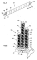
- Fig. 1 there is a tube 10 being formed on a round core 11 using four bands 20, 21,22,23 that unwind each from its own reel 25.
- the bands lie superimposed one over another by about half their width, as seen in the figure.
- Bands 20 and 22 are of electrically insulating plastic material while bands 21 and 23 are of aluminium.
- All the bands 20-23 are in fact very thin, especially those of aluminium whose thickness is measured in microns.
- the tube possesses structural continuity along its entire length and also continuous electric conduction if the ends of the aluminium bands are closed in an electric circuit.
- Closure of the electric circuit between the aluminium bands can produce electric heating, temperature and power of which can be adjusted at will by choosing suitable parameters both dimensional and in relation to the electric current supplied, especially voltage and amperage.
- the ratio between width and length of the metal bands and their thickness is similarly decisive for generation of heat, and at the same time its radiation and diffusion, in the environment with practically no need for special reflecting devices or means of support for high temperatures.
- a feature of the tube described is in fact that of diffusing heat throughout the environment practically when produced, needing no special devices.
- Fig. 2 shows an electric radiating tube 30, formed of a length of the tube 10 in Fig. 1, at whose ends two electrically insulating plastic end pieces or heads 31, 40 have been applied.
- the head 31 is applied to the tube, into one of whose ends it is fitted, having at its centre a stable connection with a U-shaped copper spring 32 whose arms 33, 34 form terminals 35, 36 and whose external shape substantially matches with the inner wall of the radiating tube 30.
- Length of the arms 33, 34 is such that, in view of the inclination of the spiral formed by the bands 20, 21, 22 and 23, contact is made between the terminal 35 and the aluminium band 21 and between terminal 36 and the band 23 also of aluminium.
- the head piece 40 fitted into the other end of the tube 30, has elastic L-shaped contacts 41, 42 respectively fixed to the head 40 by pins 43, 44.
- These elastic contacts 41, 42 are substantially identical with arms 33, 34 of the U-shaped spring 32 and the external shape of terminals 45, 46 substantially matches with the internal wall of the tubular body 30.
- inclination of the bands 20-23 and the length of said elastic contacts 41, 42 is such that contact is made between terminal 46 and the band 23 and between terminal 45 and the band 21.
- a continuous electric circuit is thus formed from pin 43 to pin 44 on the head 30, through aluminium bands 21 and 23 and the U-shaped spring on head 31.
- the tubular body 30 is turned on producing generation of heat by radiation and its diffusion.
- Fig. 3 shows an electric radiating tube 50 substantially similar to the tube 30 described above, except that it is made from only two bands.
- the band 51 is of insulating material and the band 52 of metal, especially aluminium.
- Said springs have a terminal piece 60 externally shaped to match with the internal cylindrical wall of the tubular body 50.
- an electric circuit can be closed with said tubular body so that heat is generated and diffused as in the case of radiating tube 30.
- Radiating tubes 30 and 50 therefore permit formation of electric generators, of any shape and size and for any application, capable of radiating heat.
- Fig, 4 shows a stove 70 standing on an insulating base 71 fixed to a shaped spacer 72 provided with three electric sockets, not indicated in the figure for simplicity, which sockets can receive pairs of plugs 75 from the radiating tubes 80, 81, 82 of different lengths but of the same diameter, made using four bands 20-23, substantially identical with the tubular body 30 in Figure 2.
- the stove can be connected up to main electricity by the plug 97 and switch 98.
- Fig. 5 illustrates a ready-made apparatus 100 to be ceiling mounted, built for an ordinary discharge lamp fed through the sockets 101 at each end.
- the bands, 108 of aluminium and 109 insulating, can be seen forming the tubular body 105.
- the aluminium band is electrically connected to the end head 107.
- the apparatus 110 in Figure 6 is practically the same as the one 100 already described, the only difference being that the electric sockets 111 at the ends are simplfied having only the elastic springs 112.
- Said springs 112 can make contact with the end sockets 122 on the radiating tube 120, substantially identical with the radiating tube 30 already described, except that the heads 121 are connected internally to both the metal bands.
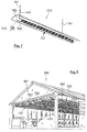
- Fig.7 shows a heating line 130 comprising a radiating tube 131 with heads 132, said line being formed of four bands, very similar to the tubular body 30 described earlier, but of considerable length supported at the two ends by sockets, like 133, applied to a parabolic channel 140 that is easily hung from the ceiling by the rods 141.
- the electric cable 145 is one of those supplying electricity.
- Fig. 8 shows how a set of heating lines 130, as described, can be used in a greenhouse 150, mounted to the ceiling 151 by rods like 152 and 153.
- this is an application of great interest as the heating lines can be extended without limits with no problems of suspension as the weight is so light, nor of varied degrees of heating, given the great versatility offered not only by electric heating but also by the tubular electric bodies subject of the invention and which are used to form said heating lines.
Landscapes
- Engineering & Computer Science (AREA)
- Chemical & Material Sciences (AREA)
- Combustion & Propulsion (AREA)
- Mechanical Engineering (AREA)
- General Engineering & Computer Science (AREA)
- Resistance Heating (AREA)
Claims (24)
- Elektrisches Strahlrohr (30, 50, 80-82, 105, 120, 131) Generator und Diffusor von Wärme
dadurch gekennzeichnet, dass es mittels Schraubenbänder (20-23, 51, 52, 108, 109), gänzlich oder teilweise überlagert, gebildet ist, wobei eines oder mehrere dieser Bänder (21, 23, 52, 108) aus hoch elektrizitätsleitendem Material besteht, mit einem sehr hohen Verhältnis zwischen der Erstreckung und der Dicke, mit konstantem Querschnitt, und wobei eines oder mehrere dieser Bänder (20,22,51,109) aus elektrischem Isolierungsmaterial sind und eingesetzt werden zwischen den Bändern (21,23,52,108) aus Material das hoch elektrizitätsleitend ist, wobei dieses Rohr (30, 50, 80-81, 105, 120, 131) an seinen Enden, mit Anschluss-und Kontaktmittel (32, 43, 44) für die Elektro-Speisung versehen ist, die an eines oder mehrere der Bänder (21,23,52,108), die hoch elektrizitätsleitend sind, verbunden sind. - Elektrisches Strahlrohr (30, 50, 80-82, 105, 120, 131) Generator und Diffusor von Wärme wie unter Anspruch 1),
dadurch gekennzeichnet, dass die Schrauben des Bandes (20-33, 51, 52) in dieselbe Richtung gewickelt sind. - Elektrisches Strahlrohr Generator und Diffusor von Wärme wie unter Anspruch 1),
dadurch gekennzeichnet, dass von den Schrauben des Bandes eine oder einige in eine Richtung, eine oder einige in die entgegengesetzte Richtung gewickelt sind. - Elektrisches Strahlrohr (30, 50, 80-82, 105, 120, 131) Generator und Diffusor von Wärme wie unter Anspruch 1),
dadurch gekennzeichnet, dass die Breiten der Bänder (20-23) gleich oder unterschiedlich sind. - Elektrisches Strahlrohr (50-105) Generator und Diffusor von Wärme wie unter Anspruch 1),
dadurch gekennzeichnet, dass es von einem elektrizitätsleitendem Band (52, 108) und von einem Band (51, 109) aus Isolierungsmaterial gebildet ist. - Elektrisches Strahlrohr (30, 80-82) Generator und Diffusor von Wärme wie unter Anspruch 1),
dadurch gekennzeichnet, dass zwei Gruppen von zwei oder mehreren elektrizitätsleitenden Bändern (21, 23) elektrisch miteinander an ein Ende des Rohres (30, 88-82) verbunden sind, während an das zweite Ende des genannten Rohres diese beiden Gruppen jeweils an zwei Kontakte (41, 42, 75) für die elektrische Speisung verbunden sind. - Elektrisches Strahlrohr (30, 50, 80-82, 105, 120, 131) Generator und Diffusor von Wärme wie unter Anspruch 1),
dadurch gekennzeichnet, dass die elektrizitätsleitenden Bänder (21, 23, 52, 108) aus Kupfer sind. - Elektrisches Strahlrohr (30, 50, 80-82, 105, 120, 131) Generator und Diffusor von Wärme wie unter Anspruch 1),
dadurch gekennzeichnet, dass die elektrizitätsleitenden Bänder (21, 23, 52, 108) aus Aluminium sind. - Elektrisches Strahlrohr (30, 50, 80-82, 105, 120, 131) Generator und Diffusor von Wärme wie unter Anspruch 1),
dadurch gekennzeichnet, dass es einen runden Schnitt aufweist. - Elektrisches Strahlrohr (30, 50, 80-82, 105, 120, 131) Generator und Diffusor von Wärme wie unter Anspruch 1),
dadurch gekennzeichnet, dass es eine gerade Entwicklung aufweist. - Elektrisches Strahlrohr Generator und Diffusor von Wärme wie unter Anspruch 1),
dadurch gekennzeichnet, dass es eine gebrochene Entwicklung aufweist. - Elektrisches Strahlrohr Generator und Diffusor von Wärme wie unter Anspruch 1),
dadurch gekennzeichnet, dass es eine kreisförmige Entwicklung aufweist. - Elektrisches Strahlrohr Generator und Diffusor von Wärme wie unter Anspruch 1),
dadurch gekennzeichnet, dass es eine ringförmige Entwicklung aufweist. - Elektrisches Strahlrohr (105) Generator und Diffusor von Wärme wie unter Anspruch 1),
dadurch gekennzeichnet, dass es in die elektrischen Deckengeräte (100), Wandgeräte oder tragbaren Handelsgeräte eingefügt wird, die für den Halter und die elektrische Speisung der sogenannten Entladungslampen als Austausch oder in Verbindung mit jenen Lampen verwendet werden. - Elektrisches Strahlrohr (120) Generator und Diffusor von Wärme wie unter Anspruch 1),
dadurch gekennzeichnet, dass die Kontakte (101) und die elektrischen Verbindungen und die Handels-Geräte (110), die als Träger und für die elektrische Speisung der sogenannten Entladungslampen verwendet werden, von den Kontakten (112) und von den elektrischen vereinfachten Verbindungen spezifisch für den Verschluss des elektrischen Kreises mit den Kontaktmitteln (121, 122) an den Enden dieses Strahlrohres (120) ersetzt werden. - Elektrisches Strahlrohr Generator und Diffusor von Wärme wie unter Anspruch 1),
durch eine Ausführungstype mit Durchmesser 2-3 cm, Temperatur 100-200°, Leistung 100-150 W, Spannung 12-220 V gekennzeichnet. - Elektrisches Strahlrohr Generator und Diffusor von Wärme wie unter Anspruch 1),
dadurch gekennzeichnet, dass es in eine oder meherere Einheiten (80-82, 105, 120, 131) in dazu vorbereitete tragbare elektrische Geräte (70) oder zur Aufstellung auf Fußböden oder auf Tische, Wände, oder Decken (100, 110, 130) eingesetzt wird. - Elektrisches Strahlrohr (80-82) Generator und Diffusor von Wärme wie unter Anspruch 17),
dadurch gekennzeichnet, dass die tragbaren Geräte (70) eine ebene Basis (71) aufweisen, die dafür geeignet ist, mit dem Fußboden oder mit der Fläche der Tische zusammenzupassen wobei an dieser Basis eines oder mehrere solcher Strahlröhre (81-82) rechtwinklig angebracht sind. - Elektrisches Strahlrohr Generator und Diffusor von Wärme wie unter Anspruch 1),
dadurch gekennzeichnet, dass die tragbaren Geräte zwei entgegengesetzte flache Platten aufweisen, zwischen denen die elektrischen Röhre rechtwinklig befestigt sind. - Elektrisches Strahlrohr (30, 50, 80-82, 105, 120, 131) Generator und Diffusor von Wärme wie unter Anspruch 1),
dadurch gekennzeichnet, dass es eine modulare Struktur aufweist. - Elektrisches Strahlrohr (131) Generator und Diffusor von Wärme wie unter Anspruch 20),
dadurch gekennzeichnet, dass eine Mehrheit an solchen Röhren axial mit Lösungen struktureller und elektrischer Kontinuität verbunden wird, wodurch elektrische Heizungslinien (130) bereitgestellt werden. - Elektrisches Strahlrohr (131) Generator und Diffusor von Wärme wie unter Anspruch 21),
dadurch gekennzeichnet, dass die Elektroheizungslinien (130) durch Schnuren (141, 152, 153) oder andere Mittel an den Dächern (151) oder jedenfalls an bestimmten Höhen vom Boden innerhalb von Gewächshäusern aufgehängt werden. - Elektrisches Strahlrohr (131) Generator und Diffusor von Wärme wie unter Anspruch 22),
dadurch gekennzeichnet, dass es axial innerhalb von parabolischen Reflektoren (140), die nach unten gerichtet sind, voreingestellt ist. - Verfahren für die Erschaffung von elektrischen Generatoren von Wärme und deren Streuung durch ein Strahlrohr (30, 50, 80-82, 105, 120, 131), das nach den Merkmalen aus den Ansprüchen 1-23 mit den Schraubenbändern (20-23, 51, 52, 108, 109), die gänzlich oder teilweise übereinandergelagert sind, erlangt wird, wobei eines oder mehrere solcher Bänder (21, 23, 52, 108) aus hoch elektrizitätsleitendem Material bestehen und mit sehr hohem Verhältnis zwischen der Erstreckung und der Dicke mit konstantem Querschnitt gestaltet sind und wobei eines oder mehrere solcher Bänder (20, 22, 51, 109) aus elektrischem Isolierungsmaterial sind und zwischen den Bändern (21, 23, 57, 108) aus hoch elektrizitätsleitendem Material eingesetzt sind und wobei ein solches Rohr (30, 50, 80-82, 105, 120, 131) an seinen Enden mit Anschluss-und Kontaktmitteln (32, 43, 44) zur Elektro-Speisung versehen ist, die an einem oder an mehreren der hoch elektrizitätsleitenden Bänder (21, 23,52, 108) angeschlossen sind.
Applications Claiming Priority (3)
| Application Number | Priority Date | Filing Date | Title |
|---|---|---|---|
| ITMI962077 | 1996-10-08 | ||
| IT96MI002077A IT1285481B1 (it) | 1996-10-08 | 1996-10-08 | Tubo radiante elettrico generatore e diffusore di calore,a nastri elicoidali,isolanti e altamente conduttori |
| PCT/IT1996/000252 WO1998016087A1 (en) | 1996-10-08 | 1996-12-16 | Electric radiating tube, generator and diffuser of heat, of insulating and of highly conducting spiralled bands |
Publications (2)
| Publication Number | Publication Date |
|---|---|
| EP0931434A1 EP0931434A1 (de) | 1999-07-28 |
| EP0931434B1 true EP0931434B1 (de) | 2001-03-28 |
Family
ID=11374998
Family Applications (1)
| Application Number | Title | Priority Date | Filing Date |
|---|---|---|---|
| EP96941820A Expired - Lifetime EP0931434B1 (de) | 1996-10-08 | 1996-12-16 | Elektrisches strahlungsrohr,wärmegenerator und diffusor aus isolierenden und hochkonduktiven spiralförmig gewickelten bändern |
Country Status (7)
| Country | Link |
|---|---|
| EP (1) | EP0931434B1 (de) |
| AT (1) | ATE200173T1 (de) |
| AU (1) | AU1109497A (de) |
| DE (1) | DE69612306D1 (de) |
| IT (1) | IT1285481B1 (de) |
| TW (1) | TW381406B (de) |
| WO (1) | WO1998016087A1 (de) |
Families Citing this family (1)
| Publication number | Priority date | Publication date | Assignee | Title |
|---|---|---|---|---|
| CN110191530B (zh) * | 2019-05-28 | 2021-10-29 | 中国电子科技集团公司第十二研究所 | 一种微波辐射加热装置 |
Family Cites Families (4)
| Publication number | Priority date | Publication date | Assignee | Title |
|---|---|---|---|---|
| DE921220C (de) * | 1941-07-05 | 1954-12-13 | Ernst Winkelmann | Heizkoerper fuer elektrische Heizgeraete |
| US2368771A (en) * | 1942-12-21 | 1945-02-06 | Mcgraw Electric Co | Encased electric heating unit and method of making same |
| FR1448060A (fr) * | 1965-04-26 | 1966-08-05 | Metal Deploye Le | Résistance électrique enroulée pour applications diverses |
| JPH0536471A (ja) * | 1991-07-31 | 1993-02-12 | Matsushita Electric Ind Co Ltd | 電気ヒーター |
-
1996
- 1996-10-08 IT IT96MI002077A patent/IT1285481B1/it active IP Right Grant
- 1996-12-16 DE DE69612306T patent/DE69612306D1/de not_active Expired - Lifetime
- 1996-12-16 AT AT96941820T patent/ATE200173T1/de active
- 1996-12-16 WO PCT/IT1996/000252 patent/WO1998016087A1/en not_active Ceased
- 1996-12-16 AU AU11094/97A patent/AU1109497A/en not_active Abandoned
- 1996-12-16 EP EP96941820A patent/EP0931434B1/de not_active Expired - Lifetime
- 1996-12-20 TW TW085115754A patent/TW381406B/zh active
Also Published As
| Publication number | Publication date |
|---|---|
| AU1109497A (en) | 1998-05-05 |
| WO1998016087A1 (en) | 1998-04-16 |
| IT1285481B1 (it) | 1998-06-08 |
| EP0931434A1 (de) | 1999-07-28 |
| ATE200173T1 (de) | 2001-04-15 |
| ITMI962077A1 (it) | 1998-04-08 |
| TW381406B (en) | 2000-02-01 |
| DE69612306D1 (de) | 2001-05-03 |
Similar Documents
| Publication | Publication Date | Title |
|---|---|---|
| US3633023A (en) | Electric lighting apparatus, particularly for decorative uses | |
| US5213519A (en) | Electrical receptacle arrangement | |
| US5440469A (en) | Low voltage track lighting fixture | |
| US4581687A (en) | Lighting means for illuminative or decorative purpose and modular lighting tube used therefor | |
| US4748545A (en) | Illumination systems | |
| US3735117A (en) | Electrified plastic christmas tree | |
| CA2088658A1 (en) | Heating element for an air flow heater | |
| TW440667B (en) | Lighting fixture with arms | |
| US7407418B1 (en) | Adapter for connecting a low voltage light bulb to a standard electrical light socket | |
| US5057978A (en) | Showcase lighting fixture | |
| EP0931434B1 (de) | Elektrisches strahlungsrohr,wärmegenerator und diffusor aus isolierenden und hochkonduktiven spiralförmig gewickelten bändern | |
| US5203626A (en) | Low voltage power distribution and lighting system | |
| US6074073A (en) | Extension device for decorative lamps | |
| US3576990A (en) | Lighting system | |
| EP1463906A1 (de) | Beleuchtungskonstruktion | |
| US3341803A (en) | Combination electrical conduit and bulb socket | |
| US5483124A (en) | Neon illumination system | |
| US2109341A (en) | Electric lighting apparatus | |
| KR101105541B1 (ko) | 적외선 전구 및 가열장치 | |
| US5174647A (en) | Modular lighting system | |
| US3729700A (en) | A universal female receiver for miniature lamp bases | |
| US1167749A (en) | Electric heating apparatus. | |
| JPH0745106A (ja) | 装飾用電球器具 | |
| US2041631A (en) | Electrical heating apparatus | |
| US1114299A (en) | Electric-light fixture. |
Legal Events
| Date | Code | Title | Description |
|---|---|---|---|
| PUAI | Public reference made under article 153(3) epc to a published international application that has entered the european phase |
Free format text: ORIGINAL CODE: 0009012 |
|
| 17P | Request for examination filed |
Effective date: 19990318 |
|
| AK | Designated contracting states |
Kind code of ref document: A1 Designated state(s): AT BE CH DE DK ES FR GB GR IE LI LU MC NL PT SE |
|
| 17Q | First examination report despatched |
Effective date: 19990722 |
|
| GRAG | Despatch of communication of intention to grant |
Free format text: ORIGINAL CODE: EPIDOS AGRA |
|
| GRAG | Despatch of communication of intention to grant |
Free format text: ORIGINAL CODE: EPIDOS AGRA |
|
| GRAH | Despatch of communication of intention to grant a patent |
Free format text: ORIGINAL CODE: EPIDOS IGRA |
|
| GRAH | Despatch of communication of intention to grant a patent |
Free format text: ORIGINAL CODE: EPIDOS IGRA |
|
| GRAA | (expected) grant |
Free format text: ORIGINAL CODE: 0009210 |
|
| AK | Designated contracting states |
Kind code of ref document: B1 Designated state(s): AT BE CH DE DK ES FR GB GR IE LI LU MC NL PT SE |
|
| PG25 | Lapsed in a contracting state [announced via postgrant information from national office to epo] |
Ref country code: NL Free format text: LAPSE BECAUSE OF FAILURE TO SUBMIT A TRANSLATION OF THE DESCRIPTION OR TO PAY THE FEE WITHIN THE PRESCRIBED TIME-LIMIT Effective date: 20010328 Ref country code: LI Free format text: LAPSE BECAUSE OF FAILURE TO SUBMIT A TRANSLATION OF THE DESCRIPTION OR TO PAY THE FEE WITHIN THE PRESCRIBED TIME-LIMIT Effective date: 20010328 Ref country code: FR Free format text: LAPSE BECAUSE OF FAILURE TO SUBMIT A TRANSLATION OF THE DESCRIPTION OR TO PAY THE FEE WITHIN THE PRESCRIBED TIME-LIMIT Effective date: 20010328 Ref country code: CH Free format text: LAPSE BECAUSE OF FAILURE TO SUBMIT A TRANSLATION OF THE DESCRIPTION OR TO PAY THE FEE WITHIN THE PRESCRIBED TIME-LIMIT Effective date: 20010328 Ref country code: BE Free format text: LAPSE BECAUSE OF FAILURE TO SUBMIT A TRANSLATION OF THE DESCRIPTION OR TO PAY THE FEE WITHIN THE PRESCRIBED TIME-LIMIT Effective date: 20010328 Ref country code: AT Free format text: LAPSE BECAUSE OF FAILURE TO SUBMIT A TRANSLATION OF THE DESCRIPTION OR TO PAY THE FEE WITHIN THE PRESCRIBED TIME-LIMIT Effective date: 20010328 |
|
| REF | Corresponds to: |
Ref document number: 200173 Country of ref document: AT Date of ref document: 20010415 Kind code of ref document: T |
|
| REG | Reference to a national code |
Ref country code: CH Ref legal event code: EP |
|
| REG | Reference to a national code |
Ref country code: IE Ref legal event code: FG4D |
|
| REF | Corresponds to: |
Ref document number: 69612306 Country of ref document: DE Date of ref document: 20010503 |
|
| PG25 | Lapsed in a contracting state [announced via postgrant information from national office to epo] |
Ref country code: SE Free format text: LAPSE BECAUSE OF FAILURE TO SUBMIT A TRANSLATION OF THE DESCRIPTION OR TO PAY THE FEE WITHIN THE PRESCRIBED TIME-LIMIT Effective date: 20010628 Ref country code: PT Free format text: LAPSE BECAUSE OF FAILURE TO SUBMIT A TRANSLATION OF THE DESCRIPTION OR TO PAY THE FEE WITHIN THE PRESCRIBED TIME-LIMIT Effective date: 20010628 Ref country code: DK Free format text: LAPSE BECAUSE OF FAILURE TO SUBMIT A TRANSLATION OF THE DESCRIPTION OR TO PAY THE FEE WITHIN THE PRESCRIBED TIME-LIMIT Effective date: 20010628 |
|
| PG25 | Lapsed in a contracting state [announced via postgrant information from national office to epo] |
Ref country code: GR Free format text: LAPSE BECAUSE OF FAILURE TO SUBMIT A TRANSLATION OF THE DESCRIPTION OR TO PAY THE FEE WITHIN THE PRESCRIBED TIME-LIMIT Effective date: 20010629 Ref country code: DE Free format text: LAPSE BECAUSE OF FAILURE TO SUBMIT A TRANSLATION OF THE DESCRIPTION OR TO PAY THE FEE WITHIN THE PRESCRIBED TIME-LIMIT Effective date: 20010629 |
|
| EN | Fr: translation not filed | ||
| NLV1 | Nl: lapsed or annulled due to failure to fulfill the requirements of art. 29p and 29m of the patents act | ||
| PG25 | Lapsed in a contracting state [announced via postgrant information from national office to epo] |
Ref country code: ES Free format text: LAPSE BECAUSE OF FAILURE TO SUBMIT A TRANSLATION OF THE DESCRIPTION OR TO PAY THE FEE WITHIN THE PRESCRIBED TIME-LIMIT Effective date: 20010927 |
|
| REG | Reference to a national code |
Ref country code: CH Ref legal event code: PL |
|
| PG25 | Lapsed in a contracting state [announced via postgrant information from national office to epo] |
Ref country code: MC Free format text: LAPSE BECAUSE OF NON-PAYMENT OF DUE FEES Effective date: 20011216 Ref country code: LU Free format text: LAPSE BECAUSE OF NON-PAYMENT OF DUE FEES Effective date: 20011216 Ref country code: GB Free format text: LAPSE BECAUSE OF NON-PAYMENT OF DUE FEES Effective date: 20011216 |
|
| PG25 | Lapsed in a contracting state [announced via postgrant information from national office to epo] |
Ref country code: IE Free format text: LAPSE BECAUSE OF FAILURE TO SUBMIT A TRANSLATION OF THE DESCRIPTION OR TO PAY THE FEE WITHIN THE PRESCRIBED TIME-LIMIT Effective date: 20011217 |
|
| REG | Reference to a national code |
Ref country code: GB Ref legal event code: IF02 |
|
| PLBE | No opposition filed within time limit |
Free format text: ORIGINAL CODE: 0009261 |
|
| STAA | Information on the status of an ep patent application or granted ep patent |
Free format text: STATUS: NO OPPOSITION FILED WITHIN TIME LIMIT |
|
| 26N | No opposition filed | ||
| GBPC | Gb: european patent ceased through non-payment of renewal fee |
Effective date: 20011216 |
|
| REG | Reference to a national code |
Ref country code: IE Ref legal event code: MM4A |