EP0931391B1 - Verbesserte synchronisation eines empfängers mit einem sender der frü und spät prüfung während grober synchronisation verwendet - Google Patents
Verbesserte synchronisation eines empfängers mit einem sender der frü und spät prüfung während grober synchronisation verwendet Download PDFInfo
- Publication number
- EP0931391B1 EP0931391B1 EP97945199A EP97945199A EP0931391B1 EP 0931391 B1 EP0931391 B1 EP 0931391B1 EP 97945199 A EP97945199 A EP 97945199A EP 97945199 A EP97945199 A EP 97945199A EP 0931391 B1 EP0931391 B1 EP 0931391B1
- Authority
- EP
- European Patent Office
- Prior art keywords
- energy
- bin
- control signal
- multiframe
- synchronization
- Prior art date
- Legal status (The legal status is an assumption and is not a legal conclusion. Google has not performed a legal analysis and makes no representation as to the accuracy of the status listed.)
- Expired - Lifetime
Links
- 238000012360 testing method Methods 0.000 title claims description 22
- 238000004891 communication Methods 0.000 claims description 89
- 238000000034 method Methods 0.000 claims description 44
- 230000005540 biological transmission Effects 0.000 claims description 17
- 230000035508 accumulation Effects 0.000 claims description 7
- 238000009825 accumulation Methods 0.000 claims description 7
- 230000010354 integration Effects 0.000 claims description 3
- 230000010267 cellular communication Effects 0.000 description 13
- 230000001413 cellular effect Effects 0.000 description 12
- 230000001360 synchronised effect Effects 0.000 description 7
- 238000001514 detection method Methods 0.000 description 6
- 238000010586 diagram Methods 0.000 description 5
- 230000003278 mimic effect Effects 0.000 description 4
- 230000008569 process Effects 0.000 description 4
- 230000006870 function Effects 0.000 description 3
- 238000012545 processing Methods 0.000 description 3
- 239000000969 carrier Substances 0.000 description 2
- 230000002452 interceptive effect Effects 0.000 description 2
- 239000000654 additive Substances 0.000 description 1
- 230000000996 additive effect Effects 0.000 description 1
- 238000004364 calculation method Methods 0.000 description 1
- 239000012141 concentrate Substances 0.000 description 1
- 230000008878 coupling Effects 0.000 description 1
- 238000010168 coupling process Methods 0.000 description 1
- 238000005859 coupling reaction Methods 0.000 description 1
- 238000002474 experimental method Methods 0.000 description 1
- 238000005259 measurement Methods 0.000 description 1
- KJLLKLRVCJAFRY-UHFFFAOYSA-N mebutizide Chemical compound ClC1=C(S(N)(=O)=O)C=C2S(=O)(=O)NC(C(C)C(C)CC)NC2=C1 KJLLKLRVCJAFRY-UHFFFAOYSA-N 0.000 description 1
- 238000010606 normalization Methods 0.000 description 1
- 238000005192 partition Methods 0.000 description 1
- 230000035945 sensitivity Effects 0.000 description 1
- 230000011664 signaling Effects 0.000 description 1
- 238000001228 spectrum Methods 0.000 description 1
- 238000012546 transfer Methods 0.000 description 1
Images


Classifications
-
- H—ELECTRICITY
- H04—ELECTRIC COMMUNICATION TECHNIQUE
- H04B—TRANSMISSION
- H04B7/00—Radio transmission systems, i.e. using radiation field
- H04B7/24—Radio transmission systems, i.e. using radiation field for communication between two or more posts
- H04B7/26—Radio transmission systems, i.e. using radiation field for communication between two or more posts at least one of which is mobile
-
- H—ELECTRICITY
- H04—ELECTRIC COMMUNICATION TECHNIQUE
- H04W—WIRELESS COMMUNICATION NETWORKS
- H04W56/00—Synchronisation arrangements
- H04W56/001—Synchronization between nodes
-
- H—ELECTRICITY
- H04—ELECTRIC COMMUNICATION TECHNIQUE
- H04L—TRANSMISSION OF DIGITAL INFORMATION, e.g. TELEGRAPHIC COMMUNICATION
- H04L7/00—Arrangements for synchronising receiver with transmitter
- H04L7/0054—Detection of the synchronisation error by features other than the received signal transition
- H04L7/007—Detection of the synchronisation error by features other than the received signal transition detection of error based on maximum signal power, e.g. peak value, maximizing autocorrelation
-
- H—ELECTRICITY
- H04—ELECTRIC COMMUNICATION TECHNIQUE
- H04L—TRANSMISSION OF DIGITAL INFORMATION, e.g. TELEGRAPHIC COMMUNICATION
- H04L7/00—Arrangements for synchronising receiver with transmitter
- H04L7/04—Speed or phase control by synchronisation signals
- H04L7/06—Speed or phase control by synchronisation signals the synchronisation signals differing from the information signals in amplitude, polarity or frequency or length
Definitions
- the present invention relates generally to synchronization methods and apparatus for synchronizing a receiver, such as a radiotelephone operable in a cellular communication system, with a transmitter which transmits signals to the receiver.
- the present invention relates to a synchronization method, and associated circuitry, in which digitally-encoded synchronization.signals are transmitted to the receiver and used by the receiver to synchronize the receiver with the transmitter.
- the present invention relates to a synchronization method, and associated circuitry, in which synchronization attempted in the presence of other high-power non-synchronization bursts is improved or made possible through use of early-late testing.
- the synchronization signals are of characteristics which permit their detection by the receiver through a correlation process of reduced complexity. Synchronization of the receiver is effectuated quickly as only a reduced number of calculations is required to detect the synchronization signals.
- the synchronization signals are of high margin to facilitate their detection by the receiver even when the signals are transmitted upon a communication channel subjected to high levels of attenuation or multi-path distortion. Because the synchronization signals are digitally-encoded, signals can be transmitted in a time division multiplex (TDM) communication scheme, such as those used in several, conventional, cellular communication systems.
- TDM time division multiplex
- the present invention is, therefore, advantageously embodied in a cellular communication system, such as a terrestrial-cellular communication system or a satellite-cellular communication system.
- a communication system is formed, at a minimum, by a transmitter and a receiver interconnected by a communication channel. Communication signals transmitted by the transmitter are transmitted upon the communication channel to be received by the receiver.
- a radio communication system is a communication system in which the communication channel is formed of one or more frequency bands of the electromagnetic frequency spectrum. Because a fixed or hard-wired connection is not required to be formed between the transmitter and the receiver, a radio communication system is advantageously utilized when the use of such fixed or hard-wired connections would be inconvenient or impractical.
- a cellular communication system is a type of radio communication system.
- the infrastructure hereinafter referred to as the network
- a subscriber to the cellular system is generally able to communicate telephonically in the system when positioned at any location in the geographical area encompassed by the system.
- terrestrial-cellular communication networks While conventional, terrestrial-cellular communication networks have been installed throughout significant portions of the world, some areas are without such networks. In areas of low population density, for instance, a terrestrial-cellular communication network might not be commercially viable. Also, existing terrestrial-cellular networks have also been constructed pursuant to various different standards.
- a radiotelephone i.e. , a hand-held or cellular telephone, operable in one of the communication systems is sometimes not operable in other such systems. Even in an area in which a cellular communication network has been installed, a user might not be able to communicate pursuant thereto if the user attempts to utilize a radiotelephone constructed to be operable only with another one of the cellular communication networks.
- Satellite-cellular communication systems such as the Association of SouthEast Asian Nations' (ASEAN) Cellular Satellite (ACeS) system which is designed to provide telephone coverage by use of a geostationary satellite
- ASEAN Association of SouthEast Asian Nations'
- ACeS Cellular Satellite
- telephonic communication shall be possible between the radiotelephone and the satellite-based transceiver.
- the user of the radiotelephone shall be able to communicate telephonically with another party by way of the ground station and the satellite-based transceiver.
- the radiotelephone To function properly, particularly when the communication system utilizes digital communication techniques, the radiotelephone must be synchronized with a network station of the cellular communication network. Conventionally, synchronization signals are transmitted by the network station to the radiotelephone to synchronize the radiotelephone with the network station.
- Other communication systems similarly utilize conventional, synchronization signals for similar purposes.
- TDMA time division multiple access
- a given frequency band is divided into a series of discrete frames each having a series of discrete timeslots therein, each timeslot for use by a different subscriber.
- ACeS provides for multiple users per time slot, effectively becoming a 16- or 32-slot system.
- information may be transmitted in burst form in accordance with a particular digital bit configuration.
- a normal burst is the transfer of speech or data information.
- burst types include high power synchronization bursts, groups of which form the aforementioned synchronization signals, which are preferably unevenly spaced across many frames within a multiframe, i.e. , 102 consecutive frames in the ACeS system.
- the initial high-power synchronization burst in such a signal is placed at the start of the first frame in a multiframe, signaling the multiframe boundary, and the remaining synchronization bursts, usually three, which could constitute high-power broadcast bursts, are unevenly spaced from the initial sync burst within the multiframe by known offsets.
- a radiotelephone or cellular phone upon initial power up, is not synchronized with the digital bit stream emanating from the transmitter and must ascertain the multiframe boundary, i.e. , the start of the initial synchronization burst, within that bit stream. Once the first sync burst and the multiframe boundary are found, the receiver may then quickly get in sync with the transmission. However, many multiframes of the transmission may transpire and a significant number of processing steps performed before synchronization is achieved even without the presence of interfering signals.
- Coarse synchronization is designed to narrow the bit stream selection to a particular portion of consecutive bits hopefully containing the initial high-power sync burst, i.e. , the multiframe boundary.
- Fine synchronization determines the exact location of the initial sync burst within that portion by correlating or matching a segment of the selected consecutive bits to a bit pattern, and shifting the segment bit by bit until correlation and synchronization are achieved.
- the focus of the present invention is to achieve faster coarse synchronization.
- high-power bursts are present in the digital bit stream which could interfere with the coarse synchronization procedure.
- high-power paging bursts may be present, particularly in an ACeS environment, to contact difficult-to-reach subscribers. The presence of these other high-powered, non-synchronization bursts in the bit stream complicates sync acquisition.
- One technique for the synchronization of a receiver with a transmitter, such as a mobile or hand-held phone of a cellular communication system, which reduces the number of processing steps, is the use of a power profile method during coarse synchronization, as will be discussed more fully later.
- the power profile technique calculates the energy accumulated in each of a plurality of bins, i.e. , subunits of a timeslot, and, through use of a priori knowledge about the spacings between high-power synchronization bursts, combines the energy accumulated in the bins to ascertain the correct multiframe boundary and thereby facilitate synchronization.
- C/N signal to noise
- noise variance is ten times signal strength, it has been found that a phone can acquire coarse synchronization within 10 multiframes using the aforedescribed power profile method. Accordingly, the time required to achieve synchronization is about 4.7 seconds (10 x 0.47 seconds per ACeS multiframe).
- a problem with the aforementioned power profile method is that it may be unable to achieve synchronization at all while other non-synchronization bursts having the same power level are transmitted on the same carrier.
- the ACeS satellite system channel power is limited and it may be difficult to page a subscriber using normal power.
- high-power paging capability may frequently be necessary, and when all the high-power bursts are on the same carrier, problems arise.
- the difficulty is that the receiver cannot distinguish between high-power synchronization (HPS) bursts and high-power paging or broadcast bursts.
- HPS high-power synchronization
- the receiver using the aforedescribed power metric, gets confused, cannot identify the multiframe boundary and, therefore, cannot synchronize.
- an object of the present invention to provide a technique for improved synchronization performance at low signal-to-noise ratios, by which coarse synchronization is achieved despite the coexistence of numerous other high-power bursts on the same control channel carrier.
- the Westinghouse reference (WO 96 12361) describes a method and apparatus for synchronizing symbol timing for a QPSK demodulator. There exists a matched filter pair that outputs "early-punctual-late" signals that are input to a symbol synchronizing estimator, which produces an interpolation control signal used by the filters to synchronize the symbol timing to the sample timing.
- These early-late signals are shown in Figure 8 and described on page 24 as having the early outputs summed, having the late outputs summed, and finding the differences between the sums. A normalization is performed by dividing the sum by the difference.
- the present invention advantageously provides an improved synchronization method, and associated circuitry, for achieving coarse synchronization of a transmitter with a receiver, such as a radiotelephone operable in a cellular communication system.
- the digitally-encoded synchronization signals are transmitted in a spaced pattern across a transmission multiframe, the first portion of which contains the start of the synchronization signal.
- the receiver synchronizes itself to these signals through the use of early-late tests, by which synchronization is possible despite the presence of non-synchronization high-power bursts from other control channels.
- an energy metric for a candidate synchronization start signal is obtained and compared with the energy metrics of related displaced previous (early) and subsequent (late) portions of the transmission signal to ascertain whether the candidate signal is indeed the synchronization signal start, marking the multiframe boundary.
- the circuitry and its associated synchronization method of the present invention are advantageously utilized in a cellular communication system to synchronize radiotelephones operable therein to a network station.
- the synchronizing signals are transmitted to the radiotelephone as portions of a control signal generated at a cellular base station.
- the synchronizing signals form portions of a control signal generated at a network control center and are transmitted to the radiotelephone by way of a satellite-based transceiver.
- the receiving apparatus utilize the early-late testing metrics of the present invention to improve synchronization accuracy, thereby reducing the time necessary for synchronization.
- a method, and associated circuitry synchronizes a receiver with a transmitter.
- the receiver and the transmitter are coupled together by way of a communication channel.
- a control signal is transmitted from the transmitter upon the communication channel.
- the control signal is formatted pursuant to a multiframe format and includes synchronization signals therein.
- the digital bit stream constituting the control signal is detected at the receiver, and a portion thereof analyzed by computing the energy accumulated therein. The aforementioned early-late tests are then computed to ascertain whether the portion is truly the start of the synchronization signal, i.e. , a multiframe boundary. If found to be the synchronization start signal, the synchronization signal and multiframe boundary are used to synchronize the receiver with the transmitter and the control signal transmitted therefrom.
- a satellite-cellular communication system shown generally at 10, includes the circuitry, and carries out the methodology, of an embodiment of the present invention. While the communication system 10 of the illustrated embodiment forms a satellite-cellular communication system, it should be understood at the outset that the circuitry and methodology of the present invention can analogously be embodied in other types of communication systems, including, for instance, a terrestrial-cellular communication system or other type of radiotelephonic communication system.
- the communication system 10 includes a ground station 12 coupled to a wireline telephonic network. Such coupling is represented in the figure by the lines 14 extending from the ground station 12.
- the ground station 12 includes transceiver circuitry for transceiving communication signals, inter alia , with a satellite-based transceiver 16.
- the satellite-based transceiver is operable to transceive communication signals not only with the ground station 12 but also with other land-based devices, such as the transceiver circuitry of a network control center 18.
- the transceiver 16 is here operable primarily as a relay station for relaying signals generated at the ground station 12 to the network control center 18 and vice-versa.
- the transceiver 16 preferably further includes control circuitry permitting the frequency channels upon which the signals transmitted to the transceiver 16, to be relayed therefrom, to be altered to most efficiently utilize the frequency channels allocated for communication in the communication system 10.
- the transceiver 22 similar to the transceiver 16 transceives communication signals with land-based transceivers including, for example, a hand-held telephone or cellular 24.
- the transceiver 22 is primarily operable to relay communication signals transmitted thereto, and again preferably includes control circuitry for selecting the frequency channels upon which signals transmitted thereto are relayed to other communication stations.
- Communication pursuant to the communication system 10 permits a user of a hand-held telephone, to communicate telephonically when positioned at any location throughout large areas of the world.
- the user of the radiotelephone 24 is positioned to permit transmission and reception of communication signals with a satellite-based transceiver, the user is able to communicate telephonically with a user of another radiotelephone or to a telephonic device of a conventional, wireline network.
- the radiotelephone 24 To operate properly, however, the radiotelephone 24 must be synchronized with the cellular network. Once properly synchronized, voice or other communications can be effectuated between the radiotelephone and the cellular network.
- Coarse synchronization between a receiver, such as the radiotelephone 24, and a transmitting station, such as the cellular network may be achieved using a linear power profile method. According to this method, a summation of discrete power samples within a plurality of bins making up a synchronization pattern is made, and through analysis of the spacings between the high-power synchronization bursts, the boundaries between the transmission multiframes are ascertained and synchronization achieved.
- a satellite communication system of which the communication system 10 of the present invention is exemplary, is, like that described in the related application, a communication system in which power signals are transmitted between the satellite of the communication system and the radiotelephone 24. Therefore, a signal to noise power ratio, C/N, is typically of a relatively low value. If an antenna at the radiotelephone is not oriented to detect the best signals transmitted thereto, the signal to noise ratio of signals actually received by the radiotelephone are even further reduced.
- paging signals are required to be transmitted at a margin of thirty decibels over average white Gaussian noise (AWGN).
- AWGN white Gaussian noise
- Such a requirement corresponds, generally, in a radiotelephone of sensitivity to detect a paging signal having a C/N ratio of about minus ten decibels.
- the communication system requires a high margin synchronization capability to allow synchronization in the presence of these other, high-power, non-synchronization signals.
- High-power synchronization (HPS) bursts transmitted to a radiotelephone permit the radiotelephone to become synchronized with the network.
- synchronization is generally a two-step process. Coarse synchronization is first effectuated; thereafter, fine synchronization is effectuated.
- coarse synchronization one or more HPS bursts during each multiframe permit synchronization of the radiotelephone to a first level of synchronization.
- acquisition to within a single symbol bit is possible; also, more precise frequency offset is provided.
- the subject matter of the present invention is concerned primarily, albeit not exclusively, with achieving coarse synchronization quickly and accurately, and despite the presence of unrelated high-power bursts within the multiframes.
- the device When the radiotelephone 24 is turned on, the device begins a coarse synchronization procedure.
- the coarse synchronization process reduces the time (and frequency) uncertainty to a selected level which in turn reduces the number of operations required to perform fine synchronization.
- the radiotelephone searches all possible primary carriers when the radiotelephone is turned on.
- a primary carrier is the carrier which multiplexes the control channels.
- the radiotelephone is assumed to have pre-registered in a region using the nominal control channels prior to receiving paging signals.
- system synchronization is effectuated by utilizing high-power synchronization (HPS) bursts which include predetermined patterns of synchronization bursts within each multiframe of the transmission.
- HPS high-power synchronization
- the bursts are time-multiplexed with other control channels and traffic channels, such as the high-powered broadcast signals on the broadcast control channel (BCCH), a paging channel or other transmission channels.
- BCCH broadcast control channel
- paging channel paging channel
- the present invention is directed to further improvements in this art, whereby synchronization is achievable despite the problem of the presence of these other interfering high-power bursts.
- each multiframe in the transmission has four high-power, unevenly spaced synchronization bursts (HPS) which are used for the initial coarse synchronization, the initial synchronization burst occurring at the multiframe boundary.
- HPS high-power synchronization bursts
- each multiframe in the ACeS system also must provide other high-power bursts on the same carrier, e.g. , high-power paging bursts (HPA) for alerting users in those areas with poor channel conditions.
- HPA high-power paging bursts
- the synchronization bursts within each multiframe may include both HPS and high-power broadcast bursts or HPB bursts on the broadcast channel (BCCH), e.g. , an HPS burst to mark the multiframe boundary and three HPB bursts, acting as HPS bursts, dispersed within the multiframe.
- BCCH broadcast channel
- the present invention seeks to solve this problem by use of an early-late test algorithm or metric which analyzes the spacing profiles of the detected high-power bursts to determine the start of the synchronization, which in turn, determines the start of a multiframe, which in turn orients the receiver to the transmitter.
- a particular portion of the detected bit stream constituting the control signal such as a bin, is selected as a hypothetical starting point, i.e. , the multiframe boundary, and the energies therein (and in the other bins within the respective timeslot) accumulated.
- the energies of those bins (and timeslots) spaced from the hypothetical bin in accordance with the known, uneven, spacing pattern for the synchronization bursts, spread across the multiframe, are also accumulated.
- the selected portion may still not be at the start of a multiframe since the aforementioned other high-power bursts could closely mimic the synchronization pattern.
- the early-late testing method of the present invention allowing synchronization in the presence of these other high-power bursts on the same channel carrier, relies upon the idea that these other high-power bursts adhere to the principle of contiguity, i.e. , the non-synchronization burst signals will be spaced apart in an even manner across the transmission stream of the control signal in accordance with the structure of bursts within a timeslot, frame and multiframe of a transmission signal. For example, one or more high-power paging signals, regularly repeating across a particular timeslot, may happen to mimic the synchronization burst spacing and an incorrect synchronization selection is made.
- bursts are contiguous, they will each bridge numerous consecutive frames within a given timeslot, e.g. , slot i of frames j, j + P, j + 2P, . . ., j + (N-1)P, where N represents the number of bursts or frames in the given message, and P represents the spacing between the bursts, i.e., the number of timeslots apart for each discrete burst, which in ACeS may be 2 or 4 due to multiple users.
- N represents the number of bursts or frames in the given message
- P represents the spacing between the bursts, i.e., the number of timeslots apart for each discrete burst, which in ACeS may be 2 or 4 due to multiple users.
- FIGURE 2 Shown in FIGURE 2 is a diagram of a multiframe MF, frames F 0 , F 23 , F 24 and F 25 within which are shown in more detail. Timeslots A 0 , A 1 , . . . A 7 within each frame F are also shown along with an expanded view of some of the timeslots showing four bins b o , b 1 , b 2 and b 3 therein, each bin containing a plurality of signal bits therein.
- a high-power paging burst is found in a given slot, e.g.
- a 6 in frame F 24 more particularly within bins b o -b 3 of that timeslot, then other bursts related to the burst in timeslot A 6 may be found in the corresponding timeslot location in other related contiguous frames, e.g. , slot A 6 in neighboring frames F 23 and F 25 , respectively transmitted just prior to and after frame F 24 .
- a paging message HPA
- the contiguous frames F 23 and F 25 may also contain other portions of the paging message.
- timeslot A 6 is the start of the paging message, then the corresponding timeslot in frame F 25 would most likely contain a subsequent portion of the page.
- Synchronization bursts are preferably spread unevenly throughout the multiframe MF in accordance with a particular pattern and on non-contiguous frames, preferably on the same timeslots within those frames. It should be understood, however, that the HPS may be on different timeslots within the respective frames. In either event, the respective synchronization burst pattern preferably does not adhere to the principle of contiguity. It should be understood, however, that the digital bit stream of control signal information detected by the receiver is an undifferentiated stream of bits, groups of which (equivalent to a bin) are selected, preferably in seriatim, for analysis. In particular, the energy accumulated in each of the respective selected portions (or bins) is computed.
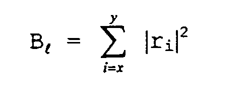
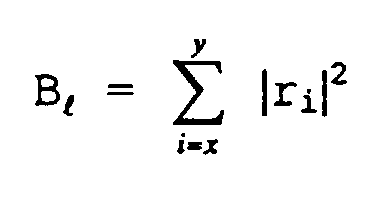
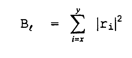
- the energy accumulated in that given bin l (B l ) is calculated by the formula: where the summation is over the received signal sample of the given bin l over the respective bits therein, i.e. , from the initial bit starting bin l, at x, to the ending bin bit, at y.
- B o , B 1 , . . . B L-1 represent the bin metrics or energies associated with bins 0, 1, . . . and L-1, respectively, where L represents the total number of bins in the multiframe MF.
- L 3,264 (102 frames/multiframe x 8 slots/frame x 4 bins/slot).
- the hypothetical starting bin i i.e. , the first bin of the first high-power synchronization burst, e.g. , bin b o in frame F 0 , timeslot A o as shown in FIGURE 2 is a correct choice for the starting synchronization burst marking the multiframe boundary.
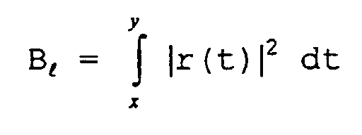
- the energy accumulated in the given bin l (B l ) may be calculated by the formula: where the integration is over the time interval of bin l, i.e. , from bit x to bit y therein, and where r is a function for the received signal sample over time over said interval.
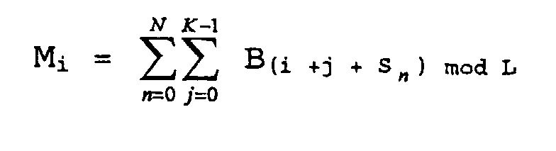
- a space-profile metric (M) for the selected bin i is calculated using the formula: where N represents the number of synchronization bursts in the multiframe MF and n is a summation counter, e.g.
- the "mod L" operation in formula (3) assures a proper wrap-around, i.e. , if the sum i+j+S n is greater than L (3,264 in ACeS), then L (or multiples thereof) is subtracted from the sum.
- bin i were the first bin of the first high-power synchronization burst, then some or all of subsequent bins in that timeslot, i.e. , bins i+1, ... I+K-1, should also have high values of B metrics.
- timeslot A 0 constituting the actual start of sync, then each of bins b o , b 1 , b 2 and b 3 within that timeslot would have high energy values therein.
- the four synchronization bursts e.g. , in timeslot A o within frames F o , F 24 , F 50 and F 75 , are spread apart unevenly in multiframe MF in an effort to distinguish the synchronization signals from other bursts.
- the metric (M) sums all of these energies to determine if the energies contained therein are high also, indicating the selection is a good candidate for the start of the synchronization signals.
- This early-late metric (D i ) compares the space profile metric M i for the hypothetical bin i with the same metric computed at P frames earlier, i.e. , M (i - KWP mod L) , and at P frames later, i.e. , M (i + KWP mod L ), using the same known synchronization burst spacings S n .
- the early-late metric (D i ) is a further check on the hypothetical selection to ascertain if a group of high-power non-synchronization bursts mimic the correct synchronization spacing in the event the hypothetical selection is incorrect.
- the space-profile metrics for the aforementioned corresponding earlier and later bins are low, then the high value of the early-late metric (D i ) for the hypothetical bin selection indicates that the selection of bin i as a part of the synchronization start signal is most likely correct. Conversely, if the early and late space-profile metrics are as high as that of M i , then the sum of the differences in equation (4) will be low, indicating that bin i may not be a suitable candidate for synchronization start and another hypothetical bin i should be selected and the above testing performed anew.
- the bit stream from the control signal is divided into a multiplicity of bin-sized portions, e.g. , at least 3,264 such portions for a 102 frame multiframe and space-profile metrics (M i ) computed for each.
- M i space-profile metrics
- the early-late metric (D i ) is then readily computed for each hypothetical bin i to ascertain the space-profile metric (and bin i) having the largest value, i.e. , the greatest differences.
- FIGURES 3 and 4 The usefulness of the early-late test metrics of the present invention in selecting a correct hypothetical bin i is illustrated in FIGURES 3 and 4. Shown in FIGURES 3A, 33 and 3C are the power level measurements over a portion of a control channel transmission signal, corresponding faded signal and corresponding received signal, respectively.
- Indicia 26a, 26b, 26c and 26d mark the positions within the respective signals of the high-power synchronization bursts in a respective multiframe, corresponding substantially to the multiframe MF shown in FIGURE 2.
- the first indicia, 26a represents an HPS burst at the multiframe boundary, i.e. , frame F o , timeslot A o , bin 0. A portion of the previous multiframe precedes indicia 26a.
- indicia 26a there follows five lower-level power bursts, representative of normal transmission power levels of, for example, the broadcast traffic channel.
- the remaining transmission in the multiframe i.e. , frames 6-101, however, illustrate a scenario where heavy paging is present with the concomitant high-power paging bursts throughout.
- the channel is, accordingly, fully loaded.
- FIGURES 3B and 3C it is shown that the HPS bursts are buried in the background. Further, since C/N is -10dB, as shown in FIGURE 3C, the noise component dominates. In other words, the variance of the noise component is ten times that of the signal component, and the multiframe boundary is indistinguishable from the noise.
- FIGURE 4A Shown in FIGURE 4A is a graph of the values of M i calculated from formula (2), the space-profile metric. Indicia 26a, representing the multiframe boundary, lost in the received control signal stream in FIGURE 3B is also lost in the space-profile values. As is clear from FIGURE 4A, the space-profile test alone cannot locate the multiframe boundary in a noisy channel, and some additional information is required to properly ascertain the multiframe boundary. In FIGURE 4B are shown the values of D i calculated from formula (3), the early-late testing metric.
- the indicia 26a for the multiframe boundary is quite prominent and readily detected, indicating that the difference metric computed in accordance with the present invention is particularly useful in acquiring synchronization despite the presence of numerous other high-power bursts in the transmission stream.
- FIGURE 5 of the drawings there is shown a block diagram of a portion of the radiotelephone 24, such as a cellular phone, which receives control signals transmitted thereto, such as from the network control center 18 through transceiver 22 shown in FIGURE 1.
- the radiotelephone 24 includes receiver circuitry 27 tunable to detect and receive signals transmitted to the radiotelephone through an antennae 28. Signals representative of the received signals are applied to a selector 30 which is operable to select portions of the in-coming received signal for analysis.
- selector 30 divides the control signal into consecutive portions which are individually processed, as described below. It should be understood, however, that selector 30 may focus the selection process, e.g. , be more responsive to high-power bursts, in an effort to concentrate the search for the initial sync burst signifying the multiframe boundary.
- the energy accumulated within the selected portions is then computed, using the nonlinear power metrics described in the aforementioned co-pending application.
- a power calculator 32 sums the energies accumulated within the respective bits within the bin. This energy sum may then be passed to an accumulator 34 which adds the new sum to previous sums, e.g. , in calculating energies contained in disparate bins using early-late tests, e.g. , the spaced-apart synchronization bursts in computing M i and the space-profile metrics at either side of the hypothetical bin i.
- the sum in accumulator 34 may then be compared with an amount stored in a memory 36 using a shift register 38, and the sum in accumulator 34 may be exchanged with that in memory 36 if a given condition is met, e.g. , the sum in accumulator 34 is greater.
- Other information about the particular bin e.g., index information, may also be stored in memory 36 to reference the particular value(s) therein.
- the aforementioned metrics M i and D i ascertain the vicinity or neighborhood of the multiframe boundary, not necessarily the exact bitwise location.
- a particular region, segment or portion within the transmitted bit stream is selected as a likely candidate, narrowing the selection to roughly a bin-sized area.
- the more cumbersome and computationally demanding fine synchronization is thereafter employed to narrow the synchronization to the bit-level.
- the division of the received control signal bit stream into bin-sized pieces may partition a transmitted timeslot and the bins therein across two received bin sample portions, thereby splitting the signal.
- the method and apparatus of the invention using the aforedescribed early-late metric is nonetheless able to ascertain the multiframe boundary quickly and reliably.
- bin metrics (B) may be computed with a greater degree of accuracy using the nonlinear techniques set forth in the present applicant's co-pending application.
- the synchronization burst pattern transmitted within each multiframe may consist of all high-power synchronization bursts, other high-power bursts, such as from the broadcast channel, may function as synchronization bursts.
- the energy accumulation technique employed in the present invention does not discern the source of the energy, merely its presence.
- the broadcast channels which typically transmit at a normal power level, as shown in FIGURES 3A and 3B, when broadcasting at full power, act as a synchronization burst.
Landscapes
- Engineering & Computer Science (AREA)
- Computer Networks & Wireless Communication (AREA)
- Signal Processing (AREA)
- Mobile Radio Communication Systems (AREA)
- Synchronisation In Digital Transmission Systems (AREA)
- Time-Division Multiplex Systems (AREA)
- Radio Relay Systems (AREA)
Claims (30)
- Verfahren zur Grobsynchronisation eines Empfängers mit einem Sender unter Verwendung eines Früh-Spät-Tests, wobei der Empfänger und der Sender mittels eines Kommunikationskanals gekoppelt sind, und das Verfahren die Schritte umfasst:Senden eines Steuersignals auf dem Kommunikationskanal aus dem Sender, wobei das Steuersignal aufgeteilt ist in eine Abfolge von aufeinanderfolgenden Multirahmen, wobei jeder Multirahmen eine Vielzahl von diskreten Rahmen umfasst und jeder der Multirahmen mindestens ein Synchronisationssignal hoher Leistung umfasst;Erfassen des Steuersignals, das während des Sendeschritts gesendet wird, beim Empfänger;Wählen zumindest eines gegebenen Abschnitts des erfassten Steuersignals;Berechnen der Energie, die innerhalb des zumindest einen gegebenen Abschnitts akkumuliert ist;Wählen mindestens eines vorangegangenen Abschnitts und mindestens eines späteren Abschnitts des erfassen Steuersignals, wobei der zumindest eine vorherige bzw. spätere Abschnitt jeweils verschoben ist, um vor bzw. nach dem zumindest einen gegebenen Abschnitt innerhalb des erfassten Steuersignals zu sein;Berechnen der Energien, die mit dem zumindest einen früheren bzw. späteren Abschnitt akkumuliert sind; undVergleichen der Energie, die innerhalb des zumindest einen gegebenen Abschnitts akkumuliert ist, mit jeweils jener des zumindest einen vorangehenden und des zumindest einen späteren Abschnitts, wobei der Vergleich zur Bestimmung einer Multirahmengrenze verwendet wird, wodurch der Empfänger mit dem Sender und dem daraus gesendeten Steuersignal grobsynchronisiert wird.
- Verfahren nach Anspruch 1, wobei der Vergleichsschritt umfasst:
Berechnen eines Differenzmaßes durch Addieren der Differenz zwischen der Energie innerhalb des zumindest einen gegebenen Abschnitts und der Energie innerhalb des zumindest einen vorangegangenen Abschnitts, und der Differenz zwischen der Energie innerhalb des zumindest einen gegebenen Abschnitts und der Energie innerhalb des zumindest einen späteren Abschnitts, wobei das Differenzmaß verwendet wird, um die Multirahmengrenze zu bestimmen. - Verfahren nach Anspruch 1, wobei das erfasste Steuersignal aufgeteilt ist in eine Vielzahl von diskreten aufeinanderfolgenden Bins, wobei das Bin i als eine Multirahmengrenze gewählt ist, die jeweiligen Abschnitte jeweils zumindest ein Bin umfassen, der Anfang des gegebenen Abschnitts das Bin i umfasst, und wobei der Berechnungsschritt ein Abstandsprofilmaß zumindest eines der Bins berechnet, in Übereinstimmung mit der Formel:wobei B die akkumulierte Energie innerhalb eines bestimmten Bins darstellt, K die Zahl der Bins innerhalb eines Zeitschlitzes darstellt, N die Zahl von diskreten Synchronisationssignalen innerhalb jedes der Multirahmen darstellt, j und n Summierungsaufzähler sind, L die Zahl der Bins innerhalb der Multirahmen darstellt, Sn die jeweiligen Abstände der N Synchronisationssignale innerhalb der Multirahmen darstellt, wobei die N Synchronisationssignale ungleichmäßig beabstandet sind innerhalb des Multirahmens und darin ein Synchronisationsmuster bilden, und Mi die Energieakkumulationen aller Bins innerhalb des Synchronisationsmusters darstellt.

- Verfahren nach Anspruch 3, wobei N im Bereich von 3 bis 8 liegt.
- Verfahren nach Anspruch 4, wobei N = 4.
- Verfahren nach Anspruch 3, wobei K = 4.
- Verfahren nach Anspruch 3, wobei S0 = 0, und S1 bis Sn ungleichmäßig beabstandet sind von S0 innerhalb des Multirahmens.
- Verfahren nach Anspruch 3, wobei der Berechnungsschritt die Energie, die innerhalb des zumindest einen vorangegangenen bzw. zumindest einen späteren Abschnitts akkumuliert ist, in Übereinstimmung mit den jeweiligen Formeln berechnet:
wobei der Schritt des Energievergleichs, der den Früh-Spät-Test verwendet, die Formel benutzt: - Verfahren nach Anspruch 3, wobei das Energiemaß für ein gegebenes Bin (Bℓ) innerhalb eines Zeitschlitzes berechnet wird unter Verwendung der Formel:wobei ri die empfangene Signalprobe darstellt, und Bℓ die akkumulierte Energie innerhalb der jeweiligen Bits von x bis y darstellt.
- Verfahren nach Anspruch 3, wobei das Energiemaß für ein gegebenes Bin (Bℓ ) innerhalb eines Zeitschlitzes berechnet wird unter Verwendung der Formel:wobei die Integration stattfindet über das Zeitintervall des Bin ℓ von Bit x zu Bit y, und r eine Funktion ist für die empfangene Signalprobe über der Zeit über das Intervall.

- In einem Kommunikationssystem, das eine erste Kommunikationsstation und eine zweite Kommunikationsstation hat, wobei die erste und zweite Kommunikationsstation mittels eines Kommunikationskanals gekoppelt sind, eine Kombination mit den ersten und zweiten Kommunikationsstationen von Schaltungen zur Synchronisierung der zweiten Kommunikationsstation mit der ersten Kommunikationsstation unter Verwendung eines Früh-Spät-Tests, wobei die Schaltungen umfassen:einen Steuersignal-Generator, der an der ersten Kommunikationsstation positioniert ist, wobei der Steuersignalgenerator dazu dient ein Steuersignal zu erzeugen und auf dem Kommunikationskanal zu senden, das gesendete Steuersignal aufgeteilt ist in eine Abfolge von aufeinanderfolgenden Multirahmen, jeder der Multirahmen eine Vielzahl von diskreten Rahmen umfasst, und jeder der Multirahmen zumindest ein Synchronisationssignal hoher Leistung umfasst;ein Steuersignaldetektor, welcher an der zweiten Kommunikationsstation positioniert ist, wobei der Steuersignaldetektor dazu dient das Steuersignal zu erfassen, das von dem Steuersignalgenerator erzeugt und gesendet wurde;einen Auswähler, der mit dem Detektor gekoppelt ist, wobei der Auswähler dazu dient zumindest einen gegebenen Abschnitt des erfassten Steuersignals zu wählen;ein Berechnungsmittel zur Akkumulierung der Energie, die akkumuliert ist innerhalb des zumindest einen gegebenen Abschnitts, und zur Akkumulierung der Energie innerhalb zumindest eines vorangegangenen Abschnitts und zumindest eines späteren Abschnitts des erfassten Steuersignals, die gegenüber dem zumindest einen gegebenen Abschnitt vorverschoben bzw. nachverschoben sind; undeinen Komparator zum Vergleichen der Energie, die innerhalb des zumindest einen gegebenen Abschnitts akkumuliert ist, mit jener des zumindest einen vorangegangenen und des zumindest einen späteren Abschnitts, wobei der Komparator verwendet wird, um eine Multirahmengrenze zu bestimmen, wodurch die zweite Kommunikationsstation mit der ersten Kommunikationsstation und dem daraus gesendeten Steuersignal grobsynchronisiert wird.
- Kommunikationssystem nach Anspruch 11, wobei das Berechnungsmittel ein Differenzmaß berechnet, durch Addition der Differenz zwischen der Energie innerhalb des zumindest einen gegebenen Abschnitts und der Energie innerhalb des zumindest einen vorangegangenen Abschnitts, und der Differenz zwischen der Energie innerhalb des zumindest einen gegebenen Abschnitts und der Energie innerhalb des zumindest einen späteren Abschnitts, wobei das Differenzmaß verwendet wird, um die Multirahmengrenze zu bestimmen.
- Kommunikationssystem nach Anspruch 11, wobei das erfasste Steuersignal aufgeteilt ist in eine Vielzahl von diskreten aufeinanderfolgenden Bins, wobei das Bin i als eine Multirahmengrenze gewählt ist, die jeweiligen Abschnitte jeweils zumindest ein Bin umfassen, der Anfang des gegebenen Abschnitts das Bin i umfasst, und wobei das Berechnungsmittel eine Abstandsprofilmetrik zumindest eines der Bins berechnet in Übereinstimmung mit der Formel:wobei B die akkumulierte Energie innerhalb eines bestimmten Bins darstellt, K die Zahl der Bins innerhalb eines Zeitschlitzes darstellt, N die Zahl der diskreten Synchronisationssignale innerhalb jedes der Multirahmen darstellt, j und n Summierungszähler sind, L die Zahl der Bins innerhalb der Multirahmen darstellt, Sn die jeweiligen Abstände der N Synchronisationssignale innerhalb der Multirahmen darstellt, wobei die N Synchronisationssignale ungleichmäßig beabstandet sind innerhalb des Multirahmens und darin in Synchronisationsmuster bilden, und Mi die Energieakkumulation aller Bins innerhalb des Synchronisationsmusters darstellt.

- Kommunikationssystem nach Anspruch 13, wobei N im Bereich von 3 bis 8 liegt.
- Kommunikationssystem nach Anspruch 14, wobei N = 4.
- Kommunikationssystem nach Anspruch 13, wobei K = 4.
- Kommunikationssystem nach Anspruch 13, wobei S0 = 0 und S1 bis Sn ungleichmäßig beabstandet sind von S0 innerhalb des Multirahmens.
- Kommunikationssystem nach Anspruch 13, wobei das Berechnungsmittel die Abstandsprofilmaße für den zumindest einen vorangegangenen und den zumindest einen späteren Abschnitt in Übereinstimmung mit den jeweiligen Formeln berechnet:
- Kommunikationssystem nach Anspruch 13, wobei das Berechnungsmittel das Bin-Energiemaß in Übereinstimmung mit der Formel berechnet:wobei ri die empfangene Signalprobe darstellt, und Bℓ die akkumulierte Energie innerhalb der jeweiligen Bits von x bis y darstellt.
- Kommunikationssystem nach Anspruch 13, wobei das Berechnungsmittel das Bin-Energiemaß in Übereinstimmung mit der Formel berechnet:wobei ri die empfangene Signalprobe darstellt, und Bℓ die akkumulierte Energie innerhalb der jeweiligen Bits von x bis y darstellt.
- Empfänger, der mit einem Sender synchronisierbar ist, umfassend:einen Steuersignal-Detektor zur Erfassung der Übertragung eines Steuersignals, wobei das Steuersignal vom Sender übertragen wird, das gesendete Steuersignal aufgeteilt ist in eine Abfolge von aufeinanderfolgenden Multirahmen, jeder der Multirahmen eine Vielzahl von diskreten Rahmen umfasst, und jeder der Multirahmen zumindest ein Synchronisationssignal hoher Leistung umfasst;einen Auswähler, der mit dem Detektor gekoppelt ist, wobei der Auswähler dazu dient zumindest einen gegebenen Abschnitt des erfassten Steuersignals zu wählen;ein Berechnungsmittel zum Messen und Akkumulieren der Energie, die akkumuliert ist innerhalb des zumindest einen gegebenen Abschnitts, und zum Akkumulieren der Energie innerhalb zumindest eines vorangegangenen Abschnitts und zumindest eine späteren Abschnitts des erfassten Steuersignals, die jeweils vorverschoben bzw. nachverschoben sind bezüglich des einen gegebenen Abschnitts; undeinen Komparator zum Vergleichen der Energie, die akkumuliert ist innerhalb des zumindest einen gegebenen Abschnitts, mit jener des zumindest einen vorangegangenen und des zumindest einen späteren Abschnitts, wobei der Komparator verwendet wird, um eine Multirahmengrenze zu bestimmen, wodurch die zweite Kommunikationsstation mit der ersten Kommunikationsstation und dem daraus gesendeten Steuersignal grobsynchronisiert wird.
- Empfänger nach Anspruch 21, wobei das Berechnungsmittel ein Differenzmaß berechnet, durch Addieren der Differenz zwischen der Energie innerhalb des zumindest einen gegebenen Abschnitts und der Energie innerhalb des zumindest einen vorangegangenen Abschnitts, und der Differenz zwischen der Energie innerhalb des zumindest einen gegebenen Abschnitts und der Energie innerhalb des zumindest einen späteren Abschnitts, wobei das Differenzmaß verwendet wird, um die Multirahmengrenze zu bestimmen.
- Empfänger nach Anspruch 21, wobei das erfasste Steuersignal aufgeteilt ist in eine Vielzahl von diskreten aufeinanderfolgenden Bins, wobei das Bin i als eine Multirahmengrenze gewählt ist, die jeweiligen Abschnitte jeweils zumindest ein Bin umfassen, der Anfang des gegebenen Abschnitts das Bin i umfasst, und wobei das Berechnungsmittel ein Abstandsprofilmaß zumindest eines der Bins in Übereinstimmung mit der Formel berechnet:wobei B die akkumulierte Energie innerhalb eines bestimmten Bins darstellt, K die Zahl von Bins innerhalb eines Zeitschlitzes darstellt, N die Zahl von diskreten Synchronisationssignalen innerhalb jeder der Multirahmen darstellt, j und n Summierungsaufzähler sind, L die Zahl von Bins innerhalb der Multirahmen darstellt, Sn die jeweiligen Abstände der N Synchronisationssignale innerhalb der Multirahmen darstellt, wobei die N Synchronisationssignale ungleichmäßig beabstandet sind innerhalb des Multirahmens und darin ein Synchronisationsmuster bilden, und Mi die Energieakkumulationen aller Bins innerhalb des Synchronisationsmusters darstellt.
- Kommunikationssystem nach Anspruch 23, wobei N eine im Bereich von 3 bis 8 liegt.
- Kommunikationssystem nach Anspruch 24, wobei N = 4.
- Kommunikationssystem nach Anspruch 23, wobei K = 4.
- Kommunikationssystem nach Anspruch 23, wobei S0 = 0 und S1 bis Sn ungleichmäßig beabstandet sind von S0 innerhalb des Multirahmens.
- Empfänger nach Anspruch 23, wobei der Berechnungsschritt die Energie, welche innerhalb des zumindest einen vorangegangenen und des zumindest einen späteren Abschnitts akkumuliert ist, in Übereinstimmung mit den Formeln berechnet:
wobei der Schritt des Energievergleichs, der den Früh-Spät-Test verwendet, die Formel verwendet: - Empfänger nach Anspruch 23, wobei das Energiemaß für ein gegebenes Bin (Bℓ) innerhalb eines Zeitschlitzes berechnet wird unter Verwendung der Formel:wobei ri die empfangene Signalprobe darstellt, und Bℓ die akkumulierte Energie innerhalb der jeweiligen Bits von x bis y darstellt.
- Empfänger nach Anspruch 23, wobei das Energiemaß für ein gegebenes Bin (Bℓ) innerhalb eines Zeitschlitzes unter Verwendung der Formel berechnet wird:wobei die Integration stattfindet über das Zeitintervall des Bins ℓ von Bit x bis Bit y, und r eine Funktion für die empfangene Signalprobe über der Zeit über das Intervall ist.

Applications Claiming Priority (3)
| Application Number | Priority Date | Filing Date | Title |
|---|---|---|---|
| US08/727,370 US5805646A (en) | 1996-10-08 | 1996-10-08 | Synchronization method, and associated circuitry, for improved synchronization of a receiver with a transmitter using early-late testing during coarse synchronization |
| US727370 | 1996-10-08 | ||
| PCT/US1997/015840 WO1998016031A2 (en) | 1996-10-08 | 1997-10-07 | Improved synchronization of a receiver with a transmitter using early-late testing during coarse synchronization |
Publications (2)
| Publication Number | Publication Date |
|---|---|
| EP0931391A2 EP0931391A2 (de) | 1999-07-28 |
| EP0931391B1 true EP0931391B1 (de) | 2000-12-13 |
Family
ID=24922380
Family Applications (1)
| Application Number | Title | Priority Date | Filing Date |
|---|---|---|---|
| EP97945199A Expired - Lifetime EP0931391B1 (de) | 1996-10-08 | 1997-10-07 | Verbesserte synchronisation eines empfängers mit einem sender der frü und spät prüfung während grober synchronisation verwendet |
Country Status (11)
| Country | Link |
|---|---|
| US (1) | US5805646A (de) |
| EP (1) | EP0931391B1 (de) |
| JP (1) | JP3783078B2 (de) |
| KR (1) | KR20000048973A (de) |
| CN (1) | CN1100414C (de) |
| AU (1) | AU725217B2 (de) |
| BR (1) | BR9711592A (de) |
| CA (1) | CA2267836A1 (de) |
| DE (1) | DE69703700T2 (de) |
| TW (1) | TW351893B (de) |
| WO (1) | WO1998016031A2 (de) |
Families Citing this family (15)
| Publication number | Priority date | Publication date | Assignee | Title |
|---|---|---|---|---|
| US5933418A (en) * | 1996-11-15 | 1999-08-03 | Ericsson Inc. | Method for increasing control channel capacity in a communication system |
| US6072786A (en) * | 1997-06-12 | 2000-06-06 | Ericsson Inc. | Method for acquisition of spotbeam beacon frequency within a satellite communications system |
| US6134283A (en) * | 1997-11-18 | 2000-10-17 | Amati Communications Corporation | Method and system for synchronizing time-division-duplexed transceivers |
| DE19814530A1 (de) * | 1998-04-01 | 1999-10-07 | Bosch Gmbh Robert | Verfahren zur digitalen Übertragung von Daten in einem drahtlosen Kommunikationsnetz und Empfangsgerät zum Empfang von nach dem Verfahren übertragenen Daten |
| US6205193B1 (en) | 1998-10-15 | 2001-03-20 | Ericsson Inc. | Systems and methods for fast terminal synchronization in a wireless communication system |
| WO2000067404A1 (de) * | 1999-04-29 | 2000-11-09 | Siemens Aktiengesellschaft | Verfahren zur bildung bzw. ermittlung einer signalfolge, verfahren zur synchronisation, sendeeinheit und empfangseinheit |
| US6823302B1 (en) | 1999-05-25 | 2004-11-23 | National Semiconductor Corporation | Real-time quality analyzer for voice and audio signals |
| KR100623214B1 (ko) * | 1999-05-25 | 2006-09-12 | 내셔널 세미컨덕터 코포레이션 | 음성 및 오디오신호의 실시간 품질 분석기 |
| EP1067705B1 (de) * | 1999-07-09 | 2009-08-26 | Sony Deutschland GmbH | Zellreichweiten-Erweiterung in Radiokommunikationssystemen mit Leistungsregelung der Abwärtsrichtung |
| US6834040B2 (en) * | 2001-02-15 | 2004-12-21 | Agilent Technologies, Inc. | Measurement synchronization method for voice over packet communication systems |
| JP3877579B2 (ja) * | 2001-11-26 | 2007-02-07 | 古野電気株式会社 | Tdma通信装置 |
| KR100613602B1 (ko) * | 2005-02-07 | 2006-08-21 | 삼성전자주식회사 | Vsb 수신기에 적용되는 심벌 타이밍 복원 장치 및 그방법 |
| US10225809B2 (en) | 2014-04-04 | 2019-03-05 | British Telecommunications Public Limited Company | Power based frame timing synchronization for a time-division duplexing network |
| CN104639274B (zh) * | 2014-12-31 | 2017-12-22 | 北京遥测技术研究所 | 一种tdma组网的多目标测控方法 |
| CN118764153B (zh) * | 2024-09-09 | 2025-01-14 | 杰创智能科技股份有限公司 | Gsm系统的复帧同步方法、装置、设备及存储介质 |
Family Cites Families (8)
| Publication number | Priority date | Publication date | Assignee | Title |
|---|---|---|---|---|
| US5228057A (en) * | 1989-11-15 | 1993-07-13 | Telefonaktiebolaget L M Ericsson | Method of determining sampling time points |
| DE59308402D1 (de) * | 1992-09-29 | 1998-05-20 | Ascom Tech Ag | Verfahren zum Synchronisieren eines Empfängers zum Empfang eines mit einem PN-Code gespreizten Datensignals |
| JP3212390B2 (ja) * | 1992-11-17 | 2001-09-25 | クラリオン株式会社 | スライディング相関器 |
| IT1256471B (it) * | 1992-12-10 | 1995-12-07 | Italtel Spa | Metodo per l'acqisizione del sincronismo tra stazione fissa e apparecchio telefonico portatile in un sistema digitale di telefonia cordless |
| US5444697A (en) * | 1993-08-11 | 1995-08-22 | The University Of British Columbia | Method and apparatus for frame synchronization in mobile OFDM data communication |
| US5768323A (en) * | 1994-10-13 | 1998-06-16 | Westinghouse Electric Corporation | Symbol synchronizer using modified early/punctual/late gate technique |
| US5646947A (en) * | 1995-03-27 | 1997-07-08 | Westinghouse Electric Corporation | Mobile telephone single channel per carrier superframe lock subsystem |
| DE19838764B4 (de) * | 1998-08-26 | 2009-01-08 | A. Raymond & Cie | Scheibenwaschdüse |
-
1996
- 1996-10-08 US US08/727,370 patent/US5805646A/en not_active Expired - Lifetime
-
1997
- 1997-09-30 TW TW086114239A patent/TW351893B/zh not_active IP Right Cessation
- 1997-10-07 DE DE69703700T patent/DE69703700T2/de not_active Expired - Lifetime
- 1997-10-07 CA CA002267836A patent/CA2267836A1/en not_active Abandoned
- 1997-10-07 EP EP97945199A patent/EP0931391B1/de not_active Expired - Lifetime
- 1997-10-07 AU AU46452/97A patent/AU725217B2/en not_active Ceased
- 1997-10-07 CN CN97180409A patent/CN1100414C/zh not_active Expired - Fee Related
- 1997-10-07 JP JP51751598A patent/JP3783078B2/ja not_active Expired - Fee Related
- 1997-10-07 KR KR1019990703022A patent/KR20000048973A/ko not_active Ceased
- 1997-10-07 BR BR9711592A patent/BR9711592A/pt unknown
- 1997-10-07 WO PCT/US1997/015840 patent/WO1998016031A2/en not_active Ceased
Also Published As
| Publication number | Publication date |
|---|---|
| US5805646A (en) | 1998-09-08 |
| EP0931391A2 (de) | 1999-07-28 |
| JP2001502134A (ja) | 2001-02-13 |
| DE69703700T2 (de) | 2001-05-10 |
| CN1100414C (zh) | 2003-01-29 |
| KR20000048973A (ko) | 2000-07-25 |
| TW351893B (en) | 1999-02-01 |
| BR9711592A (pt) | 1999-08-24 |
| AU4645297A (en) | 1998-05-05 |
| WO1998016031A2 (en) | 1998-04-16 |
| DE69703700D1 (de) | 2001-01-18 |
| WO1998016031A3 (en) | 1998-05-22 |
| AU725217B2 (en) | 2000-10-05 |
| JP3783078B2 (ja) | 2006-06-07 |
| CA2267836A1 (en) | 1998-04-16 |
| CN1240076A (zh) | 1999-12-29 |
Similar Documents
| Publication | Publication Date | Title |
|---|---|---|
| EP0891660B1 (de) | Synchronisationsverfahren und -vorrichtung zur synchronisation eines senders mit einem empfänger | |
| EP0767557B1 (de) | Verfahren zur Darstellung von Taktinformation aus einem empfangenem Signal in einem Übertragungssystem sowie Anordnung einer dieses Verfahrens anwendenden Mobilstation | |
| US4688210A (en) | Method of and arrangement for synchronizing the receiver arrangements in a digital multiplex transmission system | |
| EP0931391B1 (de) | Verbesserte synchronisation eines empfängers mit einem sender der frü und spät prüfung während grober synchronisation verwendet | |
| US5506863A (en) | Method and apparatus for operating with a hopping control channel in a communication system | |
| US5428647A (en) | Method and apparatus for synchronizing a received signal in a digital radio communication system | |
| RU2144733C1 (ru) | Пакет канала сигнализации для системы связи с опорным сигналом, модулированным по закону, зависящему от времени | |
| US6961352B2 (en) | Method of synchronizing a radio terminal of a radio communication network and a corresponding radio terminal | |
| US5907813A (en) | Signal acquisition in a wireless communication system by transmitting repeated access probes from a terminal to a hub | |
| US6577615B1 (en) | Method, mobile station and base station for frequency synchronization of a mobile station in a radio communications system | |
| CN1643964B (zh) | 用于移动无线通讯系统中压缩模式的配置方法 | |
| US5983111A (en) | Adaptive constant false alarm rate system for detecting CDPD bursts | |
| EP0931390B1 (de) | Verbesserte synchronisation eines empfängers mit einem sender der nicht lineare metrische transformationen gebraucht | |
| EP0988716B1 (de) | Verfahren zur erfassung der frequenz eines strahlenbündel-funkfeuers in einem satelliten-kommunikationssystem | |
| US20030108026A1 (en) | Power level detection for mobile communication system | |
| JPH06224872A (ja) | 同期装置 |
Legal Events
| Date | Code | Title | Description |
|---|---|---|---|
| PUAI | Public reference made under article 153(3) epc to a published international application that has entered the european phase |
Free format text: ORIGINAL CODE: 0009012 |
|
| 17P | Request for examination filed |
Effective date: 19990416 |
|
| AK | Designated contracting states |
Kind code of ref document: A2 Designated state(s): DE FR GB SE |
|
| GRAG | Despatch of communication of intention to grant |
Free format text: ORIGINAL CODE: EPIDOS AGRA |
|
| 17Q | First examination report despatched |
Effective date: 19990915 |
|
| GRAG | Despatch of communication of intention to grant |
Free format text: ORIGINAL CODE: EPIDOS AGRA |
|
| GRAH | Despatch of communication of intention to grant a patent |
Free format text: ORIGINAL CODE: EPIDOS IGRA |
|
| GRAH | Despatch of communication of intention to grant a patent |
Free format text: ORIGINAL CODE: EPIDOS IGRA |
|
| GRAA | (expected) grant |
Free format text: ORIGINAL CODE: 0009210 |
|
| AK | Designated contracting states |
Kind code of ref document: B1 Designated state(s): DE FR GB SE |
|
| REF | Corresponds to: |
Ref document number: 69703700 Country of ref document: DE Date of ref document: 20010118 |
|
| ET | Fr: translation filed | ||
| PLBE | No opposition filed within time limit |
Free format text: ORIGINAL CODE: 0009261 |
|
| STAA | Information on the status of an ep patent application or granted ep patent |
Free format text: STATUS: NO OPPOSITION FILED WITHIN TIME LIMIT |
|
| 26N | No opposition filed | ||
| REG | Reference to a national code |
Ref country code: GB Ref legal event code: IF02 |
|
| PGFP | Annual fee paid to national office [announced via postgrant information from national office to epo] |
Ref country code: SE Payment date: 20071029 Year of fee payment: 11 |
|
| EUG | Se: european patent has lapsed | ||
| PG25 | Lapsed in a contracting state [announced via postgrant information from national office to epo] |
Ref country code: SE Free format text: LAPSE BECAUSE OF NON-PAYMENT OF DUE FEES Effective date: 20081008 |
|
| REG | Reference to a national code |
Ref country code: DE Ref legal event code: R082 Ref document number: 69703700 Country of ref document: DE Representative=s name: EIP EUROPE LLP, GB Ref country code: DE Ref legal event code: R082 Ref document number: 69703700 Country of ref document: DE |
|
| REG | Reference to a national code |
Ref country code: GB Ref legal event code: 732E Free format text: REGISTERED BETWEEN 20130815 AND 20130821 |
|
| REG | Reference to a national code |
Ref country code: FR Ref legal event code: TP Owner name: UNWIRED PLANET, LLC, US Effective date: 20130919 |
|
| REG | Reference to a national code |
Ref country code: DE Ref legal event code: R081 Ref document number: 69703700 Country of ref document: DE Owner name: UNWIRED PLANET INTERNATIONAL LTD., IE Free format text: FORMER OWNER: ERICSSON INC., RESEARCH TRIANGLE PARK, N.C., US Effective date: 20130903 Ref country code: DE Ref legal event code: R081 Ref document number: 69703700 Country of ref document: DE Owner name: UNWIRED PLANET LLC, US Free format text: FORMER OWNER: ERICSSON INC., RESEARCH TRIANGLE PARK, US Effective date: 20130903 |
|
| REG | Reference to a national code |
Ref country code: GB Ref legal event code: 732E Free format text: REGISTERED BETWEEN 20131205 AND 20131211 |
|
| PGFP | Annual fee paid to national office [announced via postgrant information from national office to epo] |
Ref country code: GB Payment date: 20131021 Year of fee payment: 17 Ref country code: FR Payment date: 20131022 Year of fee payment: 17 Ref country code: DE Payment date: 20131021 Year of fee payment: 17 |
|
| REG | Reference to a national code |
Ref country code: DE Ref legal event code: R082 Ref document number: 69703700 Country of ref document: DE Representative=s name: EIP EUROPE LLP, GB |
|
| REG | Reference to a national code |
Ref country code: DE Ref legal event code: R082 Ref document number: 69703700 Country of ref document: DE Representative=s name: EIP EUROPE LLP, GB Effective date: 20140731 Ref country code: DE Ref legal event code: R082 Ref document number: 69703700 Country of ref document: DE Representative=s name: EIP EUROPE LLP, GB Effective date: 20130903 Ref country code: DE Ref legal event code: R081 Ref document number: 69703700 Country of ref document: DE Owner name: UNWIRED PLANET INTERNATIONAL LTD., IE Free format text: FORMER OWNER: UNWIRED PLANET LLC, RENO, NEV., US Effective date: 20140731 |
|
| REG | Reference to a national code |
Ref country code: FR Ref legal event code: TP Owner name: UNWIRED PLANET INTERNATIONAL LIMITED, IE Effective date: 20140903 |
|
| REG | Reference to a national code |
Ref country code: DE Ref legal event code: R119 Ref document number: 69703700 Country of ref document: DE |
|
| GBPC | Gb: european patent ceased through non-payment of renewal fee |
Effective date: 20141007 |
|
| REG | Reference to a national code |
Ref country code: GB Ref legal event code: 732E Free format text: REGISTERED BETWEEN 20150618 AND 20150624 |
|
| PG25 | Lapsed in a contracting state [announced via postgrant information from national office to epo] |
Ref country code: DE Free format text: LAPSE BECAUSE OF NON-PAYMENT OF DUE FEES Effective date: 20150501 Ref country code: GB Free format text: LAPSE BECAUSE OF NON-PAYMENT OF DUE FEES Effective date: 20141007 |
|
| REG | Reference to a national code |
Ref country code: FR Ref legal event code: ST Effective date: 20150630 |
|
| PG25 | Lapsed in a contracting state [announced via postgrant information from national office to epo] |
Ref country code: FR Free format text: LAPSE BECAUSE OF NON-PAYMENT OF DUE FEES Effective date: 20141031 |
|
| REG | Reference to a national code |
Ref country code: FR Ref legal event code: CL Name of requester: CLUSTER LLC, US Effective date: 20160922 |