EP0931258B1 - Porte-cartouche a raccord auto-ajustable, se vissant directement - Google Patents
Porte-cartouche a raccord auto-ajustable, se vissant directement Download PDFInfo
- Publication number
- EP0931258B1 EP0931258B1 EP97909939A EP97909939A EP0931258B1 EP 0931258 B1 EP0931258 B1 EP 0931258B1 EP 97909939 A EP97909939 A EP 97909939A EP 97909939 A EP97909939 A EP 97909939A EP 0931258 B1 EP0931258 B1 EP 0931258B1
- Authority
- EP
- European Patent Office
- Prior art keywords
- stem
- housing
- cavity
- cartridge
- longitudinal axis
- Prior art date
- Legal status (The legal status is an assumption and is not a legal conclusion. Google has not performed a legal analysis and makes no representation as to the accuracy of the status listed.)
- Expired - Lifetime
Links
- 238000007667 floating Methods 0.000 claims abstract description 83
- 230000033001 locomotion Effects 0.000 claims abstract description 35
- 239000012530 fluid Substances 0.000 claims description 52
- 238000004891 communication Methods 0.000 claims description 23
- 238000000034 method Methods 0.000 claims description 21
- 238000004587 chromatography analysis Methods 0.000 claims description 19
- 239000000463 material Substances 0.000 claims description 12
- 229920003023 plastic Polymers 0.000 claims description 10
- 239000004033 plastic Substances 0.000 claims description 10
- 230000000452 restraining effect Effects 0.000 claims description 10
- 238000007789 sealing Methods 0.000 claims description 7
- 229910052755 nonmetal Inorganic materials 0.000 claims description 2
- 239000002184 metal Substances 0.000 description 14
- 230000008878 coupling Effects 0.000 description 6
- 238000010168 coupling process Methods 0.000 description 6
- 238000005859 coupling reaction Methods 0.000 description 6
- 238000012856 packing Methods 0.000 description 6
- 230000008569 process Effects 0.000 description 5
- 238000013461 design Methods 0.000 description 4
- 230000000670 limiting effect Effects 0.000 description 4
- 239000012071 phase Substances 0.000 description 4
- 238000009434 installation Methods 0.000 description 3
- 238000002045 capillary electrochromatography Methods 0.000 description 2
- 238000011109 contamination Methods 0.000 description 2
- 238000001212 derivatisation Methods 0.000 description 2
- 238000001914 filtration Methods 0.000 description 2
- 238000004817 gas chromatography Methods 0.000 description 2
- 238000004128 high performance liquid chromatography Methods 0.000 description 2
- 238000004519 manufacturing process Methods 0.000 description 2
- 230000007246 mechanism Effects 0.000 description 2
- 230000004323 axial length Effects 0.000 description 1
- 238000005452 bending Methods 0.000 description 1
- 230000000593 degrading effect Effects 0.000 description 1
- 238000011161 development Methods 0.000 description 1
- 230000018109 developmental process Effects 0.000 description 1
- 239000003480 eluent Substances 0.000 description 1
- 238000012986 modification Methods 0.000 description 1
- 230000004048 modification Effects 0.000 description 1
- 238000002360 preparation method Methods 0.000 description 1
- 238000003825 pressing Methods 0.000 description 1
- 230000001681 protective effect Effects 0.000 description 1
- 230000002829 reductive effect Effects 0.000 description 1
- 238000009877 rendering Methods 0.000 description 1
- 230000000717 retained effect Effects 0.000 description 1
- 238000000926 separation method Methods 0.000 description 1
- 239000007790 solid phase Substances 0.000 description 1
- 238000004808 supercritical fluid chromatography Methods 0.000 description 1
- 210000005239 tubule Anatomy 0.000 description 1
- 238000011144 upstream manufacturing Methods 0.000 description 1
Images


Classifications
-
- B—PERFORMING OPERATIONS; TRANSPORTING
- B01—PHYSICAL OR CHEMICAL PROCESSES OR APPARATUS IN GENERAL
- B01L—CHEMICAL OR PHYSICAL LABORATORY APPARATUS FOR GENERAL USE
- B01L3/00—Containers or dishes for laboratory use, e.g. laboratory glassware; Droppers
- B01L3/56—Labware specially adapted for transferring fluids
- B01L3/565—Seals
-
- B—PERFORMING OPERATIONS; TRANSPORTING
- B01—PHYSICAL OR CHEMICAL PROCESSES OR APPARATUS IN GENERAL
- B01D—SEPARATION
- B01D15/00—Separating processes involving the treatment of liquids with solid sorbents; Apparatus therefor
- B01D15/08—Selective adsorption, e.g. chromatography
- B01D15/10—Selective adsorption, e.g. chromatography characterised by constructional or operational features
- B01D15/22—Selective adsorption, e.g. chromatography characterised by constructional or operational features relating to the construction of the column
-
- G—PHYSICS
- G01—MEASURING; TESTING
- G01N—INVESTIGATING OR ANALYSING MATERIALS BY DETERMINING THEIR CHEMICAL OR PHYSICAL PROPERTIES
- G01N30/00—Investigating or analysing materials by separation into components using adsorption, absorption or similar phenomena or using ion-exchange, e.g. chromatography or field flow fractionation
- G01N30/02—Column chromatography
- G01N30/60—Construction of the column
- G01N30/6047—Construction of the column with supporting means; Holders
-
- G—PHYSICS
- G01—MEASURING; TESTING
- G01N—INVESTIGATING OR ANALYSING MATERIALS BY DETERMINING THEIR CHEMICAL OR PHYSICAL PROPERTIES
- G01N30/00—Investigating or analysing materials by separation into components using adsorption, absorption or similar phenomena or using ion-exchange, e.g. chromatography or field flow fractionation
- G01N30/02—Column chromatography
- G01N30/04—Preparation or injection of sample to be analysed
- G01N30/06—Preparation
- G01N30/08—Preparation using an enricher
- G01N2030/085—Preparation using an enricher using absorbing precolumn
-
- G—PHYSICS
- G01—MEASURING; TESTING
- G01N—INVESTIGATING OR ANALYSING MATERIALS BY DETERMINING THEIR CHEMICAL OR PHYSICAL PROPERTIES
- G01N30/00—Investigating or analysing materials by separation into components using adsorption, absorption or similar phenomena or using ion-exchange, e.g. chromatography or field flow fractionation
- G01N30/02—Column chromatography
- G01N30/60—Construction of the column
- G01N30/6004—Construction of the column end pieces
-
- G—PHYSICS
- G01—MEASURING; TESTING
- G01N—INVESTIGATING OR ANALYSING MATERIALS BY DETERMINING THEIR CHEMICAL OR PHYSICAL PROPERTIES
- G01N30/00—Investigating or analysing materials by separation into components using adsorption, absorption or similar phenomena or using ion-exchange, e.g. chromatography or field flow fractionation
- G01N30/02—Column chromatography
- G01N30/60—Construction of the column
- G01N30/6034—Construction of the column joining multiple columns
-
- G—PHYSICS
- G01—MEASURING; TESTING
- G01N—INVESTIGATING OR ANALYSING MATERIALS BY DETERMINING THEIR CHEMICAL OR PHYSICAL PROPERTIES
- G01N30/00—Investigating or analysing materials by separation into components using adsorption, absorption or similar phenomena or using ion-exchange, e.g. chromatography or field flow fractionation
- G01N30/02—Column chromatography
- G01N30/60—Construction of the column
- G01N30/6091—Cartridges
Definitions
- the present invention relates to a connection for connecting a cartridge to a chromatography column.
- a cartridge In the chromatography field, such as high performance liquid chromatography (HPLC), gas chromatography (GC), supercritical fluid chromatography (SFC), and capillary electrochromatography(CEC), a cartridge is often installed in-line with a chromatography column. If the cartridge packing has the same material as the column packing, it is called a guard cartridge and protects the column from contamination. If the cartridge contains filtration material, the cartridge is a filter and functions to remove particulates from the mobile phase. The cartridge may also work as a sample concentrator, or as a solid phase derivatization device based on the properties of the cartridge packing. The cartridge may be constructed to have the shape of column, disk, or tubule.
- a cartridge holder For installation of the cartridge in-line to a chromatography column, a cartridge holder is required. Any dead volume in the connection between a tubing and a column inlet significantly affects the performance of the column. For example, the dead volume causes poor separation and peak broadening and overlap, and makes it very difficult to identify and quantify species in the sample, if not impossible. Those problems are even more serious when a small quantity of samples is involved. Although efforts have been made to minimize the dead volume by designing connection unions of different structures, it is not easy for an ordinary user to make a connection with minimal dead volume, so great caution is taken during a connecting operation.
- a conventional cartridge holder typically consists of three parts: inlet fitting 110, holder body 120, and outlet fitting 130 as depicted in Figure 1.
- each end of tube 160 is separately connected to either column 180 or fitting 130.
- Cartridge 150 is secured in holder body 120 by fittings 110 and 130.
- Cartridge holder 100 is in-line connected to endfitting 170 of chromatography column 180 through tube 160 by finger tights 140. Since HPLC requires connections with minimal dead volume one must screw finger tight 140 and simultaneously press tube 160 against fitting 130 or 170 to ensure that the tube end is in close contact with the fitting. Obviously, this is an inconvenient process and runs the risk of generating dead volume during the connection.
- Another disadvantage is that, using two finger tights 140 for the connection between cartridge holder 100 and column 180, results in a long flow path for mobile phases, degrading column performance. Moreover, the two finger tights 140 have to be tightened separately and more time is needed to complete the connection.
- cartridge holders include a two-piece cartridge holder of Figure 2, which is generally shown in U.S. Patent No. 5,730,943.
- the cartridge holder 200 has an end cap 210 and holder body 220. At the outlet side of the holder body 220, a threaded male coupling 221 with thin hole 222 extends out.
- Cartridge 250 is secured in body 220 by threading end cap 210 into holder body 220.
- the male coupling 221 of holder body 220 is screwed into endfitting 270 of column 280.
- Tapered section 223 is pressed against ferrule seat 271 of endfitting 270 to seal the connection.
- the pilot depth 272 of endfitting 270 is filled by pilot extension 224 of holder body 220 to reduce the dead volume of the connection.
- the two-piece cartridge holder can be directly screwed onto a chromatography column and that simplifies the connection process.
- the two-piece cartridge holder 200 has limitations.
- One major limitation is the compatibility of the holder connection.
- FIG. 3 is somewhat similar to DE 4326568, and in which the cartridge consists of two pieces.
- Inner piece 340 contains cartridge 341, tube 342, ferrule seat 343, and pilot depth 344.
- Outer piece 320 consists of female thread 321, cavity 322, channel 323, male thread 324, and tapered section 325.
- Inner piece 340 can move longitudinally in cavity 322 and channel 323.
- cartridge holder 300 is screwed into endfitting 370 of column 380 and tightened to the extent that tapered section 325 of outer piece 320 is in contact with ferrule seat 371, but is not tight enough to grip and hold tubing 342 so that tubing 342 is still movable.
- the correct tightness is very difficult to achieve.
- a standard nut 310 with tubing 311 is then screwed into cavity 322 in cartridge holder 300 through female thread 321 and pushes inner piece 340 forward until the end of tube 342 of inner piece 340 reaches the bottom of pilot depth 372 of endfitting 370.
- a minimal dead-volume connection is supposed to be achieved in this way.
- Cartridge 300 is then firmly tightened to seal the connection with endfitting 370.
- tube 342 of inner piece 340 will not move when nut 310 is threading in cartridge holder 300 and the end of tube 342 may be unable to move forward to fill pilot depth 372, thus increasing the dead volume.
- tube 342 has a nonsupported portion 342a in cavity 322 of outer piece 320 to allow an adjustable range. Since sealing pressure from nut 310 is transferred entirely onto tube 342, a high sealing force is not acceptable for this design due to the possibility of breakage or deformation of the nonsupported portion 342a.
- the design is believed only suitable for a miniaturized cartridge format.
- U.S. Patent No. 4,173,363 shows a tubing 14 inserted through finger nut 16, through coaxial coupling 28 surrounding the nut 16, and into a tubular member 25 having an axial passage smaller than the OD of tubing 14.
- the member 25 passes through tapered spool 30 having an end face 31 abutting a face 32 on coupling 28.
- the member 25 rests against a shoulder on fitting 12.
- the coupling 28 is tightened to fasten against coupling 28.
- the linger nut 16 is tightened to jam the tapered spool 22 into sleeve 25 causing it to drip tubing 14 firmly to prevent slippage of tubing 14.
- One aspect of the present invention is to provide a connection which can automatically adjust the configuration of its connection unit to match different types of endfittings of chromatography columns, and achieve a zero dead-volume connection.
- Another aspect of the present invention is to provide a connection which will accommodate different types of cartridges while retaining compatibility with different column endfittings.
- Another aspect of the present invention is to provide a connection which can withstand high backpressure and is metal-free on its flow path.
- Still another aspect of the present invention is to provide a connecting union which is compatible to different types of endfittings of chromatography columns with different pilot depth that can readily achieve a zero dead-volume connection and a method for connecting a fluid inlet to a chromatography column.
- connection of the present invention has several advantages.
- the built-in male connection unit allows the cartridge holder to be directly screwed into the endfitting of a chromatography column without the need for additional connection units or adapters.
- the male connection unit can automatically adjust its configuration according to the structure of column endfitting, rendering the cartridge holder to be assembled onto any brand of column endfittings with zero dead volume connection.
- the male connection unit can be integrated to components other than cartridge holders for various applications requiring universal fitting and zero dead volume connection.
- connecting union of the present invention can be used with different types of endfitting with different pilot depth, and to achieve zero dead volume automatically.
- the cartridge holder comprises a holder body, a floating screw, an outlet unit, and an end cap.
- a cartridge is held between the end cap and the outlet unit inside the cartridge body.
- the floating screw serves to engage with the endfitting of the column and to secure and seal the outlet unit to the endfitting.
- the floating screw is movable relative to the cartridge body in a direction along the longitudinal axis of the cartridge body and, in the meantime, engaged with the cartridge body so that the floating screw can be screwed on to the endfitting of a column by turning the cartridge body.
- the movement of the floating screw relative to the outlet unit allows the outlet unit stays in touch with the full pilot depth while the floating screw is moving toward the endfitting caused by turning the cartridge body. This relative movement also avoids any possible damage caused by unmatched pilot depth and outlet unit.
- the outlet unit is not in touch with the bottom or pilot seat of the pilot depth of the endfitting at the beginning of a connecting operation. But as the turning of the holder body continues, the outlet unit will move toward the endfitting gradually and reach to the bottom of the pilot depth at certain point before the relative movement between the floating screw and the outlet unit is locked due to the squeeze of the floating screw or a ferrule on the outlet unit by the ferrule seat of the endfitting.
- the cartridge holder of the present invention is easy to operate to achieve a zero dead-volume connection and compatible to all types of column endfittings with different pilot depth.
- the cartridge holder can be used to accommodate different types of cartridges with different shapes to fulfill various functions, such as column protection, sample derivatization, sample preparation, sample concentration, and on-line eluent filtration.
- a modified version of the holder of the present invention can also be used as a zero dead-volume connection union for tubing installation.
- FIG. 4a illustrates one embodiment of the cartridge holder of the present invention for cartridges with flat ends.
- a cartridge holder 400 comprises an end cap 410, a housing or holder body 420, an outlet unit 430 and a floating screw 440.
- a cartridge 450 is placed in holder body 420 between end cap 410 and outlet unit 430.
- End cap 410 has a cylindrical female fitting 411, a cylindrical male thread 412, and a cavity 413.
- Female fitting 411 is of standard type for receiving a standard nut 460 with a tubing 490.
- a conical-shaped ferrule seat 415 Next to the unthreaded portion is a conical-shaped ferrule seat 415. At the narrow end of ferrule seat 415 is a cylindrical pilot depth 414.
- pilot depth 414 matches that of tubing 490.
- a disk-shaped pilot seat 414a with a central hole thereon.
- Cavity 413 is located on the opposite side of female fitting 411 and communicates with female fitting 411 through the central hole of pilot seat 414a.
- Cavity 413 is for housing and holding cartridge 450 in position. Cavity 413 can have different shapes matching that of cartridge 450.
- cavity 413 has a side wall for confining cartridge 450 and an end surface for forming a radially sealed fluid passage with an end surface of cartridge 450.
- Male thread 412 is provided on the outer surface of end cap 410.
- Cartridge 450 preferably has a side wall to hold and radially seal a packing material in the cartridge 450.
- Two end surfaces of cartridge 450 are open to fluid flow.
- one end surface is forced against the end surface of cavity 413.
- the conjunction between the end surface of cavity 413 and the end surface of cartridge 450 is sealed radially and a fluid passage is formed between the two surfaces through the central hole 414a and the packing material of cartridge 450.
- Cartridge 450 can be made any shape acceptable by the cavity 413.
- cartridge 450 has a cylindrical shape with two flat end (upper and lower) surfaces perpendicular to a cylindrical side wall.
- cavity 413 has a cylindrical side wall and a flat end surface perpendicular to the cylindrical wall, and the diameter of cavity 413 is slightly larger than that of cartridge 450.
- the orientation of cartridge 450 may be important. For example, when a used but still usable cartridge is put back into cartridge holder 400, it is important to put it in the original orientation in order to prevent contamination to the column from the used part of the cartridge 450.
- cartridge 450 can be made to have different shapes at two sides and only one side matches the shape of cavity 413. It can be any shape as long as the two sides are different, such as circle, square, ovaL It is also possible to provide a projection on side of the cartridge to prevent that side from entering cavity 413. Different color can be also used as indication.
- Housing or holder body 420 has a major cavity 421 and a smaller minor cavity 422 divided by an edge or ridge 423. At one end of holder body 420 is a restriction 424.
- Major cavity 421 has a female thread 421a extending about 2/3 into the major cavity 421 for engaging with male thread 412 of end cap 410.
- Minor cavity 422 is shorter and narrower than major cavity 421. The length of minor cavity 422 should be long enough to allow floating screw 440 to move relative to cartridge holder body 420 in a predetermined range so as to adapt to column endfittings with different pilot depths.
- Edge 423 forms at the conjunction of the two cavities 421 and 422.
- Edge 423 is configured to support outlet unit 430 when cartridge 450 is pushed against outlet unit 430 so that a good seal can be formed between cartridge 450 and outlet unit 430.
- edge 423 has a flat surface substantially perpendicular to the axial direction of holder body 420.
- An aperture in one end of body 420 forms a restriction 424 designed to engage with floating screw 440.
- the cross-sectional area of restriction 424 matches that of floating screw and is slightly larger than the later, so that floating screw 440 can freely move through restriction 424 along a common longitudinal axis of both restriction 424 and floating screw 440. But rotary movement of floating screw 440 around the longitudinal axis is restricted by restriction 424 so that screw 440 rotates with holder body 420.
- restriction 424 is a hexagonal channel (as shown in Figure 4d) and its internal diameter is smaller than the internal diameter of minor cavity 422. Restriction 424 can also be made of a cylindrical shape with slots extending along its longitudinal axis to pin floating screw 440. Restriction 424 should be long enough to rotate and direct the forward and backward movement of floating screw 440 to avoid tilting.
- Floating screw 440 has a stern 442 extending from a head or limiting rim 445, a male thread 443 is formed on the exterior of stem 442.
- the stem 442 ends in a tapered tip 444.
- a channel 441 extends through head 445 and stem 442.
- Channel 441 is for accommodating outlet unit 430, which can be any appropriate shape as long as it matches with the shape of outlet unit 430.
- Channel 441 is cylindrical and has an internal diameter slightly larger than the outer diameter of tail 433 of outlet unit 430.
- the length of channel 441 should be shorter than the length of tail 433 so that tail 433 can extend out from channel 441 if assembled according to Figure 4a.
- the difference in length between channel 441 and tail 433 determines the pilot depth to which the cartridge holder is compatible.
- the difference in length is made larger than the largest pilot depth of a column intended to be connected with the cartridge holder so that one end of tail 433 can be made in touch with the bottom of the pilot depth of the column when floating screw is screwed onto the endfitting of the column.
- minor cavity 422 of holder body 420 preferably has a length at least equal to the difference between stem 433 of outlet unit 430 and channel 441 of floating screw 440.
- Stem 442 extends from the head or limiting rim 445 to thread 443 and is designed to engage with restriction 424.
- stem 442 has an exterior shape matching with the shape of restriction 424 and has a cross-sectional area slightly smaller than the internal cross-sectional area of restriction 424 of holder body 420.
- stem 442 has a hexagonal shape cross-sectionally.
- stem 442 has a cylindrical shape with projections extending along its longitudinal axis. The projections match the slots on restriction 424.
- Limiting rim 445 is optional, it has a cross-sectional area larger than the internal cross-sectional area of restriction 424. When constructed as in Figure 4, limiting rim 445 functions to keep floating screw 440 from falling off.
- Floating screw 440 also has a tapered tip 444.
- Tip 444 preferably has a conical shape matching the shape of a ferrule seat 472 of an endfitting 470.
- Outlet unit 430 has a hole 431 extending through a head 432 and a tail 433. Hole 431 defines a passage for fluid to flow therethrough.
- head 432 has a disk shape with a diameter close to the internal diameter of major cavity 421 and can be press-fitted in major cavity 421.
- One side of head 432 is supported by edge 423 of holder body 420.
- the other side of head 432 has a flat surface.
- the flat surface supports one end surface of cartridge 450 and forms a radially sealed connection between these two surfaces when cartridge 450 is forced against head 432. Structures other than a flat surface also can be used for head 432 as long as it matches with the shape of the end surface of cartridge 450.
- Head 432 restrains movement of stem 433 along the axial length of stem 433, and advantageously only in the direction of the distal end of stem 433 that abuts pilot seat 471a. Any suitable means of restraining the axial motion can be used, including conventional ferrules and seats.
- Head 432 can be of different shapes and made of suitable rigid material, such metal and plastic.
- Tail 433 can also be constructed of any suitable rigid material, such as metal and plastic.
- tail 433 has a tip with a flat surface substantially perpendicular to the longitudinal axis of tail 433 which can brought in close contact with a pilot seat 471a of endfitting 470.
- tail 433 is inserted into the full length of a pilot depth 471 of endfitting 470, and hole 431 of outlet unit 430 is connected to a central hole of pilot seat 471a and forms a radially sealed fluid passage.
- the tip of tail 433 is provided with a ferrule.
- Holder body 420, outlet unit 430, and floating screw 440 are preferably assembled into one assembly during manufacture.
- Tail 433 of outlet unit 430 is inserted into channel 441 of floating screw 440, and they are positioned into minor cavity 422 from major cavity 421 and secured by press head 432 of outlet unit 430 against edge 423 of body 420.
- the finished product will contain two units: end cap 410 and the assembled female unit 401.
- Cartridge 450 can be installed into cartridge holder 400 simply by placing the cartridge in cavity 413 of end cap 410 and screwing the female unit 401 onto the end cap.
- cartridge holder 400 can be screwed into the endfitting of a chromatography column directly to provide a shorter flow path, and is compatible with all types of column endfittings.
- male thread 443 of floating screw 440 is engaged with female endfitting 470 of column 480, Floating screw 440 will be automatically pressed back against head 432 of outlet unit 430 by the engagement and tail 433 of outlet unit 430 will be exposed to its maximum extent. Since rotational movement of floating screw 440 against holder body 420 is prohibited by the engagement with restriction 424 of holder body 420, floating screw 440 is threaded into endfitting 470 of column 480 by turning cartridge holder 400.
- Floating screw 440 and tail 433 of outlet unit 430 are moving in parallel towards the column 480 during threading until the distal end 433a of tail 433 reaches the bottom (i.e. pilot seat 471a) of pilot depth 471 of endfitting 470. Further threading will pull floating screw 440 towards the endfitting 470, but tail 433 of outlet unit 430 will not move as it slides within channel 441.
- pilot depth 471 of column endfitting 470 is filled by the distal end 433a of tail 433 of outlet unit 430 with the threading process and no dead volume is generated in the junction between distal end 433a of tail 433 and pilot depth 471 of column endfitting 470. Since floating screw 440 can move back and forth along the length of tail 433 of outlet unit 430, the length of distal end 433a of tail 433 is self-adjusted to fit different types of pilot depth 471 of endfitting 470, ensuring zero dead volume connection.
- an elongated and adjustable floating member 440 having a distal end sealingly connected to column 480 and a proximal end movably connected to cartridge holder body 420.
- a tubular member 433 extends through the member 440 and is movable relative to member 440 until a distal end 433a of member 433 is sealed in fluid communication with column 480 by the distal end of member 440.
- a proximal end of member 433 is in sealing engagement with holder body 420 and in fluid communication with a cartridge 450 contained in body 420.
- the tubular member 433 thus has a proximal end in fluid communication with cartridge 450 and sealed to body 420 containing cartridge 450.
- the distal end of member 433 moves relative to floating member 440 as the member 440 engages endfitting 470 and urges the distal end 433a of member 433 against the pilot seat 471a until the distal end 444 of floating member 440 engages ferrule seat 472 to form a seal with ferrule seat 472 and with the distal end 433a. This places the distal end 433a in sealed fluid communication with column 480.
- the cartridge holder of the present invention may be made of metal for optimum strength or be made of rigid plastic for biocompatibility. It may also be made of a combination of rigid plastic and metal to achieve both biocompatibility and maximum strength.
- the holder for this purposes should be constructed so that all parts with thread be made of metal and all parts with flow channel be made of rigid plastic.
- Holder body 420 and floating screw 440 is preferably made of metal.
- Outlet unit 430 is preferably made of rigid plastic.
- a frit may be placed at the upstream opening of hole 431 on head 432 of outlet unit 430.
- tail 433 can be replaced by a piece of ready-made narrow tubing and the tubing can be permanently fixed onto head 432 of outlet unit 430 by any means applicable.
- tail 433 may have a protective sleeve at the section close to head 432.
- tapered tip 444 can have various shapes or can be replaced by ferrules of different type.
- end cap 410b is modified in this embodiment.
- End cap 410b is made of metal and is structurally the same as end cap 410 in Figure 4a except that cavity 413b is deepened or lengthened along the ongitudinal axis of holder 400 so pilot depth 414 opens directly into cavity 413b.
- a nonmetal pad 416 is then press-fitted into the closed end of cavity 413b.
- the tiny hole at the center of pad 416 aligns with the hole in inlet tubing 490.
- Mobile phase will flow from inlet tubing 490 into the hole of pad 416, pass through cartridge 450, and exit out of outlet unit 430 through hole 431 in tail 433. No metal is used in the whole flow path. Thus, no metal will be exposed to the fluid flowing in the flow path.
- the ability to insulate the mobil phase from contact with metal is advantageous in some circumstances.
- Figure 4c shows another embodiment of the cartridge holder of the present invention.
- a sufficiently large force is needed to keep these three parts sealed together.
- the relatively large cross-sectional area of cartridge 450 makes it more demanding to apply the sealing face.
- end cap 410 is screwed on against cartridge 450, the rotary movement of end cap 410 will directly act on the surface of cartridge 450 which is in contact with the bottom surface of end cap 410. This twisting force may damage the cartridge.
- a modified end cap is used in the cartridge holder shown in Figure 4c.
- the end cap comprises two parts, an annular end cap body 410c and a movable center unit 410d.
- End cap body 410c has a male thread 412c on its outer surface for engaging with female thread 421a of cartridge holder 420.
- End cap body 410c also has a hole or cavity 413c for receiving center unit 410d and cartridge 450.
- a flange, lip, or stopper 402 At the end of hole 413c opposite to cartridge 450, there is a flange, lip, or stopper 402 to confine center unit 410d along the longitudinal axis of the holder 400.
- stopper 402 forms a cylindrical flange with a diameter smaller than that of hole 413c and smaller than the exterior of the center unit 410d contained in cavity 413c.
- Center unit 410d has a female fitting 411d, a ferrule seat 415d, and a pilot depth 414d. Center unit 410d has a outer diameter slightly smaller than the inner diameter of hole 413c so that it can be slidably inserted nto hole 413c. The outer surface of center unit 410d has a step or shoulder 403 for engaging with stopper 402.
- center unit 410d is inserted into end cap body 410c. Body 410c is then screwed into cavity 421. By tuning end cap body 410c, center unit 410d is forced against cartridge 450 through the engagement between stopper 402 and step 403. Thus, the twisting force acting on cartridge 450 is significantly reduced.
- the other parts of the cartridge holder of Figure 4c are the same as that of Figure 4a and they share same reference numbers.
- Figure 5 describes another embodiment of the cartridge holder of the present invention for cartridges containing ferrule seats on their ends.
- cartridge 450a has a ferrule seat 451 on each side extending to a pilot depth 452.
- Cartridge packing material 454 is contained in the cartridge 450a by a side wall and two end surfaces.
- the side wall has a cylindrical shape
- each of the two end surfaces has a conical shape concentric with ferrule seat 451.
- End surfaces with other shapes can also be used with cartridge 450a, such as flat end surface.
- end cap 410 and outlet unit 430 of the cartridge holder described in Figure 4a are modified.
- cavity 413 is deepened beyond ferrule seat 415 in Figure 4a to form the modified end cap 410e ( Figure 5).
- outlet unit 430a an additional male fitting unit containing a tapered shoulder 434 and a pilot extension 435 is provided extending out of head 432 of outlet unit 430 as shown in Figure 5.
- cartridge 450a is positioned in cavity 421 and tapered shoulder 434 of outlet unit 430a is engaged to ferrule seat 451 of cartridge 450a.
- Inlet tubing 490 is inserted all the way into pilot depth 452 of cartridge 450a to abut cartridge 450a, and is sealed and held in position by tightening finger nut 460, as illustrated in Figure 5.
- the cartridge holder 400 containing the cartridge can be screwed onto a column 480 in the same way as described for the embodiment in Figure 4. Since no changes are made to the connection unit of the cartridge holder 400, the column endfitting compatibility is retained as described relative to Fig. 4a.
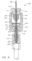
- FIG. 6 shows a further embodiment of the present invention.
- Connecting union 600 comprises an end cap 410f, a union body 420, a stopper 630, and a floating screw 440.
- a ferrule 650 is crimped onto a tubing 490 to be connected to an endfitting 470 of a column 480.
- Ferrule 650 should be able to be fixed at a predetermined position of tubing 490.
- ferrule 650 is made of metal although rigid plastics also can be used.
- End cap 410f which is similar to end cap 410e of Figure 5 and can be made of metal or rigid plastic, has an external mate thread 411 and a hole 412 through its longitudinal axis.
- hole 412 is a cylindrical hole, although other shape also can be used. The internal diameter of hole 412 is bigger than the outer diameter of tubing 490 which extends through the hole 612.
- outlet unit 430 of Figure 4a is replaced with stopper 630 and the channel 441 of the floating screw 440 is sized to accommodate the passage of tubing 490.
- Stopper 630 rests on shoulder or edge 423 and contains a hole 631 to allow passage of tubing 490.
- the length of the tubing 490 from ferrule 650 should at least equal to the sum of the length of channel 441, the thickness of stopper 630, and the pilot depth, so that tubing 490 can be placed against the bottom (i.e. pilot seat 471a) of the pilot depth 471 of the endfitting 470 while floating screw 440 is screwed onto the endfitting 470 of the column 480 as previously described.
- Stopper 630 has a concentric hole 631 aligned with hole 412 for receiving tubing 490.
- Stopper 630 can be made of metal, plastics, and other suitable material.
- stopper 630 is a metal pad of disk shape.
- the outer diameter of stopper 630 is the same as or slightly larger than the internal diameter of a major cavity 421 of the union body 420, so that stopper 630 can be inserted into major cavity 421 and holds itself in position by friction force or a press fit.
- the outer diameter of stopper 630 can also be made slightly smaller than that of major cavity 421.
- Other mechanism also can be used to secure stopper 630 in position. The movement of floating screw 440 thus is confined by stopper 630 at one end of minor cavity 422.
- Body 420, stopper 630, and floating screw 440 are preferably assembled into one assembly during manufacture. Briefly, floating screw 440 is placed into minor cavity 422 of union body 420 and confined inside minor cavity 422 by pressing stopper 630 against edge 423. To assemble tubing 490 with ferrule 650 into body 420, tubing 490 is inserted into major cavity 421 of body 420, then passes through hole 631 of stopper 630, and exits through channel 441 of floating screw 440 as illustrated in Figure 6. End cap 410f is then screwed into body 420 to trap ferrule 650 in major cavity 421.
- thread 411 of end cap 410f have a length so determined that when it is threaded to its end, ferrule 650 can rotate freely inside major cavity 421, but not move axially along tube 490.
- male thread 443 of floating screw 440 is screwed onto endfitting 470 of column 480 by turning body 420.
- tubing 490 is pushed toward the endfitting 470 by body 420 because the movement of ferrule 650 in one direction along the longitudinal axis is prohibited by end cap 410f and tubing 490 is positionally fixed into ferrule 650.
Landscapes
- Chemical & Material Sciences (AREA)
- Health & Medical Sciences (AREA)
- Analytical Chemistry (AREA)
- Chemical Kinetics & Catalysis (AREA)
- General Physics & Mathematics (AREA)
- Life Sciences & Earth Sciences (AREA)
- Biochemistry (AREA)
- General Health & Medical Sciences (AREA)
- Physics & Mathematics (AREA)
- Immunology (AREA)
- Pathology (AREA)
- Clinical Laboratory Science (AREA)
- Treatment Of Liquids With Adsorbents In General (AREA)
- Pens And Brushes (AREA)
- Mechanical Pencils And Projecting And Retracting Systems Therefor, And Multi-System Writing Instruments (AREA)
- Sampling And Sample Adjustment (AREA)
Claims (32)
- Raccord utilisé pour le raccordement d'une entrée de fluide (490) à une colonne de chromatographie (480) possédant un raccord d'extrémité (470) contenant une profondeur de guidage (471) ayant une assise de guidage (471a) en communication de fluide avec la colonne, le raccord ayant un boítier (420) avec une cavité se prolongeant à travers le boítier, caractérisé par :des moyens (423, 432, 630, 650) coopérant avec une tige tubulaire (433) servant à restreindre le mouvement de la tige tubulaire relativement au boítier (420) dans au moins une direction le long de l'axe longitudinal de la tige tubulaire ;un moyen (440) mobile relativement au boítier (420), et pouvant se déplacer et tourner le long et autour de l'axe longitudinal de la tige (433) servant à raccorder une extrémité distale (433a) de la tige tubulaire au raccord d'extrémité (470) et servant à placer l'extrémité distale de la tige tubulaire en communication fluidique hermétique avec la colonne (480) ; etun moyen (424) dans le boítier (420) coopérant avec le moyen mobile (440) afin de provoquer une rotation du moyen mobile (440) avec le boítier autour de l'axe longitudinal de la tige tubulaire (433), la rotation du boítier (420) provoquant le mouvement du moyen mobile (440) le long de l'axe longitudinal de la tige (433).
- Raccord selon la revendication 1, dans lequel une extrémité proximale (432, 630) de la tige tubulaire (433) est en communication de fluide avec l'entrée de fluide (490), et dans lequel le mouvement de la tige tubulaire relativement au boítier (420) en direction de l'extrémité proximale (432) de la tige tubulaire le long de l'axe longitudinal de la tige tubulaire est restreint (410a-f).
- Raccord selon l'une des revendications 1 à 2, dans lequel le boítier (420) comprend en outre des moyens (410a-f, 450a) servant à contenir une cartouche (450, 454) dans le boítier et à placer la cartouche en communication de fluide avec l'extrémité proximale (432) de la tige tubulaire (433) et avec l'entrée de fluide (490).
- Raccord selon l'une des revendications 1 à 3, dans lequel le mouvement de la tige tubulaire (433) relativement au boítier (420) est restreint dans les deux directions le long de l'axe longitudinal de la tige (433).
- Raccord selon l'une des revendications 1 à 4, dans lequel la cavité a une première portion (421) à l'entrée, une portion intermédiaire (422) et une portion distale (424) située en direction de la colonne (480), et dans lequel le moyen (440) mobile relativement au boítier (420) et à l'axe longitudinal de la tige tubulaire (433) servant à raccorder l'extrémité distale (433a) de la tige tubulaire (433) au raccord d'extrémité (470), comprend une vis flottante (440) avec un trou (441) à travers une longueur de la vis flottante à travers lequel la tige tubulaire (433) passe, et dans lequel la tige est adaptée pour être insérée de manière mobile dans le trou (441) de telle sorte que l'extrémité distale (433a) de la tige forme une connexion de fluide avec l'assise de guidage (471a) dans le raccord d'extrémité (470) ; et
dans lequel le moyen (424) dans le boítier (420) coopérant avec le moyen mobile (440) provoquant la rotation du moyen mobile (440) avec le boítier autour de l'axe longitudinal de la tige (433) comprend la vis flottante adaptée pour s'engager avec la portion distale de la cavité (424) de telle sorte que la vis flottante est mobile relativement au boítier (420) le long de l'axe longitudinal du boítier (420), mais avec un mouvement rotatif de la vis flottante (440) autour de l'axe longitudinal dudit boítier (420) qui est confiné par la portion distale (424) de la cavité dans le boítier. - Raccord selon l'une des revendications 1 à 5, dans lequel le moyen servant à la restriction du mouvement de la tige comprend un embout (410) s'engageant dans le boítier (420) pour limiter le mouvement de la tige (433) relativement au boítier le long de l'axe longitudinal.
- Raccord selon l'une des revendications 1 à 5 dans lequel une cartouche (450) est placée de manière amovible dans la cavité (421) dans le boítier (420), avec un embout (410) s'engageant dans le boítier et pressant la cartouche (450) vers la tige (432) pour former un passage de fluide à travers la cartouche (450) vers la tige tubulaire (432).
- Raccord selon la revendication 7 dans lequel un tampon de plastique (416) est placé entre la cartouche (450) et l'embout (410) et forme une partie du passage de fluide, dans lequel le matériau exposé audit passage de fluide est un matériau non métallique.
- Raccord selon l'une des revendications 7 et 8, dans lequel la cartouche (450) possède une première face tournée vers l'embout (410) et une seconde face tournée vers la tige (432) et la seconde face est soit d'une couleur différente, soit d'une forme différente de celle de la première face.
- Raccord selon l'une des revendications 6 à 9, dans lequel l'embout (410) a une cavité (413) servant à recevoir la cartouche (450) et une première face de la cartouche est de forme s'appariant à celle de la cavité (413) dans la cartouche (450).
- Raccord selon l'une des revendications 6 à 10, dans lequel la cavité (421) dans le boítier (420) est de forme cylindrique et au moins une partie de cette cavité (421) est filetée pour recevoir l'embout (410), et dans lequel la portion intermédiaire de la cavité (422) dans le boítier prend la forme d'une cavité cylindrique (422) de plus petit diamètre ayant un premier rebord annulaire (423), et dans lequel la tige (433) a une tête (432) à une extrémité proximale qui est adaptée pour s'engager dans le rebord (423), la tête ayant la forme d'un disque de diamètre plus grand que celui du rebord (423) afin d'empêcher le passage de la tête (432) plus loin que le rebord (423) le long de l'axe longitudinal de la tige.
- Raccord selon l'une des revendications 5 à 11, dans lequel une extrémité distale de la cavité (424) forme un canal hexagonal, et dans lequel une partie d'une vis flottante (440) se prolongeant à travers le canal hexagonal est également de forme hexagonale appariée mais légèrement plus petite.
- Raccord selon l'une des revendications 5 à 12, dans lequel la vis flottante (440) possède un rebord (445) situé dans la cavité (422) dans le boítier (420) lorsqu'il est utilisé et a une surface de section transversale plus grande que la cavité (424) dans le boítier (420) que la vis flottante traverse pour empêcher la vis flottante de se déloger de la cavité (424) dans le boítier.
- Raccord selon l'une des revendications 6 à 13, dans lequel l'embout (410) a une cavité (413, 413c) configurée pour recevoir une cartouche (450, 454) et pour placer l'entrée de fluide (490) en communication de fluide hermétique avec la cartouche (450,454).
- Raccord selon l'une des revendications 6 à 10, dans lequel la tige (433) a une extrémité proximale ayant un épaulement effilé (430a) dans lequel s'engage hermétiquement un logement de ferrule (451) associé à la cartouche (450a).
- Raccord selon l'une des revendications 1 et 2, dans lequel le moyen de restriction du mouvement de la tige comprend un embout (410) adapté pour s'engager dans le boítier (420) pour restreindre le mouvement de la tige tubulaire (433) le long de l'axe longitudinal, l'embout ayant un tube d'entrée (490) inséré à travers l'embout, avec une ferrule de positionnement (650) sertie sur le tube d'entrée s'engageant avec ledit embout, et dans lequel le tube d'entrée forme la tige tubulaire.
- Méthode de raccordement d'une entrée de fluide (490) à une colonne de chromatographie (480) ayant un raccord d'extrémité (470), le raccordement ayant un boítier (420) avec une cavité profilée se prolongeant à travers le boítier , caractérisée par les étapes consistant à :placer l'entrée de fluide (490) en communication de fluide hermétique avec la cavité profilée (421, 422, 424) se prolongeant à travers le boítier (420) ;engager une tige tubulaire (433) dans le boítier (420) pour restreindre le mouvement de la tige tubulaire relativement au boítier (420) dans au moins une direction le long de l'axe longitudinal de la tige tubulaire et pour placer la cavité profilée en communication de fluide avec une extrémité proximale (432) de la tige située dans la cavité profilée (421, 422, 424) ;prolonger la tige tubulaire (433) afin qu'elle se prolonge à travers un connecteur coaxial (440) ;contraindre le connecteur (440) à tourner avec le boítier (420) de telle sorte que la rotation du boítier provoque le mouvement du connecteur le long de l'axe longitudinal de la tige ; et, par une telle rotationfaire se déplacer le connecteur (440) relativement au boítier (420) et relativement à l'axe longitudinal de la tige (433) pour raccorder une extrémité distale (433a) de la tige tubulaire au raccord d'extrémité (470) et placer l'extrémité distale de la tige tubulaire en communication de fluide hermétique avec la colonne (480).
- Méthode selon la revendication 17, dans laquelle l'étape de placement de l'entrée de fluide (490) en communication de fluide hermétique avec la cavité profilée (421, 422, 424) comprend l'étape de vissage d'un embout (410) ayant un dispositif d'ajustage femelle (411), un logement de ferrule (415) et la profondeur de guidage (414), avec le boítier (420) afin de disposer hermétiquement une extrémité du tube d'entrée (490) contre la profondeur de guidage (414).
- Méthode selon l'une des revendications 17 et 18, comprenant l'étape supplémentaire de placement d'une cartouche (450, 454) dans le boítier et de placement de la cartouche en communication de fluide avec l'extrémité proximale (432) de la tige tubulaire (433) et avec l'entrée de fluide (490).
- Méthode selon l'une des revendications 17 et 18, dans laquelle la cartouche (450) possède une première face tournée vers l'embout (410) et une seconde face tournée vers la tige (432) et comprenant l'étape supplémentaire de formation de la seconde face avec soit une couleur différente, soit une forme différente de celle de la première face.
- Méthode selon l'une des revendications 17 à 20, comprenant l'étape supplémentaire de contrainte du mouvement de la tige tubulaire (433) relativement au boítier (420) dans les deux directions le long de l'axe longitudinal de la tige (433).
- Méthode selon l'une des revendications 17 à 21, dans laquelle la tige tubulaire (433) comprend une portion distale de l'entrée de fluide (490), et l'étape de restriction du mouvement de la tige tubulaire relativement au boítier (420) comprend l'étape de placement d'un tampon butoir (630) ayant un trou (631) pour recevoir le tube d'entrée (490) à l'intérieur de la cavité (421) et restreindre le mouvement du tampon butoir dans au moins une direction le long de l'axe longitudinal.
- Méthode selon l'une des revendications 17 à 22, dans laquelle le connecteur comprend une vis flottante (440) avec un trou (431) à travers une longueur de la vis flottante à travers lequel la tige se prolonge, et la tige est adaptée pour pouvoir être insérée de manière mobile à travers la vis de telle sorte que la vis peut tourner autour de l'axe longitudinal et se déplacer de long de l'axe longitudinal lorsque le raccordement hermétique avec l'embout (470) se forme.
- Méthode selon l'une des revendications 17 à 23, comprenant l'étape supplémentaire de formation de l'extrémité distale de la cavité (424) afin qu'elle ait un canal hexagonal, et de formation d'une partie du connecteur (440) ou de la vis flottante (440) se prolongeant à travers le canal hexagonal afin qu'elle ait également une forme hexagonale appariée, mais légèrement plus petite.
- Méthode selon l'une des revendications 17 à 23, comprenant l'étape supplémentaire de formation du connecteur (440) ou de la vis flottante (440) afin qu'ils aient un rebord (445) situé dans la cavité (422) dans le boítier (420), et de formation de ce rebord, afin qu'il soit plus grand que la cavité (424) dans le boítier (420) à travers laquelle la vis flottante ou le connecteur s'étend afin d'empêcher le connecteur ou la vis flottante de se déloger de la cavité (424) dans le boítier.
- Méthode de formation d'une connexion de fluide avec la colonne de chromatographie (480) ayant un raccord d'extrémité (470) contenant une profondeur de guidage (471) avec une assise de guidage (471a) en communication de fluide avec la colonne (480), caractérisée par les étapes consistant à :engager une cavité (421) dans le boítier (420) avec une tige tubulaire (433), la tige (433) ayant un axe longitudinal se prolongeant à travers une extrémité distale (433a) et une extrémité proximale (432) de la tige ;restreindre le mouvement de la tige (433) relativement au boítier (420) le long de l'axe longitudinal de la tige (433) dans au moins une direction ;placer l'extrémité distale (433a) de la tige (433) contre l'assise de guidage (471a) de la profondeur de guidage (471) ;déplacer un connecteur (440) le long de l'axe longitudinal pour raccorder l'extrémité distale (433a) de la tige (433) au raccord d'extrémité (470) tout en contraignant le connecteur (440) à tourner avec le boítier (420) de telle sorte que la rotation du boítier provoque le mouvement du connecteur le long de l'axe longitudinal, etplacer hermétiquement l'extrémité distale (433a) de la tige (433) en communication de fluide avec l'assise de guidage (471a) de la profondeur de guidage (471).
- Méthode selon la revendication 26, dans laquelle l'étape de restriction du mouvement de la tige (433) le long de l'axe longitudinal comprend l'étape de restriction du mouvement dans la direction de l'extrémité proximale (432) de la tige (433).
- Méthode selon l'une des revendications 26 et 27, comprenant l'étape de placement de l'extrémité proximale (432) de la tige (433) en communication de fluide avec une entrée de fluide (490).
- Méthode selon l'une des revendications 26 à 28, comprenant l'étape de placement d'une cartouche (450) dans la cavité (421) entre l'entrée de fluide (490) et l'extrémité proximale (432) de la tige (433), et en communication de fluide avec l'entrée de fluide et l'extrémité proximale (432) de la tige (433).
- Méthode selon la revendication 29, dans laquelle l'étape de placement de l'entrée de fluide (490) en communication de fluide hermétique avec la cavité (421) comprend l'étape de vissage d'un embout (410) ayant un dispositif d'ajustage femelle (411), un logement de ferrule (415) et une profondeur de guidage (414), avec le boítier (420) afin de disposer hermétiquement une extrémité du tube d'entrée (490) contre la profondeur de guidage (414).
- Connecteur pour une colonne de chromatographie (480) ayant un raccord d'extrémité (470) contenant une profondeur de guidage (471) avec une assise de guidage (471a) en communication de fluide avec la colonne (480), comprenant :des moyens (410, 460) dans le boítier (420) servant à former une connexion de fluide hermétique avec l'entrée de fluide (490) ;une tige tubulaire (433) ayant une extrémité proximale dans le boítier et adaptée de façon à être placée en communication de fluide avec l'entrée (490) lors de l'utilisation, la tige ayant un axe longitudinal se prolongeant depuis cette extrémité proximale à travers une extrémité distale (433a) de la tige ;des moyens (410, 423, 432, 630, 650) servant à restreindre le mouvement de la tige (433) relativement au boítier (420) le long de l'axe longitudinal de la tige (433) ;un moyen (440), pouvant se déplacer et tourner le long et autour de la tige tubulaire (433) et placé coaxialement avec celle-ci, servant à placer l'extrémité distale en communication de fluide hermétique avec la colonne (480) lors de l'utilisation, le boítier (420) ayant un moyen (424) contraignant le moyen mobile (440) à tourner avec le boítier (420) afin de se déplacer le long de l'axe longitudinal de la tige (433), la tige (433) se prolongeant au-delà du moyen mobile (440) pour former une connexion fluidique avec l'entrée (490).
- Connecteur selon la revendication 31, comprenant en outre une cartouche (450) dans la cavité (421) dans le boítier entre l'entrée de fluide (490) et une extrémité proximale (432) da la tige (433), et en communication de fluide avec l'entrée de fluide et l'extrémité proximale (432) de la tige (433).
Applications Claiming Priority (3)
| Application Number | Priority Date | Filing Date | Title |
|---|---|---|---|
| US2799996P | 1996-10-08 | 1996-10-08 | |
| US27999P | 1996-10-08 | ||
| PCT/US1997/017803 WO1998015824A1 (fr) | 1996-10-08 | 1997-10-03 | Porte-cartouche a raccord auto-ajustable, se vissant directement |
Publications (2)
| Publication Number | Publication Date |
|---|---|
| EP0931258A1 EP0931258A1 (fr) | 1999-07-28 |
| EP0931258B1 true EP0931258B1 (fr) | 2002-09-11 |
Family
ID=21841003
Family Applications (1)
| Application Number | Title | Priority Date | Filing Date |
|---|---|---|---|
| EP97909939A Expired - Lifetime EP0931258B1 (fr) | 1996-10-08 | 1997-10-03 | Porte-cartouche a raccord auto-ajustable, se vissant directement |
Country Status (7)
| Country | Link |
|---|---|
| US (1) | US6162362A (fr) |
| EP (1) | EP0931258B1 (fr) |
| AT (1) | ATE224055T1 (fr) |
| AU (1) | AU4743397A (fr) |
| CA (1) | CA2265822C (fr) |
| DE (1) | DE69715437T2 (fr) |
| WO (1) | WO1998015824A1 (fr) |
Families Citing this family (34)
| Publication number | Priority date | Publication date | Assignee | Title |
|---|---|---|---|---|
| US20010049517A1 (en) | 1997-03-06 | 2001-12-06 | Gholam-Reza Zadno-Azizi | Method for containing and removing occlusions in the carotid arteries |
| US6436284B1 (en) * | 1997-11-12 | 2002-08-20 | Biotage, Inc. | Chromatography apparatus |
| US20030217973A1 (en) * | 1998-08-20 | 2003-11-27 | Horsman Jeffrey A. | Method for introducing a sample into a chromatography column |
| US6783673B2 (en) | 2002-08-23 | 2004-08-31 | Biotage, Inc. | Composite chromatography column |
| DE10393207B4 (de) * | 2002-09-10 | 2022-04-07 | Waters Technologies Corp. (N.D.Ges.D. Staates Delaware) | Chromatographiesäule, Verfahren zu deren Herstellung sowie Verfahren zum Durchführen einer chromatographischen Trennung |
| AU2003270418A1 (en) * | 2002-09-12 | 2004-04-30 | Waters Investments Limited | Capillary interconnection fitting and method of holding capillary tubing |
| US6832787B1 (en) * | 2003-01-24 | 2004-12-21 | Sandia National Laboratories | Edge compression manifold apparatus |
| JP4791352B2 (ja) * | 2003-02-07 | 2011-10-12 | ウオーターズ・テクノロジーズ・コーポレイシヨン | クロマトグラフィーナノカラム用ポリマー固体支持体 |
| US20060219636A1 (en) * | 2003-02-10 | 2006-10-05 | Waters Investments Limited | Siloxane-immobilized particulate stationary phases for chromatographic separations and extractions |
| WO2005007264A2 (fr) * | 2003-07-14 | 2005-01-27 | Waters Investments Limited | Dispositif de separation presentant une colonne de garde integree |
| US20050011821A1 (en) * | 2003-07-17 | 2005-01-20 | Sigma-Aldrich Co. | High throughput flash purification stand and cartridge |
| US20050211617A1 (en) * | 2003-07-17 | 2005-09-29 | Sigma-Aldrich Co. | High throughput flash purification stand and cartridge |
| US20050011835A1 (en) * | 2003-07-17 | 2005-01-20 | Sigma-Aldrich Co. | High throughput flash purification stand and cartridge |
| WO2005015162A2 (fr) * | 2003-08-06 | 2005-02-17 | Waters Investment Limited | Terminal fluidique |
| US20070277596A1 (en) * | 2004-10-13 | 2007-12-06 | Centennial Technology Company | Automatic Chlorophyll Analyzer And Analytical Method |
| DE112005002839T5 (de) * | 2004-11-16 | 2007-12-20 | Waters Investments Ltd., New Castle | Vorrichtung zum Durchführen von Auftrennungen und Verfahren zum Herstellen und Verwenden derselben |
| WO2006063041A2 (fr) * | 2004-12-08 | 2006-06-15 | Chia-Hui Shieh | Colonne integree, systeme et procede associes pour la chromatographie liquide |
| US7316777B2 (en) * | 2005-01-28 | 2008-01-08 | Valco Instruments Co., Inc. | Compression fitting nut with interlocked ferrule |
| WO2006101610A2 (fr) | 2005-02-08 | 2006-09-28 | Aspire Medical, Inc. | Systeme et procede de glossoplastie percutanee |
| US8371307B2 (en) | 2005-02-08 | 2013-02-12 | Koninklijke Philips Electronics N.V. | Methods and devices for the treatment of airway obstruction, sleep apnea and snoring |
| US8096303B2 (en) | 2005-02-08 | 2012-01-17 | Koninklijke Philips Electronics N.V | Airway implants and methods and devices for insertion and retrieval |
| US20070000828A1 (en) * | 2005-07-01 | 2007-01-04 | Norman Wesley M | Fluid coupling |
| US20070084982A1 (en) * | 2005-10-17 | 2007-04-19 | Agilent Technologies, Inc. | Holding device for chromatograph columns |
| US20100012565A1 (en) * | 2006-01-31 | 2010-01-21 | Mallinckrodt Baker, Inc. | High Efficiency Chromatography Column with Re-usable End Cap |
| TW200734026A (en) * | 2006-01-31 | 2007-09-16 | Mallinckrodt Baker Inc | End-cap device for high efficiency disposable chromotography column |
| DE102009022368C5 (de) | 2009-05-22 | 2020-12-17 | Dionex Softron Gmbh | Steckereinheit und Verbindungssystem für das Verbinden von Kapillaren, insbesondere für die Hochleistungsflüssigkeitschromatographie |
| JP2015509606A (ja) * | 2012-03-05 | 2015-03-30 | ウオーターズ・テクノロジーズ・コーポレイシヨン | クロマトグラフィに使用されるチュービングにおける腐食保護 |
| DE102014100430B4 (de) | 2014-01-15 | 2015-08-06 | Dionex Softron Gmbh | Adaptergehäuse und eine das Adaptergehäuse umfassende Verbindungseinrichtung |
| CN103897980B (zh) * | 2014-02-26 | 2016-02-10 | 聂棱 | 一种用于生物分子提纯分离的移液枪头插取装置 |
| EP3163298B1 (fr) | 2015-10-30 | 2023-12-27 | Dionex Softron GmbH | Raccord de tube capillaire |
| EP3258259B1 (fr) * | 2016-06-13 | 2025-10-22 | Dionex Softron GmbH | Système de raccordement capillaire |
| US10935524B2 (en) | 2017-07-27 | 2021-03-02 | CEM Corporation, Lucidity Division | Gas chromatograph device with inductively heated column and method of use thereof |
| WO2022094016A1 (fr) * | 2020-10-28 | 2022-05-05 | Waters Technologies Corporation | Ensembles de positionnement de colonne de chromatographie |
| DE102020133422A1 (de) * | 2020-12-14 | 2022-06-15 | Agilent Technologies, Inc. - A Delaware Corporation - | Montagevorrichtung zum Montieren einer Probentrenneinrichtung |
Family Cites Families (15)
| Publication number | Priority date | Publication date | Assignee | Title |
|---|---|---|---|---|
| US4026803A (en) * | 1975-12-24 | 1977-05-31 | Waters Associates | Chromatographic column with improved end fittings |
| US4181853A (en) * | 1976-12-10 | 1980-01-01 | Varian Associates, Inc. | Liquid chromatography system with packed flow cell for improved fluorescence detection |
| US4173363A (en) * | 1978-07-03 | 1979-11-06 | Stearns Stanley D | Adaptor assembly for fittings and connective lines of differing sizes |
| US4283280A (en) * | 1978-08-24 | 1981-08-11 | Brownlee Labs, Inc. | Cartridge type separation column and holder assembly for liquid chromatographs |
| NL189505C (nl) * | 1979-01-02 | 1993-05-03 | Stanelle Karl Heinz | Silo met een op een opstaand gestel gemonteerd in dwarsdoorsnede cirkelvormig reservoir. |
| US4451363A (en) * | 1982-03-03 | 1984-05-29 | Brownlee Labs Inc. | Cartridge for liquid chromatograph |
| US4451364A (en) * | 1982-03-03 | 1984-05-29 | Brownlee Labs Inc. | High pressure seal and coupling |
| US4565632A (en) * | 1985-01-11 | 1986-01-21 | Beckman Instruments, Inc. | Chromatographic cartridge column system |
| DE3637916A1 (de) * | 1986-11-06 | 1988-05-19 | Labomatic Gmbh | Chromatographiesaeule |
| US5227059A (en) * | 1989-11-08 | 1993-07-13 | Alltech Associates, Inc. | Chromatography columns |
| US5338448A (en) * | 1992-10-16 | 1994-08-16 | Sarasep, Inc. | Method of preventing contamination of a chromatography column |
| DE4326568A1 (de) * | 1993-08-07 | 1995-02-09 | Edgar Grom | Kapillar-HPLC-Säulen-System |
| EP0713416B1 (fr) * | 1993-08-12 | 1999-03-17 | Optimize technologies, Inc. | Raccord integral et filtre |
| US5472598A (en) * | 1994-04-15 | 1995-12-05 | Upchurch Scientific, Inc. | Connection assembly for liquid chromatography columns |
| US5482628A (en) * | 1994-04-15 | 1996-01-09 | Upchurch Scientific, Inc. | Column for liquid chromatography |
-
1997
- 1997-10-03 WO PCT/US1997/017803 patent/WO1998015824A1/fr not_active Ceased
- 1997-10-03 CA CA002265822A patent/CA2265822C/fr not_active Expired - Fee Related
- 1997-10-03 US US08/943,851 patent/US6162362A/en not_active Expired - Lifetime
- 1997-10-03 AU AU47433/97A patent/AU4743397A/en not_active Abandoned
- 1997-10-03 DE DE69715437T patent/DE69715437T2/de not_active Expired - Fee Related
- 1997-10-03 AT AT97909939T patent/ATE224055T1/de not_active IP Right Cessation
- 1997-10-03 EP EP97909939A patent/EP0931258B1/fr not_active Expired - Lifetime
Also Published As
| Publication number | Publication date |
|---|---|
| CA2265822C (fr) | 2005-11-29 |
| ATE224055T1 (de) | 2002-09-15 |
| CA2265822A1 (fr) | 1998-04-16 |
| EP0931258A1 (fr) | 1999-07-28 |
| AU4743397A (en) | 1998-05-05 |
| US6162362A (en) | 2000-12-19 |
| DE69715437D1 (de) | 2002-10-17 |
| WO1998015824A1 (fr) | 1998-04-16 |
| DE69715437T2 (de) | 2003-10-23 |
Similar Documents
| Publication | Publication Date | Title |
|---|---|---|
| EP0931258B1 (fr) | Porte-cartouche a raccord auto-ajustable, se vissant directement | |
| EP0713416B1 (fr) | Raccord integral et filtre | |
| US5730943A (en) | Integral fitting and filter of an analytical chemical instrument | |
| US9945501B2 (en) | Plug unit and connection system for connecting capillary tubes | |
| US6494500B1 (en) | Universal high pressure liquid connector | |
| US5227059A (en) | Chromatography columns | |
| US6095572A (en) | Quarter turn quick connect fitting | |
| US10816115B2 (en) | Capillary connection system | |
| EP2870469B1 (fr) | Joint de virole monopièce à partie conique contre-dépouillée | |
| US20080309076A1 (en) | Device and Method for a Fluid-Tight Connection | |
| EP2701821A1 (fr) | Ensembles de raccords | |
| US12411114B2 (en) | Chromatography column adaptor and use for fluidic connections | |
| GB2601251A (en) | Low dead-volume connector for fluid chromatography | |
| US20120119491A1 (en) | Hollow Fiber Connection | |
| US20060213824A1 (en) | Column fitting device and method | |
| JP2025099344A (ja) | クロマトグラフ用チューブ |
Legal Events
| Date | Code | Title | Description |
|---|---|---|---|
| PUAI | Public reference made under article 153(3) epc to a published international application that has entered the european phase |
Free format text: ORIGINAL CODE: 0009012 |
|
| 17P | Request for examination filed |
Effective date: 19990305 |
|
| AK | Designated contracting states |
Kind code of ref document: A1 Designated state(s): AT BE CH DE DK ES FI FR GB GR IE IT LI LU MC NL PT SE |
|
| 17Q | First examination report despatched |
Effective date: 20010510 |
|
| GRAG | Despatch of communication of intention to grant |
Free format text: ORIGINAL CODE: EPIDOS AGRA |
|
| GRAG | Despatch of communication of intention to grant |
Free format text: ORIGINAL CODE: EPIDOS AGRA |
|
| GRAH | Despatch of communication of intention to grant a patent |
Free format text: ORIGINAL CODE: EPIDOS IGRA |
|
| GRAH | Despatch of communication of intention to grant a patent |
Free format text: ORIGINAL CODE: EPIDOS IGRA |
|
| GRAA | (expected) grant |
Free format text: ORIGINAL CODE: 0009210 |
|
| AK | Designated contracting states |
Kind code of ref document: B1 Designated state(s): AT BE CH DE DK ES FI FR GB GR IE IT LI LU MC NL PT SE |
|
| PG25 | Lapsed in a contracting state [announced via postgrant information from national office to epo] |
Ref country code: NL Free format text: LAPSE BECAUSE OF FAILURE TO SUBMIT A TRANSLATION OF THE DESCRIPTION OR TO PAY THE FEE WITHIN THE PRESCRIBED TIME-LIMIT Effective date: 20020911 Ref country code: LI Free format text: LAPSE BECAUSE OF FAILURE TO SUBMIT A TRANSLATION OF THE DESCRIPTION OR TO PAY THE FEE WITHIN THE PRESCRIBED TIME-LIMIT Effective date: 20020911 Ref country code: IT Free format text: LAPSE BECAUSE OF FAILURE TO SUBMIT A TRANSLATION OF THE DESCRIPTION OR TO PAY THE FEE WITHIN THE PRESCRIBED TIME-LIMIT;WARNING: LAPSES OF ITALIAN PATENTS WITH EFFECTIVE DATE BEFORE 2007 MAY HAVE OCCURRED AT ANY TIME BEFORE 2007. THE CORRECT EFFECTIVE DATE MAY BE DIFFERENT FROM THE ONE RECORDED. Effective date: 20020911 Ref country code: GR Free format text: LAPSE BECAUSE OF FAILURE TO SUBMIT A TRANSLATION OF THE DESCRIPTION OR TO PAY THE FEE WITHIN THE PRESCRIBED TIME-LIMIT Effective date: 20020911 Ref country code: FI Free format text: LAPSE BECAUSE OF FAILURE TO SUBMIT A TRANSLATION OF THE DESCRIPTION OR TO PAY THE FEE WITHIN THE PRESCRIBED TIME-LIMIT Effective date: 20020911 Ref country code: CH Free format text: LAPSE BECAUSE OF FAILURE TO SUBMIT A TRANSLATION OF THE DESCRIPTION OR TO PAY THE FEE WITHIN THE PRESCRIBED TIME-LIMIT Effective date: 20020911 Ref country code: BE Free format text: LAPSE BECAUSE OF FAILURE TO SUBMIT A TRANSLATION OF THE DESCRIPTION OR TO PAY THE FEE WITHIN THE PRESCRIBED TIME-LIMIT Effective date: 20020911 Ref country code: AT Free format text: LAPSE BECAUSE OF FAILURE TO SUBMIT A TRANSLATION OF THE DESCRIPTION OR TO PAY THE FEE WITHIN THE PRESCRIBED TIME-LIMIT Effective date: 20020911 |
|
| REF | Corresponds to: |
Ref document number: 224055 Country of ref document: AT Date of ref document: 20020915 Kind code of ref document: T |
|
| REG | Reference to a national code |
Ref country code: GB Ref legal event code: FG4D |
|
| REG | Reference to a national code |
Ref country code: CH Ref legal event code: EP |
|
| PG25 | Lapsed in a contracting state [announced via postgrant information from national office to epo] |
Ref country code: LU Free format text: LAPSE BECAUSE OF NON-PAYMENT OF DUE FEES Effective date: 20021003 |
|
| REG | Reference to a national code |
Ref country code: IE Ref legal event code: FG4D |
|
| REF | Corresponds to: |
Ref document number: 69715437 Country of ref document: DE Date of ref document: 20021017 |
|
| ET | Fr: translation filed | ||
| PG25 | Lapsed in a contracting state [announced via postgrant information from national office to epo] |
Ref country code: SE Free format text: LAPSE BECAUSE OF FAILURE TO SUBMIT A TRANSLATION OF THE DESCRIPTION OR TO PAY THE FEE WITHIN THE PRESCRIBED TIME-LIMIT Effective date: 20021211 Ref country code: DK Free format text: LAPSE BECAUSE OF FAILURE TO SUBMIT A TRANSLATION OF THE DESCRIPTION OR TO PAY THE FEE WITHIN THE PRESCRIBED TIME-LIMIT Effective date: 20021211 |
|
| PG25 | Lapsed in a contracting state [announced via postgrant information from national office to epo] |
Ref country code: PT Free format text: LAPSE BECAUSE OF FAILURE TO SUBMIT A TRANSLATION OF THE DESCRIPTION OR TO PAY THE FEE WITHIN THE PRESCRIBED TIME-LIMIT Effective date: 20021217 |
|
| NLV1 | Nl: lapsed or annulled due to failure to fulfill the requirements of art. 29p and 29m of the patents act | ||
| REG | Reference to a national code |
Ref country code: CH Ref legal event code: PL |
|
| PG25 | Lapsed in a contracting state [announced via postgrant information from national office to epo] |
Ref country code: ES Free format text: LAPSE BECAUSE OF FAILURE TO SUBMIT A TRANSLATION OF THE DESCRIPTION OR TO PAY THE FEE WITHIN THE PRESCRIBED TIME-LIMIT Effective date: 20030328 |
|
| PLBE | No opposition filed within time limit |
Free format text: ORIGINAL CODE: 0009261 |
|
| STAA | Information on the status of an ep patent application or granted ep patent |
Free format text: STATUS: NO OPPOSITION FILED WITHIN TIME LIMIT |
|
| 26N | No opposition filed |
Effective date: 20030612 |
|
| PGFP | Annual fee paid to national office [announced via postgrant information from national office to epo] |
Ref country code: MC Payment date: 20081022 Year of fee payment: 12 Ref country code: IE Payment date: 20081028 Year of fee payment: 12 Ref country code: DE Payment date: 20081028 Year of fee payment: 12 |
|
| PGFP | Annual fee paid to national office [announced via postgrant information from national office to epo] |
Ref country code: FR Payment date: 20081021 Year of fee payment: 12 |
|
| PGFP | Annual fee paid to national office [announced via postgrant information from national office to epo] |
Ref country code: GB Payment date: 20081024 Year of fee payment: 12 |
|
| PG25 | Lapsed in a contracting state [announced via postgrant information from national office to epo] |
Ref country code: MC Free format text: LAPSE BECAUSE OF NON-PAYMENT OF DUE FEES Effective date: 20091031 |
|
| REG | Reference to a national code |
Ref country code: IE Ref legal event code: MM4A |
|
| REG | Reference to a national code |
Ref country code: FR Ref legal event code: ST Effective date: 20100630 |
|
| PG25 | Lapsed in a contracting state [announced via postgrant information from national office to epo] |
Ref country code: FR Free format text: LAPSE BECAUSE OF NON-PAYMENT OF DUE FEES Effective date: 20091102 Ref country code: DE Free format text: LAPSE BECAUSE OF NON-PAYMENT OF DUE FEES Effective date: 20100501 |
|
| PG25 | Lapsed in a contracting state [announced via postgrant information from national office to epo] |
Ref country code: IE Free format text: LAPSE BECAUSE OF NON-PAYMENT OF DUE FEES Effective date: 20091005 |
|
| PG25 | Lapsed in a contracting state [announced via postgrant information from national office to epo] |
Ref country code: GB Free format text: LAPSE BECAUSE OF NON-PAYMENT OF DUE FEES Effective date: 20091003 |