EP0930960B1 - System, appliance and cartridge for personal body care - Google Patents
System, appliance and cartridge for personal body care Download PDFInfo
- Publication number
- EP0930960B1 EP0930960B1 EP98910931A EP98910931A EP0930960B1 EP 0930960 B1 EP0930960 B1 EP 0930960B1 EP 98910931 A EP98910931 A EP 98910931A EP 98910931 A EP98910931 A EP 98910931A EP 0930960 B1 EP0930960 B1 EP 0930960B1
- Authority
- EP
- European Patent Office
- Prior art keywords
- cartridge
- appliance
- key
- blocking device
- auxiliary fluid
- Prior art date
- Legal status (The legal status is an assumption and is not a legal conclusion. Google has not performed a legal analysis and makes no representation as to the accuracy of the status listed.)
- Expired - Lifetime
Links
Images


Classifications
-
- B—PERFORMING OPERATIONS; TRANSPORTING
- B26—HAND CUTTING TOOLS; CUTTING; SEVERING
- B26B—HAND-HELD CUTTING TOOLS NOT OTHERWISE PROVIDED FOR
- B26B19/00—Clippers or shavers operating with a plurality of cutting edges, e.g. hair clippers, dry shavers
- B26B19/38—Details of, or accessories for, hair clippers, or dry shavers, e.g. housings, casings, grips, guards
- B26B19/3873—Electric features; Charging; Computing devices
- B26B19/388—Sensors; Control
-
- B—PERFORMING OPERATIONS; TRANSPORTING
- B26—HAND CUTTING TOOLS; CUTTING; SEVERING
- B26B—HAND-HELD CUTTING TOOLS NOT OTHERWISE PROVIDED FOR
- B26B19/00—Clippers or shavers operating with a plurality of cutting edges, e.g. hair clippers, dry shavers
- B26B19/38—Details of, or accessories for, hair clippers, or dry shavers, e.g. housings, casings, grips, guards
- B26B19/3806—Accessories
- B26B19/382—Built-in accessories
-
- B—PERFORMING OPERATIONS; TRANSPORTING
- B26—HAND CUTTING TOOLS; CUTTING; SEVERING
- B26B—HAND-HELD CUTTING TOOLS NOT OTHERWISE PROVIDED FOR
- B26B19/00—Clippers or shavers operating with a plurality of cutting edges, e.g. hair clippers, dry shavers
- B26B19/38—Details of, or accessories for, hair clippers, or dry shavers, e.g. housings, casings, grips, guards
- B26B19/3886—Actuating members, e.g. switches or control knobs
-
- B—PERFORMING OPERATIONS; TRANSPORTING
- B26—HAND CUTTING TOOLS; CUTTING; SEVERING
- B26B—HAND-HELD CUTTING TOOLS NOT OTHERWISE PROVIDED FOR
- B26B19/00—Clippers or shavers operating with a plurality of cutting edges, e.g. hair clippers, dry shavers
- B26B19/38—Details of, or accessories for, hair clippers, or dry shavers, e.g. housings, casings, grips, guards
- B26B19/40—Lubricating
Definitions
- the invention relates to an appliance for body care, comprising
- the invention also relates to a cartridge comprising
- the invention also relates to a system suitable for personal body care, comprising a cartridge having a space for storing an auxiliary fluid, and an appliance.
- Such a system such an appliance and such a cartridge are known from US-A-5,402,697.
- the known system comprises an electric shaver and a cartridge filled with a depilatory substance.
- the shaver has a shaving head, a drive unit and a chamber for mounting the cartridge. Viewed from the shaving head the chamber is located adjacent the drive unit and, at the shaver side remote from the shaving head, it has a cover to enable the cartridge to be placed into the chamber. At the shaving head side the chamber communicates with a passage which terminates in the outer surface of the shaving head.
- the cartridge has an actuating button to apply the depilatory substance.
- the cover has an opening through which a user has access to the button in the closed position of the cover once the cartridge has been placed into the shaver.
- a drawback of the known system is that the shaver can be used in conjunction with a cartridge containing a fluid which has not been tested in combination with the shaver.
- the appliance in accordance with the invention includes a blocking device adapted to block at least one function of the appliance, and the blocking device is adapted to unblock said function when a cartridge having a key is coupled to the appliance.
- the cartridge in accordance with the invention has a key for unblocking a function of the appliance when the cartridge is coupled to the appliance.
- the system in accordance with the invention comprises a cartridge having a space for storing an auxiliary fluid and an appliance according to claim 1.
- the invention is based on the recognition of the fact-that the use of an auxiliary fluid in conjunction with an appliance which performs a body-care treatment on the body of a user imposes special requirements on the auxiliary fluid. It is not sufficient that the auxiliary fluid as such is suitable for application to the body. It appears that the effect on the body can change under the influence of the treatment.
- the auxiliary fluid should be easy to remove from the appliance and the auxiliary fluid should not affect the appliance.
- the measures in accordance with the invention inhibit a function which could give an undesired result when a cartridge without the correct key is present. Protection against undesired results is achieved in that cartridges having the correct key are filled exclusively with fluids that have been tested in conjunction with the appliance.
- An embodiment of the appliance in accordance with the invention is characterized as defined in the characterizing part of Claim 2. Thus, application of an unsuitable auxiliary fluid is precluded.
- An embodiment of the appliance in accordance with the invention is characterized as defined in the characterizing part of Claim 3.
- This embodiment is particularly interesting if the treatment is possible both "dry”, i.e. without an auxiliary fluid, and "wet", i.e. with an auxiliary fluid.
- said measure precludes the application of an unfit auxiliary fluid, for example, in that the pump is blocked while allowing the appliance to be used in the "dry" mode.
- An embodiment of the appliance in accordance with the invention is characterized as defined in the characterizing part of Claim 4.
- This embodiment is particularly suitable for blocking mechanical functions such as, for example, the actuation of a valve or the drive of a pump.
- this embodiment has the advantage that it is comparatively immune to soiling. Such a soiling is for example not unlikely to be caused by the auxiliary fluid.
- this embodiment is not dependent upon an electric power source, which precludes failure of the blocking device owing to, for example, an inadequate battery voltage.
- An embodiment of the appliance in accordance with the invention is characterized as defined in the characterizing part of Claim 5. Owing to this measure it is achieved that both the size and the position of a pin-shaped projection form variables for defining different keys. As a result of this, a body care system can include cartridges with mutually different fluids and different keys. It may then be desirable to block different functions in the appliances of the system in dependence on the key.
- a key having two different variables enables new appliances and fluids to be put on the market with the possibility of allowing operation of old appliances in combination with the new fluids and blocking new appliances for the old fluids, or of blocking the old appliances for the new fluid and allowing operation of the new appliances for the old fluids.
- An embodiment of the appliance in accordance with the invention is characterized as defined in the characterizing part of Claim 6. Such a symmetry simplifies mounting of the cartridge on the appliance because the cartridge can be coupled to the appliance in two positions.
- An embodiment of the appliance in accordance with the invention is characterized as defined in the characterizing part of Claim 7.
- the key may then comprise, for example, a pattern of more reflecting and less reflecting surfaces which is read out when the cartridge is placed into the appliance. By means of this measure it is achieved that no forces occur between the cartridge and the appliance as a result of the presence of the key.
- An embodiment of the appliance in accordance with the invention is characterized as defined in the characterizing part of Claim 8.
- the key can, for example, take the form of a magnetic strip, the magnetic detector being sensitive to a magnetic pattern provided in the magnetic strip.
- the key may include an inductive element and the magnetic detector may include an antenna for the generation and detection of an alternating magnetic field.
- An embodiment of the appliance in accordance with the invention is characterized as defined in the characterizing part of Claim 9. Owing to this measure it is achieved that an electrically controlled function of the appliance can be blocked by simple means.
- the key may then comprise a pattern of electrode surfaces, connected or not connected to one another, and the electrical detector may comprise a pattern of two or more electrodes.
- the electrode surfaces may then be connected via a given electrical resistance, capacitance or inductance, or they may form a digital pattern of surfaces, electrically connected or not electrically connected to one another.
- An embodiment of the cartridge in accordance with the invention is characterized as defined in the characterizing part of Claim 11. Owing to these measures the shape of the key is non-critical, so that it can be manufactured reliably in a mass-production process.
- An embodiment of the cartridge in accordance with the invention is characterized as defined in the characterizing part of Claim 12. By means of this measure it is achieved that the number of variables for the defining the key further increases.
- An embodiment of the cartridge in accordance with the invention is characterized as defined in the characterizing part of Claim 13. As a result of this, mounting of the cartridge on the appliance is simplified because the cartridge can be coupled to the appliance in two positions.
- An embodiment of the cartridge in accordance with the invention is characterized as defined in the characterizing part of Claim 17.
- the pump can be replaced easily.
- the hygiene of the system can be improved by, for example, selling a package including five reservoirs and one pump.
- the key forms part of the pump the package as a whole can be manufactured more cheaply.
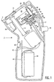
- FIG. 1 shows a first embodiment of the system in accordance with the invention.
- the system comprises an electric shaver 1 and a cartridge 2 accommodated in a chamber 12 of the shaver 1.
- the shaver 1 comprises a treatment device, in the present case a shaving head 3 having drivable cutters 31 and an electric motor 11 for driving the cutters 31 via a coupling pin 14.
- the cartridge 2 comprises a diaphragm pump 23 and a reservoir 25 having a space 21 for holding an auxiliary fluid.
- This auxiliary fluid preferably has a lubrication component for reducing the friction between the shaving head 3 and the skin of a user and is preferably a shaving lotion.
- the cartridge 2 has an outlet channel 22 for applying the auxiliary fluid.
- the shaver 1 further has an interface for coupling the cartridge 2.
- the interface of the shaver 1 comprises hooks 19 which engage with hooks 24 of an interface of the cartridge 2.
- the hooks 19 and 24 have been shaped in such a manner that mounting and removal of the cartridge 2 requires some effort.
- the interface of the shaver 1 further comprises a coupling element for the passage of the auxiliary fluid, in the present case a tubular portion 33, for coupling an outlet opening 32 to the outlet channel 22.
- the shaver 1 comprises an actuator 13, which extends into the chamber 12.
- the actuator 13 is coupled to a button 15 on the outside of the shaver 1, in such a manner that the actuator 13 can be driven by moving the button 15.
- the diaphragm pump 23 supplies a small amount of the auxiliary fluid via the outlet opening 32.
- the cartridge 2 has a mechanical key 50 which cooperates with a blocking device 60, which is adapted to block the lever 17 via pins.
- the key 50 has projections for positioning the pins of the blocking device 60. The dimensions of the projections determine whether or not the pins of the blocking device 60 block the actuation of the pump 23. In the absence of the correct key the lever 17 is blocked and thus prevents the auxiliary fluid in the cartridge from being pumped to the outlet opening 32.
- the shaver 1 further has a battery 44, which can be coupled to the motor 11 via a switch 42 mounted on a printed circuit board 41.
- the switch 42 can be actuated by means of a button 43 on the outside of the shaver 1.
- no auxiliary fluid is needed for shaving and the blocking device 60 allows shaving if no cartridge is present.
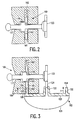
- FIG. 2 is a diagrammatic representation of a part of a second embodiment of the invention, in which an actuating function is blocked.
- a slide 117 for the actuation of a pump 123 is blocked by means of a blocking device 160.
- the blocking device 160 further comprises a blocking element 161, which is held in a blocking position by a resilient element 162. In this blocking position the actuation of the pump is blocked in that the blocking element 161 forms a stop for a projection 118 on the slide 117.
- the advantage of mechanically blocking the slide 117 is that the user feels that the pump function is blocked. Thus, it is avoided that he draws the conclusion that the cartridge is empty or that clogging has occurred.
- Figure 3 is a diagrammatic representation of a part of the second embodiment of the invention, in which the actuating function is not blocked.
- an opening 163 in the blocking element 161 is positioned in such a manner that the projection 118 is free and the pump 123 can be actuated via the slide 117.
- the blocking element 161 is moved into the non-blocking position by a key which forms part of a cartridge 102.
- the cartridge 102 holds an auxiliary fluid, which is enclosed by the flange 120 and a flexible wall 121.
- the flange 120 has a coupling element 122 for the passage of the auxiliary fluid.
- the key comprises a pin 151 whose position on the flange corresponds to that of an opening 165 of the blocking device 160 when the coupling element 122 is in line with a coupling element 124 of the pump 123.
- the key has a key surface 153 which engages against a contact surface 164 of the blocking element 161.
- the pin 151 has a such a length 1 that the blocking element 161 is held in its non-blocking position against the pressure of the resilient element 162.
- the key on the cartridge 102 comprises a second pin 152 having the same length as the pin 151.
- the second pin 152 likewise has a key surface adapted to cooperate with the contact surface 164.
- the pins 151 and 152 are disposed symmetrically with respect to the coupling element 122. Owing to this symmetry the cartridge 102 can be mounted in two different positions which are spaced 180 degrees apart.
- Figure 4 is a diagrammatic representation of a part of a third embodiment of the invention.
- the key comprises two pins 251 and 252 arranged symmetrically with respect to a coupling element 222.
- the pins 251 and 252 form parts of a flange 220 which is connected to a flexible pouch, not shown.
- the blocking device 260 comprises two blocking elements 261 and 262 held in a blocking position by two springs 263 and 264. In this blocking position the blocking elements 261 and 262 block two projections 271 and 272 which form pans of actuating slides 273 and 274, so that the functions controlled by the actuating slides 273 and 274 are blocked.
- the slides 271 and 272 may be coupled in such a manner that both slides should not be blocked to actuate a function.
- the blocking elements 271 and 272 may be coupled in such a way that the presence of one of the two pins 251 and 252 is adequate to set the blocking elements 271 and 272 to a non-blocking position.
- Figure 5 is a diagrammatic representation of a part of the third embodiment of the invention, in which the flange 220 in a first position cooperates with the blocking device 260 and said functions are not blocked. In the non-blocking positions of the blocking elements 261 and 262 the projections 271 and 272 are free, so that the actuating slides 273 and 274 can be moved in a direction perpendicular to the plane of drawing.
- Figure 6 is a diagrammatic representation of a part of the third embodiment of the invention, in which the flange 220 in a second position cooperates with the blocking device 260 and in which said functions are not blocked.
- the blocking device 260 is symmetrical and each blocking element has two non-blocking positions.
- the flange 220 can be mounted in tow different positions which are 180 degrees spaced apart, while the key is asymmetrical.
- the blocking device 260 is also unblocked by a key having two pins of a length equal to that of the pin 251 or of the pin 252.
- Figure 7 shows a part of an embodiment having an optical key and an optical detector.
- a cartridge 302 has a bar code 350 which can be read by an optical detector 361 when the cartridge is placed into a suitable chamber 312 in an appliance in accordance with the invention.
- the appliance further comprises a control unit 363 including a detection circuit.
- the control unit wholly or partly enables the drive to be applied to a motor 11 upon detection of the correct bar code.
- the motor 11 serves, for example, for driving cutters as shown in Figure 1.
- Figure 8 shows a part of an embodiment having an electrical key and an electrical detector.
- a cartridge 402 has two contact surfaces 451 and 452 interconnected via a resistor 453 having a given resistance value.
- this resistance value can be measured by means of a measurement circuit of a control unit 463 and two electrodes 461 and 462. Upon detection of given resistance values certain speeds of the motor 11 are no longer inhibited.
- FIG. 9 shows a part of an embodiment having an electromagnetic key and an electromagnetic detector.
- a cartridge 502 comprises a resonant circuit 550, which can be read out by means of an antenna 561 when the cartridge 502 is present in a suitable chamber 512 in an appliance in accordance with the invention.
- the appliance further comprises a control unit 563 having a decoder circuit which wholly or partly enables the drive to be applied to a motor 11 upon detection of the correct resonant frequency.
- Figure 10 shows a part of an embodiment having a magnetic key and a magnetic head.
- a cartridge 602 has a magnetic strip 650 which can be read out by means of a magnetic head 661 when the cartridge is placed into a suitable chamber 612 in an appliance in accordance with the invention.
- the appliance further comprises a control unit 663 having a decoder circuit which wholly or partly enables the drive to be applied to a motor 11 upon detection of the correct code on the magnetic strip.
- the blockable function can also involve a treatment of a given type or a give treatment speed.
- the auxiliary fluid may be a massaging oil, a higher massaging speed being allowed when a cartridge having the correct is present.
- the appliance can be constructed as an electric toothbrush, a depilation device or a steaming device, the auxiliary fluid being, for example, a toothpaste, a body-care cream or a menthol preparation.
Landscapes
- Life Sciences & Earth Sciences (AREA)
- Forests & Forestry (AREA)
- Engineering & Computer Science (AREA)
- Mechanical Engineering (AREA)
- Feeding And Controlling Fuel (AREA)
- Dry Shavers And Clippers (AREA)
- Telephone Function (AREA)
- Measuring Pulse, Heart Rate, Blood Pressure Or Blood Flow (AREA)
- Devices For Medical Bathing And Washing (AREA)
- Containers And Packaging Bodies Having A Special Means To Remove Contents (AREA)
Priority Applications (1)
| Application Number | Priority Date | Filing Date | Title |
|---|---|---|---|
| EP98910931A EP0930960B1 (en) | 1997-06-05 | 1998-04-09 | System, appliance and cartridge for personal body care |
Applications Claiming Priority (4)
| Application Number | Priority Date | Filing Date | Title |
|---|---|---|---|
| EP97201704 | 1997-06-05 | ||
| EP97201704 | 1997-06-05 | ||
| EP98910931A EP0930960B1 (en) | 1997-06-05 | 1998-04-09 | System, appliance and cartridge for personal body care |
| PCT/IB1998/000545 WO1998055274A1 (en) | 1997-06-05 | 1998-04-09 | System, appliance and cartridge for personal body care |
Publications (2)
| Publication Number | Publication Date |
|---|---|
| EP0930960A1 EP0930960A1 (en) | 1999-07-28 |
| EP0930960B1 true EP0930960B1 (en) | 2003-08-06 |
Family
ID=8228409
Family Applications (1)
| Application Number | Title | Priority Date | Filing Date |
|---|---|---|---|
| EP98910931A Expired - Lifetime EP0930960B1 (en) | 1997-06-05 | 1998-04-09 | System, appliance and cartridge for personal body care |
Country Status (7)
| Country | Link |
|---|---|
| US (1) | US6131288A (enExample) |
| EP (1) | EP0930960B1 (enExample) |
| JP (1) | JP4341988B2 (enExample) |
| AT (1) | ATE246576T1 (enExample) |
| DE (1) | DE69816960T2 (enExample) |
| ES (1) | ES2202822T3 (enExample) |
| WO (1) | WO1998055274A1 (enExample) |
Cited By (1)
| Publication number | Priority date | Publication date | Assignee | Title |
|---|---|---|---|---|
| DE102005063196A1 (de) * | 2005-12-30 | 2007-07-05 | Braun Gmbh | Applikationsstoffbehälter für Zahnbürsten und elektrische Zahnbürste |
Families Citing this family (41)
| Publication number | Priority date | Publication date | Assignee | Title |
|---|---|---|---|---|
| ES2232197T3 (es) * | 1998-12-29 | 2005-05-16 | Koninklijke Philips Electronics N.V. | Aparato para afeitar. |
| DE19907224C2 (de) * | 1999-02-19 | 2001-02-22 | Braun Gmbh | Flüssigkeitsbehälter |
| DE19907025A1 (de) | 1999-02-19 | 2000-08-31 | Braun Gmbh | Haarentfernungsgerät |
| US6530150B1 (en) * | 1999-05-17 | 2003-03-11 | Benjamin J. Barish | Attachments for electrical shaver and auxiliary cleaning device useful for electrical shaver |
| DE60024321T2 (de) * | 1999-12-10 | 2006-08-17 | Sensopad Ltd., Harston | Mensch/maschine-schnittstelle |
| US7086111B2 (en) | 2001-03-16 | 2006-08-08 | Braun Gmbh | Electric dental cleaning device |
| DE10159395B4 (de) | 2001-12-04 | 2010-11-11 | Braun Gmbh | Vorrichtung zur Zahnreinigung |
| PL197332B1 (pl) | 2001-03-14 | 2008-03-31 | Braun Gmbh | Sposób czyszczenia zębów za pomocą elektrycznego przyrządu do czyszczenia zębów, uchwyt elektrycznego przyrządu do czyszczenia zębów, narzędzie czyszczące i elektryczny przyrząd do czyszczenia zębów |
| WO2003068466A1 (en) * | 2002-02-13 | 2003-08-21 | Matsushita Electric Works, Ltd. | Hair removing device with a lotion applicator |
| US7438202B2 (en) * | 2002-12-03 | 2008-10-21 | Koninklijke Philips Electronics N.V. | Hair removing apparatus |
| US20040107578A1 (en) * | 2002-12-04 | 2004-06-10 | Steele James M. | Blade sharpening for electric shavers |
| CA2508268A1 (en) * | 2002-12-19 | 2004-07-08 | Koninklijke Philips Electronics N.V. | Discrete-amount fluid-dispensing system for a personal care device |
| ES2326120T3 (es) | 2003-06-30 | 2009-10-01 | Koninklijke Philips Electronics N.V. | Aparato, cartucho y sistema para el cuidado personal con fluido auxiliar. |
| US7137203B2 (en) * | 2003-12-30 | 2006-11-21 | Eveready Battery Company, Inc. | Shaving apparatus |
| DE102004015759A1 (de) * | 2004-03-31 | 2005-10-20 | Braun Gmbh | Elektrisches Haarentfernungsgerät zum partiellen oder vollständigen Entfernen von Haaren von der Haut |
| US8615886B1 (en) * | 2004-05-06 | 2013-12-31 | Winthrop D. Childers | Shaving system with energy imparting device |
| MX2007013787A (es) | 2005-05-03 | 2008-01-22 | Colgate Palmolive Co | Cepillo de dientes musical. |
| ATE439058T1 (de) | 2005-06-16 | 2009-08-15 | Koninkl Philips Electronics Nv | Kartusche für eine körperpflegeanwendung und anwendung mit derartiger kartusche |
| US7367126B2 (en) * | 2005-09-06 | 2008-05-06 | The Gillette Company | Powered wet-shaving razor |
| US7788810B2 (en) * | 2006-07-24 | 2010-09-07 | Eveready Battery Company, Inc. | Shaving system having an umbilical |
| US20090263176A1 (en) * | 2008-04-21 | 2009-10-22 | Mileti Robert J | Replaceable Cartridge Dispenser Assembly |
| CN102014696B (zh) | 2008-05-07 | 2014-06-25 | 高露洁-棕榄公司 | 交互式牙刷和可移除式音频输出模块 |
| EP2236054A1 (en) * | 2009-04-04 | 2010-10-06 | Braun GmbH | Body grooming device |
| CN102452091B (zh) | 2010-10-28 | 2015-08-12 | 吉列公司 | 用于毛发移除装置的具有导流板的施用装置 |
| CN102452085B (zh) | 2010-10-28 | 2016-01-27 | 吉列公司 | 用于分配液体的毛发移除装置的泵 |
| CN102452095B (zh) | 2010-10-28 | 2014-10-29 | 吉列公司 | 用于分配液体的毛发移除装置的施用装置 |
| CN102452096A (zh) | 2010-10-28 | 2012-05-16 | 吉列公司 | 用于分配液体的毛发移除装置的柄部 |
| CN102452094A (zh) | 2010-10-28 | 2012-05-16 | 吉列公司 | 分配液体的毛发移除套件 |
| CN102452092B (zh) | 2010-10-28 | 2015-04-01 | 吉列公司 | 分配液体的毛发移除装置 |
| CN102452088B (zh) | 2010-10-28 | 2015-07-01 | 吉列公司 | 具有刀片架保持覆盖件的毛发移除装置 |
| US8808060B2 (en) | 2011-04-12 | 2014-08-19 | Clipp-Aid Llc | Systems and methods for sharpening cutting blades |
| US20130020351A1 (en) * | 2011-07-21 | 2013-01-24 | Gojo Industries, Inc. | Dispenser with optical keying system |
| CA2841901A1 (en) | 2011-07-25 | 2013-01-31 | Braun Gmbh | Linear electro-polymer motors and devices having the same |
| ES2534822T3 (es) | 2011-07-25 | 2015-04-29 | Braun Gmbh | Dispositivo de higiene bucodental |
| PL2550937T3 (pl) | 2011-07-25 | 2014-07-31 | Braun Gmbh | Magnetyczne połączenie pomiędzy uchwytem szczoteczki do zębów i główką szczoteczki do zębów |
| US9156175B2 (en) * | 2011-12-09 | 2015-10-13 | The Gillette Company | Fluid applicator for a personal-care appliance |
| DK3062972T3 (en) * | 2014-02-07 | 2017-07-03 | Victor C Talavera | Hair trimmer device |
| EP3402638B1 (en) * | 2016-01-12 | 2019-10-30 | Koninklijke Philips N.V. | A domestic appliance |
| EP3300864B1 (en) * | 2016-09-28 | 2021-12-15 | Braun GmbH | Electric shaver |
| EP3773069A1 (en) | 2018-03-26 | 2021-02-17 | Braun GmbH | Interface for attaching a brush to a skin treatment device |
| US11731297B2 (en) * | 2021-06-17 | 2023-08-22 | Sincerely Ltd. B.V. | Personal care devices and components |
Family Cites Families (7)
| Publication number | Priority date | Publication date | Assignee | Title |
|---|---|---|---|---|
| US2686361A (en) * | 1953-04-07 | 1954-08-17 | Resnick Hyman | Reservoir safety razor |
| US2786270A (en) * | 1954-08-31 | 1957-03-26 | Orlando Carl | Self-lubricating shaver |
| US3103299A (en) * | 1959-10-01 | 1963-09-10 | August R Werft | Method of shaving |
| US3726009A (en) * | 1971-04-12 | 1973-04-10 | S Hackmyer | Self-lathering shaver |
| US5016351A (en) * | 1990-03-15 | 1991-05-21 | Drahus Denis P | Disposable safety razor system |
| US5092041A (en) * | 1991-06-10 | 1992-03-03 | Grigory Podolsky | Universal shaving device |
| US5402697A (en) * | 1993-11-18 | 1995-04-04 | Brooks; Shirley E. | Depilatory applicating razor |
-
1998
- 1998-04-09 AT AT98910931T patent/ATE246576T1/de not_active IP Right Cessation
- 1998-04-09 WO PCT/IB1998/000545 patent/WO1998055274A1/en not_active Ceased
- 1998-04-09 EP EP98910931A patent/EP0930960B1/en not_active Expired - Lifetime
- 1998-04-09 DE DE69816960T patent/DE69816960T2/de not_active Expired - Lifetime
- 1998-04-09 JP JP52939998A patent/JP4341988B2/ja not_active Expired - Fee Related
- 1998-04-09 ES ES98910931T patent/ES2202822T3/es not_active Expired - Lifetime
- 1998-06-05 US US09/092,312 patent/US6131288A/en not_active Ceased
Cited By (1)
| Publication number | Priority date | Publication date | Assignee | Title |
|---|---|---|---|---|
| DE102005063196A1 (de) * | 2005-12-30 | 2007-07-05 | Braun Gmbh | Applikationsstoffbehälter für Zahnbürsten und elektrische Zahnbürste |
Also Published As
| Publication number | Publication date |
|---|---|
| JP4341988B2 (ja) | 2009-10-14 |
| JP2000516124A (ja) | 2000-12-05 |
| ATE246576T1 (de) | 2003-08-15 |
| US6131288A (en) | 2000-10-17 |
| DE69816960D1 (de) | 2003-09-11 |
| WO1998055274A1 (en) | 1998-12-10 |
| DE69816960T2 (de) | 2004-06-17 |
| EP0930960A1 (en) | 1999-07-28 |
| ES2202822T3 (es) | 2004-04-01 |
Similar Documents
| Publication | Publication Date | Title |
|---|---|---|
| EP0930960B1 (en) | System, appliance and cartridge for personal body care | |
| USRE38634E1 (en) | System appliance and cartridge for personal body care | |
| EP1363760B1 (en) | Refill and storage holder for personal care appliance | |
| US6312436B1 (en) | Depilation system | |
| US7788810B2 (en) | Shaving system having an umbilical | |
| US6308413B1 (en) | System and appliance for personal body care | |
| US5121541A (en) | Electric razor with built-in mister | |
| EP0858384B1 (en) | System and appliance for personal body care | |
| US4274588A (en) | Steam dispenser, for domestic use, for skin care | |
| CA2355929A1 (en) | Oral irrigator housing | |
| BRPI0816984B1 (pt) | Aparelho de segurança para barbear ou depilar | |
| US20060026841A1 (en) | Razors | |
| EP4003090A1 (en) | Hair removal apparatus, assembly, and method for assembling the same | |
| US3754548A (en) | Fluid dispensing vibrator | |
| WO2000078511A1 (en) | Personal care appliance with an additive supply system | |
| KR101140749B1 (ko) | 보조 유체를 갖는 개인 위생용 기구, 카트리지 및 시스템 | |
| WO2023203486A1 (en) | Device for applying a cosmetic or skin care product | |
| CA1215880A (en) | Oral hygiene methods and apparatus | |
| GB2250942A (en) | Improvements in or relating to razors |
Legal Events
| Date | Code | Title | Description |
|---|---|---|---|
| PUAI | Public reference made under article 153(3) epc to a published international application that has entered the european phase |
Free format text: ORIGINAL CODE: 0009012 |
|
| AK | Designated contracting states |
Kind code of ref document: A1 Designated state(s): AT DE ES FR GB IT |
|
| 17P | Request for examination filed |
Effective date: 19990610 |
|
| 17Q | First examination report despatched |
Effective date: 20020320 |
|
| GRAH | Despatch of communication of intention to grant a patent |
Free format text: ORIGINAL CODE: EPIDOS IGRA |
|
| GRAH | Despatch of communication of intention to grant a patent |
Free format text: ORIGINAL CODE: EPIDOS IGRA |
|
| GRAA | (expected) grant |
Free format text: ORIGINAL CODE: 0009210 |
|
| AK | Designated contracting states |
Designated state(s): AT DE ES FR GB IT |
|
| PG25 | Lapsed in a contracting state [announced via postgrant information from national office to epo] |
Ref country code: AT Free format text: LAPSE BECAUSE OF FAILURE TO SUBMIT A TRANSLATION OF THE DESCRIPTION OR TO PAY THE FEE WITHIN THE PRESCRIBED TIME-LIMIT Effective date: 20030806 |
|
| REG | Reference to a national code |
Ref country code: GB Ref legal event code: FG4D |
|
| REF | Corresponds to: |
Ref document number: 69816960 Country of ref document: DE Date of ref document: 20030911 Kind code of ref document: P |
|
| REG | Reference to a national code |
Ref country code: ES Ref legal event code: FG2A Ref document number: 2202822 Country of ref document: ES Kind code of ref document: T3 |
|
| ET | Fr: translation filed | ||
| PLBE | No opposition filed within time limit |
Free format text: ORIGINAL CODE: 0009261 |
|
| STAA | Information on the status of an ep patent application or granted ep patent |
Free format text: STATUS: NO OPPOSITION FILED WITHIN TIME LIMIT |
|
| 26N | No opposition filed |
Effective date: 20040507 |
|
| REG | Reference to a national code |
Ref country code: ES Ref legal event code: PC2A Owner name: KONINKLIJKE PHILIPS N.V. Effective date: 20140220 |
|
| REG | Reference to a national code |
Ref country code: DE Ref legal event code: R082 Ref document number: 69816960 Country of ref document: DE Representative=s name: MEISSNER, BOLTE & PARTNER GBR, DE |
|
| REG | Reference to a national code |
Ref country code: DE Ref legal event code: R082 Ref document number: 69816960 Country of ref document: DE Representative=s name: MEISSNER BOLTE PATENTANWAELTE RECHTSANWAELTE P, DE Effective date: 20140328 Ref country code: DE Ref legal event code: R082 Ref document number: 69816960 Country of ref document: DE Representative=s name: MEISSNER, BOLTE & PARTNER GBR, DE Effective date: 20140328 Ref country code: DE Ref legal event code: R081 Ref document number: 69816960 Country of ref document: DE Owner name: KONINKLIJKE PHILIPS N.V., NL Free format text: FORMER OWNER: KONINKLIJKE PHILIPS ELECTRONICS N.V., EINDHOVEN, NL Effective date: 20140328 |
|
| REG | Reference to a national code |
Ref country code: FR Ref legal event code: CD Owner name: KONINKLIJKE PHILIPS N.V., NL Effective date: 20141126 Ref country code: FR Ref legal event code: CA Effective date: 20141126 |
|
| REG | Reference to a national code |
Ref country code: FR Ref legal event code: PLFP Year of fee payment: 19 |
|
| PGFP | Annual fee paid to national office [announced via postgrant information from national office to epo] |
Ref country code: ES Payment date: 20160518 Year of fee payment: 19 Ref country code: GB Payment date: 20160502 Year of fee payment: 19 |
|
| PGFP | Annual fee paid to national office [announced via postgrant information from national office to epo] |
Ref country code: IT Payment date: 20160422 Year of fee payment: 19 Ref country code: FR Payment date: 20160427 Year of fee payment: 19 |
|
| PGFP | Annual fee paid to national office [announced via postgrant information from national office to epo] |
Ref country code: DE Payment date: 20160630 Year of fee payment: 19 |
|
| REG | Reference to a national code |
Ref country code: DE Ref legal event code: R119 Ref document number: 69816960 Country of ref document: DE |
|
| GBPC | Gb: european patent ceased through non-payment of renewal fee |
Effective date: 20170409 |
|
| REG | Reference to a national code |
Ref country code: FR Ref legal event code: ST Effective date: 20171229 |
|
| PG25 | Lapsed in a contracting state [announced via postgrant information from national office to epo] |
Ref country code: FR Free format text: LAPSE BECAUSE OF NON-PAYMENT OF DUE FEES Effective date: 20170502 Ref country code: DE Free format text: LAPSE BECAUSE OF NON-PAYMENT OF DUE FEES Effective date: 20171103 |
|
| PG25 | Lapsed in a contracting state [announced via postgrant information from national office to epo] |
Ref country code: GB Free format text: LAPSE BECAUSE OF NON-PAYMENT OF DUE FEES Effective date: 20170409 |
|
| PG25 | Lapsed in a contracting state [announced via postgrant information from national office to epo] |
Ref country code: IT Free format text: LAPSE BECAUSE OF NON-PAYMENT OF DUE FEES Effective date: 20170409 |
|
| REG | Reference to a national code |
Ref country code: ES Ref legal event code: FD2A Effective date: 20180626 |
|
| PG25 | Lapsed in a contracting state [announced via postgrant information from national office to epo] |
Ref country code: ES Free format text: LAPSE BECAUSE OF NON-PAYMENT OF DUE FEES Effective date: 20170410 |