EP0930705B1 - Vorrichtung und Verfahren zur Übertragung und Fernsteuerung unter Verwendung eines Empfängers mit abstimmbarem Filter - Google Patents
Vorrichtung und Verfahren zur Übertragung und Fernsteuerung unter Verwendung eines Empfängers mit abstimmbarem Filter Download PDFInfo
- Publication number
- EP0930705B1 EP0930705B1 EP99100654A EP99100654A EP0930705B1 EP 0930705 B1 EP0930705 B1 EP 0930705B1 EP 99100654 A EP99100654 A EP 99100654A EP 99100654 A EP99100654 A EP 99100654A EP 0930705 B1 EP0930705 B1 EP 0930705B1
- Authority
- EP
- European Patent Office
- Prior art keywords
- signal
- bandpass
- range
- frequency
- intermediate frequency
- Prior art date
- Legal status (The legal status is an assumption and is not a legal conclusion. Google has not performed a legal analysis and makes no representation as to the accuracy of the status listed.)
- Expired - Lifetime
Links
- 238000000034 method Methods 0.000 title claims description 11
- 230000005540 biological transmission Effects 0.000 title description 5
- 238000001914 filtration Methods 0.000 claims description 38
- 230000004044 response Effects 0.000 claims description 15
- 238000012544 monitoring process Methods 0.000 claims 2
- 230000006870 function Effects 0.000 description 41
- 239000003990 capacitor Substances 0.000 description 19
- 238000010586 diagram Methods 0.000 description 7
- 230000035945 sensitivity Effects 0.000 description 6
- 230000001419 dependent effect Effects 0.000 description 4
- 230000032683 aging Effects 0.000 description 3
- 238000004519 manufacturing process Methods 0.000 description 3
- 238000001228 spectrum Methods 0.000 description 3
- 230000004913 activation Effects 0.000 description 2
- 238000001514 detection method Methods 0.000 description 2
- 238000012986 modification Methods 0.000 description 2
- 230000004048 modification Effects 0.000 description 2
- 230000008569 process Effects 0.000 description 2
- 208000031481 Pathologic Constriction Diseases 0.000 description 1
- 230000009286 beneficial effect Effects 0.000 description 1
- 230000007246 mechanism Effects 0.000 description 1
Images


Classifications
-
- H—ELECTRICITY
- H03—ELECTRONIC CIRCUITRY
- H03J—TUNING RESONANT CIRCUITS; SELECTING RESONANT CIRCUITS
- H03J1/00—Details of adjusting, driving, indicating, or mechanical control arrangements for resonant circuits in general
- H03J1/0008—Details of adjusting, driving, indicating, or mechanical control arrangements for resonant circuits in general using a central processing unit, e.g. a microprocessor
- H03J1/0091—Details of adjusting, driving, indicating, or mechanical control arrangements for resonant circuits in general using a central processing unit, e.g. a microprocessor provided with means for scanning over a band of frequencies
-
- H—ELECTRICITY
- H03—ELECTRONIC CIRCUITRY
- H03J—TUNING RESONANT CIRCUITS; SELECTING RESONANT CIRCUITS
- H03J7/00—Automatic frequency control; Automatic scanning over a band of frequencies
- H03J7/18—Automatic scanning over a band of frequencies
-
- H—ELECTRICITY
- H03—ELECTRONIC CIRCUITRY
- H03J—TUNING RESONANT CIRCUITS; SELECTING RESONANT CIRCUITS
- H03J9/00—Remote-control of tuned circuits; Combined remote-control of tuning and other functions, e.g. brightness, amplification
- H03J9/02—Remote-control of tuned circuits; Combined remote-control of tuning and other functions, e.g. brightness, amplification using radio transmission; using near-field transmission
Definitions
- the present invention as it is defined in the appended claims relates to remote convenience systems, and is particularly directed to a system, which includes a receiver unit that has a tunable filter.
- Remote convenience systems are known in the art. Such remote convenience systems permit remote control of certain functions.
- One example type of a remote convenience system is for remotely controlling vehicle functions.
- Other example types of remote convenience systems include garage door opener systems and entry light activation systems.
- remotely controlled vehicle functions include the locking and unlocking function of one or more vehicle doors.
- a remote convenience system that permits remote locking and unlocking is commonly referred to as a remote keyless entry system.
- Such remote convenience vehicle systems may provide for control of other vehicle functions.
- a remote vehicle locator function may be provided. The vehicle locator function causes a vehicle horn to emit a horn chirp and/or the headlights of the vehicle to flash "ON". This allows a person to quickly locate their car within a crowded parking lot.
- the known remote convenience vehicle systems include a receiver unit mounted in an associated vehicle and at least one portable hand-held transmitter unit located remote from the receiver unit.
- the receiver unit has a memory that stores one or more security codes, each of which identifies a transmitter unit that is authorized to cooperate with the receiver unit.
- Each transmitter unit is provided with one or more manually actuatable switches. Each switch is associated with a vehicle control function to be performed.
- the transmitter unit includes circuitry that responds to the actuation of one of the switches to transmit a function-request message, along with the security code, in the form of a digital signal. A signal received by the receiver unit is processed such that the vehicle performs the requested function.
- the remote convenience systems operate in the ultra high frequency (UHF) portion of the radio frequency (RF) spectrum.
- UHF ultra high frequency
- RF radio frequency
- the signals from the transmitter units are in the UHF portion of the spectrum that is allocated by the United States Federal communications Commission (FCC) for unlicensed transmission devices.
- FCC regulations stipulate that such unlicensed devices cannot have a transmitted signal strength that exceeds a present maximum.
- some countries only permit very low levels of transmitted power. The permitted power level in these countries is lower that the permitted level in the United States.
- remote convenience transmitter units have typical transmission power levels 30dB below that of a typical United States remote convenience transmitter unit.
- remote vehicle locator function a function that is performed at the longest possible distance.
- a function that is performed at the longest possible distance is the remote vehicle locator function.
- the remote vehicle locator function To illustrate such a scenario, consider a shopping mall patron exiting a shopping mall building and being faced with the task of visually locating their car within a vast shopping mall parking lot. It would be beneficial to be able to actuate the remote vehicle locator function from a location near the exit door of the shopping mall, before proceeding into the parking lot.
- the receiver In order for a receiver unit located within the associated vehicle to receive a low power signal, the receiver must have a high sensitivity.
- One solution for providing high sensitivity within the receiver unit is to use superheterodyne circuitry.
- the receiver In order for a superheterodyne receiver to have high sensitivity, the receiver must have a very narrow bandwidth.
- both the transmitter unit and the receiver unit of a remote convenience system operate at the same frequency, often their frequencies differ.
- the frequency difference for the transmitter and receiver units is due in part to component manufacturing tolerances, aging, and temperature induced variation.
- the maximum difference between the operating frequencies of the transmitter and receiver units is about 300 kHz.
- a superheterodyne receiver having a bandwidth that would encompass the possible difference e.g., 300 kHz would not provide suitable sensitivity.
- a receiver/controller apparatus for use in a remote convenience system.
- the receiver/controller apparatus is responsive to a function request transmitted by a portable transmitter for controlling performance of an associated function.
- Means of the apparatus receives a signal transmitted from the transmitter.
- the transmitted signal has a RF frequency, which is at an unknown valve within a range of values, and conveys a message that contains a function request.
- the means that receives the signal also provides a RF signal, which has the RF frequency and which conveys the message.
- Means provides a reference frequency signal.
- Means mixes the RF signal and a reference frequency signal to provide an intermediate frequency signal conveying the message.
- the frequency of the intermediate frequency signal is at an unknown value within a known range of values.
- Means bandpass filters the intermediate frequency signal to pass a range of frequency values smaller than the known range of intermediate frequency values.
- the bandpass range has a center frequency.
- Means automatically adjusts the center frequency of the bandpass range of the means for bandpass filtering to vary the bandpass range over the intermediate frequency range.
- Means senses the intermediate frequency signal passing through the means for bandpass filtering and automatically ceases adjustment of the center frequency of the bandpass range in response thereto.
- Means discerns the message from the filtered intermediate frequency signal. Means controls performance of the requested function of the message.
- a remote convenience system for remote controlling performance of a function.
- the system includes portable transmitter means for remote control requests.
- the transmitter means includes means for transmitting a RF signal conveying a message, which contains a function request.
- the frequency of the RF signal being at an unknown value within a range of values.
- the system includes receiver/controller means for receiving remote control requests and for controlling performance of the requested function.
- the receiver/controller means includes means for receiving the signal transmitted from the transmitter means and for providing a RF signal, which has the RF frequency and which conveys the message.
- Means provides a reference frequency signal.
- Means mixes the RF signal with the reference frequency signal to provide an intermediate frequency signal conveying the message.
- the frequency of the intermediate frequency signal is at an unknown value within a known range of values.
- Means bandpass filters the intermediate frequency signal to pass a range of frequency values smaller than the known range of intermediate frequency values.
- the bandpass range has a center frequency.
- Means automatically adjusts the center frequency of the bandpass range of the means for bandpass filtering to vary the bandpass range over the intermediate frequency range.
- Means senses the intermediate frequency signal passing through the means for bandpass filtering and automatically ceases adjustment of the center frequency of the bandpass range in response thereto.
- the present invention provides a method of receiving a function request transmitted by a portable transmitter for control of performance of a function.
- the method includes receiving a transmitted signal from the transmitter, the transmitted signal having a RF frequency at an unknown value within a range of values and conveying a message which contains a function request, and providing a RF signal having the RF frequency and conveying the message.
- a reference frequency signal is provided.
- the RF signal is mixed with the reference frequency signal to provide an intermediate frequency signal conveying the message.
- the frequency of the intermediate frequency signal is at an unknown value within a known range of values.
- the intermediate frequency signal is bandpass filtered to pass a range of frequency values smaller than the known range of intermediate frequency values.
- the bandpass range has a center frequency.
- the center frequency of the bandpass range is automatically adjusting to vary the bandpass range over the intermediate frequency range.
- the passage of the intermediate frequency signal through the bandpass is sensed and the automatic adjustment of the center frequency of the bandpass range is ceased in response thereto.
- the message is discerned from the filtered intermediate frequency signal. Performance of the requested function of the message is controlled.
- the present invention provides a method of remote control performance of a function.
- the method includes transmitting a RF signal conveying a message, which contains a function request.
- the frequency of the RF signal is at an unknown value within a range of values.
- the transmitted RF signal is received and a RF signal that has the RF frequency and conveying the message is provided.
- a reference frequency signal is provided.
- the RF signal is mixed with the reference frequency signal to provide an intermediate frequency signal conveying the message.
- the frequency of the intermediate frequency signal is at an unknown value within a known range of values.
- the intermediate frequency signal is bandpass filtered to pass a range of frequency values smaller than the known range of intermediate frequency values.
- the bandpass range has a center frequency.
- the center frequency of the bandpass range is automatically adjusted to vary the bandpass range over the intermediate frequency range. Passage of the intermediate frequency signal through the bandpass is sensed and the automatic adjustment of the center frequency of the bandpass range is ceased in response thereto. The message is discerned from the filtered intermediate frequency signal. Performance of the requested function of the message is controlled.
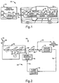
- a remote convenience vehicle system 10 in accordance with the present invention is schematically shown in Fig. 1, along with an associated vehicle 12.
- the system 10 described herein includes one or more remote transmitter units 14 that communicate, via an electromagnetic command signal 16, with a vehicle-mounted receiver/controller unit 18 to achieve remote control of at least one vehicle system.
- the receiver/controller unit is referred to simply as the receiver unit.
- each transmitter unit 14 can transmit any of a plurality of command signals 16 to the receiver unit 18.
- Each command signal 16 is a broadcast signal and conveys a security code and a message that requests performance of a certain vehicle function.
- the receiver unit Upon receipt of an authorized command signal 16 by the receiver unit 18, the receiver unit provides the function-request message to an appropriate vehicle system control means.
- An example of a vehicle system that has remotely controllable functions is a power door lock system that locks and unlocks one or more vehicle doors.
- Another example of a vehicle system that has remotely controllable functions is a trunk release system that releases a trunk latch mechanism.
- Yet another example of a remotely controllable vehicle function is what is referred to as a vehicle-find function. Specifically, the vehicle's horn and/or lights are actuated to identify the location of the vehicle for the transmitter unit operator (e.g., the vehicle owner), who is located at a distance from the vehicle. It will be appreciated that other embodiments of the present invention may have other remotely controlled functions (e.g., garage door opening, entry light activation).
- the transmitter unit 14 is a portable, hand-held unit.
- the transmitter unit 14 includes at least one manually operable pushbutton switch 20.
- the transmitter unit 14 includes at least one manually operable pushbutton switch 20.
- Each pushbutton switch 20 is connected to a signal source circuitry 22.
- Each actuation, or predefined series of actuations, of one of the pushbutton switches 20 corresponds to a predefined remote function request.
- the signal source circuitry 22 provides an appropriate electrical signal 24 to an antenna 26 of the transmitter unit 14.
- the antenna 26, in turn, emits, the signal 16.
- the signal 16 is a serially transmitted, digital signal that is broadcast.
- the signal 16 has a carrier frequency that is also referred to as the operating frequency of the transmitter unit 14.
- the carrier frequency is in the ultrahigh frequency (UHF) frequency range of the radio frequency (RF) spectrum.
- the carrier frequency is 315 MHz.
- the signal 16 is pulse-width modulated to represent the binary 1 and the binary 0.
- the remote transmitter unit 14 is designed to have a relatively low transmission power level.
- the remote transmitter unit 14 is operating at or below the power threshold for unlicensed transmission devices, as designated by the United States Federal Communications Commission (FCC).
- FCC United States Federal Communications Commission
- the receiver unit 18 it is noted as being desirable for the receiver unit 18 to receive the transmitted signal 16 for the scenario in which the transmitter unit 14 and the receiver unit 18 are spaced apart a relatively great distance.
- an antenna 28 of the receiver unit receives the transmitted signal 16.
- the antenna 28 outputs an electrical signal 30 to superheterodyne circuitry 32.
- the signal 30 has the same characteristics as the signal 16, in that the signal 30 has the same UHF frequency as the signal 16 and is pulse width modulated to convey the information contained within the signal 16.
- the superheterodyne circuitry 32 "converts" the UHF frequency associated with the transmitted signal 16 to an intermediate frequency (IF).
- An output signal 34 from the superheterodyne circuitry 32 is at the IF frequency and conveys the information of the signal 16 (i.e., the security code and message).
- the output signal 34 from the superheterodyne circuitry 32 must be at or very near a specific IF frequency.
- the IF frequency is related to a specific UHF frequency.
- the specific UHF frequency is referred to as the operating UHF frequency of the receiver unit 18.
- the operating UHF frequency of the receiver unit 18 must be substantially identical to the frequency of the signal 16. In other words, the operating UHF frequencies of the transmitter and receiver units 14, 18 must substantially match.
- the output signal 34 from the superheterodyne circuitry 32 is provided to automatic tuner circuitry 36.
- the automatic tuner circuitry 36 functions to automatically make an adjustment within the receiver unit 18, in accordance with the present invention.
- the operating frequency of the receiver unit is matched to that of the transmitted signal 16 (i.e., the tuner circuitry 36 automatically adjusts the operating frequency of the receiver unit 18 to "accept" the signal 16 at the frequency at which it was transmitted).
- the automatic tuner circuitry 36 operates such that the receiver unit 18 can discern the transmitted signal 16 from the remote transmitter unit 14 with a high level of sensitivity. Specifically, the automatic tuner circuitry 36 functions to focus the receiver unit's capabilities to a relatively narrow bandwidth, thus improving the receiver unit's sensitivity for receiving the relatively low power transmitted signal 16. Once the automatic tuner circuitry 36 adjusts the operating frequency of the receiver unit 18 to the frequency of the signal 16, the information contained within the received signal 16 is processed, via signal processing circuitry 38 to verify the security code and to accomplish the requested function.
- the superheterodyne circuitry 32 includes a front end amplifier 40 which receives the signal 30 output from the antenna 28.
- An output signal 42 of the amplifier 40 is provided as a first input to a mixer 44.
- a local or reference oscillator 46 provides an oscillating signal 48 at a reference frequency that is intended to be a selected value. In one example, the reference frequency is 314.555 MHz.
- the signal 48 provided by the reference oscillator 46 is a second input of the mixer 44.
- the mixer 44 combines the two input signals 42,48, and outputs a signal 50 having frequency component values that are at the sum and difference of the frequency values of the two input signals 42,48. In other words, the mixer 44 "beats" the first input signal 42 with the second input signal 48. The "difference frequency” value is the IF frequency. The “sum frequency” is ignored.
- the receiver unit 18 includes a buffer 52 and an amplifier 54 for handling the IF frequency signal 50 output from the mixer 44 along a path 56 toward the signal processing circuitry 38.
- the buffer 52 receives the signal 50 from the mixer 44, and provides an output 58.
- the amplifier 54 is downstream of the buffer, and provides an output 60, which is supplied to the path 56 toward the signal processing circuitry 38 at a node 62.
- the intermediate frequency is 455 kHz.
- the carrier frequency of the transmitted signal 16 may vary over a range away from its intended value.
- the intended transmitted frequency is at 315 MHz
- the actual frequency may vary +/- 100 kHz.
- the reference frequency of the oscillator signal 48 may vary because of various factors such as manufacturing tolerances, aging and temperature.
- the intermediate frequency output by the mixer 44 may vary quite a bit.
- the intermediate frequency may be 455 kHz +/- 200 kHz.
- the automatic tuner circuitry 36 includes a tunable bandpass filter 66 which has an adjustable bandpass range for "matching" the operating UHF frequency of the receiver unit 18 to the operating frequency of the transmitter unit 14 via selective passage of the IF frequency signal generated by the mixer 44. Specifically, the center frequency of the bandpass is adjusted until the operating frequency of the transmitter passes through the bandpass filter 66.
- the range of frequencies passed by the bandpass filter 66 is a relatively narrow range of IF frequencies.
- the bandpass filter 66 is interposed along the path 56 toward the signal processing circuitry 38.
- the bandpass filter 66 is located between the buffer 52 and the amplifier 54, such that the bandpass filter receives the signal 58 from the amplifier 54 and provides a filtered signal 68 to the amplifier 54.
- the automatic tuner circuitry 36 includes tuning control circuitry 70 and passage detector circuitry 72.
- the tuning control circuitry 70 provides a control signal 74 to the bandpass filter 66 to adjust or tune the bandpass of the tunable bandpass filter over a predetermined range of possible intermediate frequencies.
- the signal is automatically changed or varied to automatically vary the bandpass over the range. This adjustment process is repeated.
- the possible range of IF frequencies is repeatedly "swept" in search of an IF frequency signal created by the mixer 44 and output from the superheterodyne circuitry 32.
- the passage detector circuitry 72 is connected to the node 62 to receive the output 60 of the amplifier 54.
- the passage detector circuitry 72 monitors whether the bandpass filter 66 passes a particular IF frequency signal.
- a signal 76 that is indicative of the passage of a particular IF frequency signal through the bandpass filter 66 is provided to the turning control circuitry 70.
- the signal 76 causes the tuning control circuitry 70 to cease the adjustment and " lock" the bandpass filter onto the IF frequency which is passing through the bandpass filter.
- the passage detector circuitry 72 and the tuning control circuitry 70 include means for resetting and resuming the adjustment once the reception of the signal 16 is complete. Preferably, a short delay occurs before the reset/resume occurs, in order to await a subsequent signal 16.
- the bandpass of the bandpass filter 66 is dependent upon the voltage value of the control signal 74.
- the bandpass filter 66 has a voltage-controlled device and the control signal 74 is has a dc voltage value that is changed to adjust the bandpass.
- the bandpass filter 66 has a first resistor 82 connected to receive the output 58 of the buffer 52.
- the first resistor 82 is also connected to a node 84.
- a second resistor 86 is connected between the node 84 and electrical ground 88.
- a first capacitor 90 is connected between the node 84 and an output 92 of an amplifier 94.
- the output 92 of the amplifier 94 amplifies the output signal 68 from the bandpass filter 66.
- a third resistor 96 is connected between a first input 98 of the amplifier 94 and the amplifier output 92.
- a second input 100 of the amplifier 94 is connected to ground 88.
- Connected between the node 84 and the first amplifier input 98 is a capacitor circuit arrangement 102.
- the capacitor circuit arrangement 102 includes a second capacitor 104 of the bandpass filter 66.
- the second capacitor 104 is connected between the node 84 and the first amplifier input 98.
- the capacitor circuit arrangement 102 also includes a third capacitor 106 of the bandpass filter 66, and a varactor 108, which are in series between the node 84 and the first amplifier input 98.
- the third capacitor 106 and the varactor 108 are in parallel with the second capacitor 104.
- the control signal 74 from the tuning control circuitry 70 is provided as a control input to the varactor 108.
- a capacitance value of the varactor 108 is dependent upon the voltage of the control signal 74.
- the capacitance value C is dependent upon the capacitance of the varactor 108.
- Fig. 3 also shows optional capacitor 106' and varactor 108' (phantom connection shown), that are connected in series with each other, and that are connected in parallel with the capacitor 90.
- the varactor 108' is controlled by the control voltage signal 74.
- the capacitor 106' and varactor 108' help "balance" the bandpass filter 66, and their use is preferred.
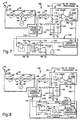
- Fig. 4 shows a first specific receiver unit embodiment of the invention.
- the receiver unit of Fig. 4 is designated 18A and illustrates first specific examples of the tuning control circuitry and the passage detector circuitry.
- structure that is identical to structure shown in Fig. 2 is identified by the same reference numerals.
- the tuning control circuitry and the passage detector circuitry have embodiment-specific structure and are identified by the alphanumeric designations 70A and 72A, respectively.
- the passage detector circuitry 72A includes a comparator 114.
- An output of the comparator 114 is the signal 76A.
- a first input 116 of the comparator 114 is connected to the output 60 of the amplifier 54.
- a second input 118 of the comparator 114 is connected to a reference node 120, which is in turn connected to a reference voltage source V cc .
- Connected between the first and second comparator inputs 116 and 118 is a first resistor 122.
- a second resistor 124 and a capacitor 126 are connected, in parallel, between the reference node 120 (i.e., the second comparator input 118) and ground 88.
- the comparator 114 monitors the output 60 of the amplifier 54, which has a noise component that is characterized as having a dc value with an ac value added to the dc value.
- the output 60 of the amplifier 54 consists of only the noise when the intermediate frequency created by the mixer 44 of the superheterodyne circuitry 32 does not pass through the bandpass filter 66. For this situation, the voltage at the first input 116 of the comparator 114 is less than the voltage at the second input 118 of the comparator 114.
- the comparator 114 outputs the signal 76A to have a digital "LOW" value.
- the comparator 114 When the intermediate frequency signal created by the mixer 44 of the superheterodyne circuitry 32 passes through the bandpass filter 66, the voltage of the first comparator input 116 exceeds the voltage at the second comparator input 118, and the comparator 114 outputs the signal 76A to have a digital "HIGH" value.
- the tuning control circuitry 70A of the embodiment shown in Fig. 4 controls the voltage of the control signal 74A provided to the tunable bandpass filter 66.
- the tuning control circuitry 70A includes voltage source scale circuitry 130 and a microprocessor 132.
- the voltage source scale circuitry 130 provides the control signal 74A, which has a voltage that has a stair-stepped characteristic. Specifically, the voltage of the control signal 74A is adjustable to one of a plurality of discrete voltage levels.
- the voltage source scale circuitry 130 is controlled by a control signal 134 provided by the microprocessor 132.
- a control signal 134 provided by the microprocessor 132.
- the possible range of the intermediate frequency that will pass through the bandpass filter 66 is predetermined to extend from a first or lower intermediate frequency IF 1 to a second or upper intermediate frequency IF 2 .
- the range IF 1 to IF 2 is greater than the bandwidth ⁇ f of the bandpass filter 66 at each adjustment setting of the bandpass filter. Hence, adjustment of the bandwidth ⁇ f is necessary to cover the range IF 1 to IF 2 .
- the microprocessor 132 provides the signal 134 to control the voltage source scale circuitry 130 to vary voltage of the control signal 74A.
- the bandpass filter 66 initially provides a bandwidth that includes IF 1 , and steps towards a bandwidth that includes IF 2 .
- the control by the microprocessor 132 to cause adjustment of the control signal 74A output by the voltage source scale circuitry 130 is continuously repeated so long as the tunable bandpass filter 66 does not pass an intermediate frequency signal.
- the microprocessor 132 causes the bandpass frequency adjustment to continue so long as the output signal 76A of the comparator 114 has a digital LOW value.
- the LOW signal value from the comparator 114 occurs while the receiver unit 18A is awaiting transmitted signal 16. Also, the LOW signal value from the comparator 114 occurs as a transmitted signal starts to be received and yet the tunable bandpass filter does not pass the IF frequency signal created by the mixer 44 of the superheterodyne circuitry 32. However, when the receiver unit 18A receives a transmitted signal 16, and the control signal 74A causes the bandpass filter 66 to pass a range of frequencies which include the intermediate frequency provided by the mixer 44, the output signal 76A of the comparator 114 goes HIGH. In response to the digital HIGH signal 76A, the microprocessor 132 controls the voltage source scale circuitry 130 to hold its control signal 74A at the present voltage level. This "locks" the bandpass of the bandpass filter 66 at a relatively narrow range, which permits passage of the intermediate frequency signal created by the mixer 44 of the superheterodyne circuitry 32.
- a greater number of voltage steps can be used to adjust the voltage level between the lowest and highest voltage levels. If a greater number of voltage levels are used, it is possible that the intermediate frequency signal created by the mixer 44 will pass through the bandpass filter 66 for more than one voltage level. For example, if the minimum required number of voltage levels (i.e., IF 2 - IF 1 / ⁇ f) is multiplied by N, the intermediate frequency signal will pass through the bandpass filter 66 for N voltage steps.
- the microprocessor 132 includes a function which stores information regarding which of the voltage steps are associated with passage of the intermediate frequency signal through the bandpass filter 66.
- the microprocessor 132 does not immediately "lock" the voltage source scale circuitry 130 upon the passage of the intermediate frequency signal through the bandpass filter 66 for a voltage step. Instead, the microprocessor 132 waits for the comparator output signal 76A to go LOW, and determines the average or center voltage level of all of the voltage levels which permitted passage of the intermediate frequency signal. Once the microprocessor 132 determines the center voltage level, the microprocessor provides the signal 134 instructing the voltage source scale circuitry 130 to locked the control signal 74A at the determined center voltage level. This allows for finer adjustment of the bandpass filter 66, to center the intermediate frequency in the bandpass of the bandpass filter.
- Fig. 5 illustrates an embodiment of the receiver unit that is designated 18B.
- the tuning control circuitry and the passage detector circuitry are identified by the alphanumeric designations 70B and 72B, respectively.
- structure that is identical to structure of the previously described embodiments is identified by the same reference numerals as used for the previous described embodiments.
- the receiver unit 18B of Fig. 5 is similar to the receiver unit 18A of Fig. 4, but shows an alternative to the comparator 114 of the passage detector circuitry 72A of the embodiment of Fig. 4.
- the embodiment in Fig. 5 includes an analog-to-digital (A/D) converter 140 as part of the passage detector circuitry 72B, which is connected to receive the output signal 60 of the amplifier 54.
- the A/D converter 140 provides a digital output signal 142 to a microprocessor 144.
- the voltage value of the signal 142 is indicative of the signal 68 output from the bandpass filter 66 (i.e., the voltage value is indicative of whether the IF frequency signal created by the mixer 44 of the superheterodyne circuitry 32 passes through the bandpass filter).
- the microprocessor 144 of Fig. 5 is different from the microprocessor 132 of Fig. 4.
- the microprocessor 144 is part of the tuning control circuitry 70B and part of the passage detection circuitry 72B.
- the microprocessor 144 of Fig. 5 monitors the digital signal 142 and compares the value of the digital signal 142 to a predetermined threshold value. When the voltage indicative value of the digital signal 142 is below the predetermined threshold, the microprocessor 144 controls the voltage source scale circuitry 130 to adjust the control signal 74B and cause adjustment of the bandpass of the bandpass filter 66.
- the microprocessor 144 When the value of the digital signal 142 exceeds the predetermined threshold value, the microprocessor 144 continues to cause adjustment of the bandpass, but also waits for the digital signal to reach a peak and beings to drop. The microprocessor 144 then controls the voltage control circuitry 130 to lock the control signal 74B at the peak voltage level.
- Fig. 6 illustrates an embodiment of the receiver unit that is designated 18C.
- the tuning control circuitry and the passage detector circuitry are identified by the alphanumeric designations 70C and 72C, respectively.
- structure that is identical to structure of the previously described embodiments is identified by the same reference numerals as used for the previous described embodiments.
- the embodiment shown in Fig. 6 is similar to the embodiment shown in Fig. 4, but has alternative elements for its passage detector circuitry 72C and its tuning control circuitry 70C.
- the passage detector circuitry 72C of Fig. 6 has a comparator circuit arrangement (i.e., comparator 114, resistors 122, 124, and capacitor 126) identical to the comparator circuit arrangement of the passage detector circuitry 72A of Fig. 4.
- the passage detector circuitry 72C (Fig. 6) has a NPN transistor 150.
- the output 152 of the comparator 114 is provided to a base terminal 154 of the NPN transistor 150.
- An emitter terminal 156 of the transistor 150 is connected to ground 88 and a collector terminal 158 is connected to line 160 extending the tuning control circuitry 70C.
- the line 160 to the tuning control circuitry 70C is disconnected from electrical ground 88.
- the line 160 to the tuning control circuitry 70C is connected to electrical ground 88.
- the signal provided on the line goes LOW when the IF frequency signal passes through the bandpass filter 66.
- the tuning control circuitry 70C includes a low frequency signal generator 162.
- the voltage of an output signal 164 of the signal generator 162 changes over a predetermined range. In one embodiment, the voltage "sweeps" through the predetermined range from a start voltage to an end voltage, and then repeats (i.e., the voltage has a saw-tooth pattern).
- the output signal 164 of the signal generator 162 is provided as an input to a switch box 166.
- the output of the signal generator 162 is connectable, via a switch 168 within the switch box 166, to a node 170.
- a resistor 172 is connected between an input of the switch box 166 and ground 88.
- the resistor 172 is connectable to the node 170, via a switch 174 of the switch box 166.
- the two switches 168 and 174 are represented in the drawings as schematic switches. However, the switches 168 and 174 may be any suitable switching devices.
- the switches 168 and 174 are configured such that they are both closed or opened concurrently.
- the concurrent control configuration is schematically shown in Fig. 6 by a dash line 176.
- a capacitor 178 is connected between the node 170 and ground 88.
- a unity gain voltage follower 180 is connected between the node 170 and the bandpass filter 66. The amplifier acts to isolate the node 170 from the input of the bandpass filter 66.
- the output of the voltage follower 180 is the control signal 74C.
- the switches 168 and 174 of the switch box 166 are closed, the voltage at the control node 170, and hence the voltage of the control signal 74C, follows the output signal 164 from the signal generator 162.
- the signal generator 162 and the resistor 172 are disconnected from the node 170.
- the voltage follower 180 continues to qutput the control signal 74C, and the voltage value of the control signal 74C stays constant for a period of time.
- the input impedance of the voltage follower 180 and the capacitor 178 define a RC circuit.
- the input impedance of the voltage follower is high, and thus, the time constant of the RC circuit is relatively large.
- the voltage of the control signal 74C stays constant due to the large time constant.
- the switches 168 and 174 of the switch box 166 are controlled via a signal 182 from a monostable multivibrator 184.
- the multivibrator 184 has an input terminal 186 connected to the line 160 extending to the collector terminal 158 of the NPN transistor 150.
- the input terminal 186 of the multivibrator 184 is connected to ground 88 (i.e., the voltage at the input terminal goes LOW).
- the connection of the input terminal 186 to ground is referred to as a wake-up signal.
- the signal 182 Prior to the multivibrator 184 receiving the wake-up signal, the signal 182 causes the switches to be closed. In response to the wake-up signal, the multivibrator 184 provides the signal such that the switches 168 and 174 are opened.
- the switches 168 and 174 are held open for a period of time, via the signal 182 from the multivibrator 184.
- the period of time is predetermined.
- the switches 168 and 174 are again closed, and adjustment of the voltage of the control signal 74C resumes.
- Fig. 7 illustrates an embodiment of the receiver unit that is designated 18D.
- the tuning control circuitry and the passage detector circuitry are identified by the alphanumeric designations 70D and 72D, respectively.
- structure that is identical to structure of the previously described embodiments is identified by the same reference numerals as used for the previous described embodiments.
- the embodiment shown in Fig. 7 is similar to the embodiment shown in Fig. 6, but has alternative stricture for its tuning control circuitry 70D. Specifically, the embodiment of Fig. 7 has a microprocessor 190 instead of the multivibrator 184 of the embodiment of Fig. 6. An input terminal 192 of the microprocessor 190 is connected to the line 160 extending from the collector terminal 158 of the NPN transistor 150. The microprocessor 190 is connected to provide a control signal 194 as an input to the switch box for controlling the switches 168 and 174.
- the output of the comparator goes HIGH and the transistor turns ON.
- the input terminal 192 is connected to ground through the transistor 150.
- the microprocessor 190 monitors the voltage at the terminal 192.
- the "grounding" of the terminal 192 provides a "wakeup" signal for the microprocessor 190.
- the microprocessor 190 provides the signal 194 such that the switches 168 and 174 of the switch box 166 are opened.
- the switches 168 and 174 are held open while the terminal 192 is grounded (i.e., while the IF frequency signal 50 created by the mixer 44 passes through the bandpass filter 66).
- the intermediate frequency signal generated by the mixer 44 ceases.
- the output of the comparator 114 goes LOW and the transistor 150 turns OFF.
- the terminal 192 of the microprocessor 190 is disconnected from ground 88.
- the microprocessor waits for a predetermined delay time and then provides the signal such that the switches 168 and 174 close.
- the adjustment of the control signal 74C resumes.
- the receiver unit 18D is ready to lock-in on the next transmitted signal 16.
- Fig. 8 illustrates an embodiment of the receiver unit that is designated 18E.
- the tuning control circuitry and the passage detector circuitry are identified by the alphanumeric designations 70E and 72E, respectively.
- structure that is identical to structure of the previously described embodiments is identified by the same reference numerals as used for the previous described embodiments.
- the embodiment shown in Fig. 8 is similar to the embodiment shown in Fig. 7. Specifically, the passage detector circuitry of the embodiment shown in Fig. 8 is identical to the embodiment of Fig. 7. However, the tuning control circuitry 70E of the embodiment of Fig. 8 is different.
- the tuning control circuitry 70E includes a low frequency signal generator 202, which provides an oscillating output signal 204, similar to the signal generator 162 of the embodiment of Fig. 6.
- the output signal 204 is provided, via a first switch 206 of a switch box 208, as the control signal 74E for the bandpass filter 66.
- the first switch 206 is closed, the bandpass of the bandpass filter 66 is changed based upon the voltage provided by the signal generator 202.
- the output signal 204 of the signal generator 202 is also provided to a microprocessor 210 of the tuning control circuitry 70E.
- the microprocessor 210 monitors the voltage of the output signal 204.
- An output 212 of the microprocessor 210 is a digital signal indicative of the voltage of the signal generator output signal 204.
- the digital output signal 212 from the microprocessor 210 is provided to a digital-to-analog (D/A) converter 214.
- An analog signal 216 provided by the D/A converter 214 has a voltage dependent upon the digital signal 212 provided by the microprocessor 210.
- the output of the D/A converter 214 is connected to a second switch 218 of the switch box 208.
- the first and second switches 206, 218 are configured such that when the first switch 206 is closed, the second switch 218 is opened, and when the first switch 206 is opened, the second switch 218 is closed.
- the output signal 216 is the control signal 74E for the bandpass filter 66 when the second switch 218 is closed.
- the microprocessor 210 has an input terminal 222 connected to the line 160 extending to the collector terminal 158 of the transistor 150. Also, delay circuitry 224 is connected to the line 160. The delay circuitry 224 provides a control signal 226 to the switch box 208 to control operation of the switches 206, 218. When the transistor 150 is OFF (i.e., an IF frequency signal created by the mixer of the superheterodyne circuitry 32 is not passing through the bandpass filter 66 and the comparator output is LOW), the delay circuitry 224 provides the signal 226 such that the first switch 206 is closed and the second switch 218 is open. The bandpass of the bandpass filter 66 is progressively adjusted via the control signal 74E provides by the signal generator 202.
- the output of the comparator 114 goes HIGH and the transistor 150 turns ON.
- the wakeup signal is provided both to the delay circuitry 224 and the microprocessor 210.
- the microprocessor 210 "locks" the digital value provided to the D/A converter 214. Accordingly, the voltage of the output signal 216 remains at a constant value.
- the delay circuitry 224 provides the signal 226 such that the switches are toggled.
- the first switch 206 of the switch box 208 is opened and the second switch 218 is closed.
- the signal generator 202 is disconnected from the bandpass filter 66 and the D/A converter 214 is connected to provide the control signal 74E to the bandpass filter 66. Accordingly, the bandpass of the bandpass filter 66 is held constant.
- the delay circuitry 224 provides the signal 226 such that the first switch 206 closes and the second switch 218 opens. Also, the microprocessor 210 is reset such that the microprocessor resumes providing the digital signal 212 to the D/A converter that is indicative of the voltage of the output signal 204 of the signal generator 202.
- the invention relates to a receiver/controller apparatus for a remote convenience system, said apparatus being responsive to a function request transmitted by a portable transmitter for controlling performance of an associated function, said apparatus comprising: means for receiving a signal, transmitted from the transmitter, which has a RF frequency, at an unknown value within a range of values, and which conveys a message that contains the function request, and for providing a RF signal having the RF frequency and conveying the message; means for providing a reference frequency signal; and means for mixing the RF signal with the reference frequency signal to provide an intermediate frequency signal conveying the message, the frequency of the intermediate frequency signal being at an unknown value within a known range of values.
Landscapes
- Engineering & Computer Science (AREA)
- Computer Hardware Design (AREA)
- Microelectronics & Electronic Packaging (AREA)
- Selective Calling Equipment (AREA)
Claims (30)
- Eine Empfangs-/Steuervorrichtung für ein Fernsteuerungsbequemlichkeitssystem, wobei die Vorrichtung auf eine Funktionsanfrage anspricht, die durch eine tragbare Sendevorrichtung zum Steuern von Leistungsfähigkeit einer assoziierten Funktion übertragen wird, wobei die Vorrichtung Folgendes aufweist:Mittel (28) zum Empfangen eines von der Sendevorrichtung übertragenen Signals (16), das eine Hochfrequenz-(HF)-frequenz besitzt, und zwar von einem unbekannten Wert innerhalb eines Wertebereichs, und die eine Nachricht überträgt, die die Funktionsanfrage enthält, und zum Liefern eines HF-Signals, das die HF-Frequenz besitzt und die Nachricht überträgt;Mittel (46) zum Liefern eines Bezugs- bzw. Referenzfrequenzsignals;Mittel (47) zum Mischen des HF-Signals mit dem Referenzfrequenzsignal zum Liefern eines Zwischenfrequenzsignals, das die Nachricht überträgt, wobei die Frequenz des Zwischenfrequenzsignals einen unbekannten Wert innerhalb eines bekannten Wertebereichs besitzt;Mittel (66) zum Bandpassfiltern des Zwischenfrequenzsignals, um einen Frequenzwertebereich durchzulassen, der kleiner als der bekannte Zwischenfrequenzwertebereich ist, wobei der Bandpassbereich eine Mittelfrequenz besitzt;Mittel (70) zum automatischen Einstellen der Mittelfrequenz des Bandpassbereichs der Mittel zur Bandpassfilterung, um den Bandpassbereich über den Zwischenfrequenzbereich zu verändern;Mittel (72) zum Abfühlen des Zwischenfrequenzsignals, das durch die Mittel zur Bandpassfilterung hindurchgeht, und zum automatischen Beenden der Einstellung der Mittelfrequenz des Bandpassbereichs ansprechend darauf;Mittel (38) zum Unterscheiden der Nachricht von dem gefilterten Zwischenfrequenzsignal; undMittel zum Steuern der Leistungsfähigkeit der angefragten Funktion der Nachricht.
- Eine Vorrichtung nach Anspruch 1, wobei die Mittel (66) zum Bandpassfiltern eine Schaltung umfassen, die eine einstellbare elektrische Charakteristik besitzt, die gesteuert ist mittels eines angelegten Spannungssignals.
- Eine Vorrichtung nach Anspruch 2, wobei die Schaltung einen Varactor (104) umfasst.
- Eine Vorrichtung nach Anspruch 1, wobei die Mittel (72) zum Abfühlen eine Vergleichsschaltung umfassen zum Vergleichen eines Wertes einer elektrischen Charakteristik einer Signalausgangsgröße von den Mitteln zum Bandpassfiltern (66) mit einem Referenzwert und zum Bestimmen, ob der Wert der elektrischen Charakteristik den Referenzwert überschreitet.
- Eine Vorrichtung nach Anspruch 1, wobei die Mittel zum Bandpassfiltern (66) ein analoges Signal ausgeben, wobei die Mittel zum Abfühlen Mittel umfassen zum Umwandeln des analogen Signals zu einem digitalen Signal, das einen digitalen Wert besitzt, wobei die Mittel zum Abfühlen ebenfalls Mittel umfassen zum Vergleichen des digitalen Wertes mit einem Referenzwert und zum Bestimmen, ob der digitale Wert des digitalen Signals den Referenzwert überschreitet.
- Eine Vorrichtung nach Anspruch 1, wobei die Mittel (70) zum automatischen Einstellen Mittel umfassen zum Liefern eines Signals mit einem Spannungsniveau aus einer Vielzahl von diskreten Spannungsniveaus und Mittel zum Steuern der Mittel zum Liefern eines Signals, um die Signalspannung innerhalb der Spannungsniveaus zu ändern.
- Eine Vorrichtung nach Anspruch 1, wobei die Mittel (70) zum automatischen Einstellen Mittel (162) umfassen zum Erzeugen eines Oszillationssignals und Mittel zum Liefern des Oszillationssignals an die Mittel zum Bandpassfiltern, um den Bandpassbereich einzustellen.
- Eine Vorrichtung nach Anspruch 7, wobei die Mittel (162) zum Liefern des Oszillationssignals an die Mittel zur Bandpassfilterung (66) Schaltmittel umfassen zum selektiven Durchlassen des Oszillationssignals zu den Mittel zum Bandpassfiltern.
- Eine Vorrichtung nach Anspruch 8, wobei die Mittel (70) zum automatischen Einstellen einen Multivibrator zum Steuern der Schaltmittel umfassen.
- Eine Vorrichtung nach Anspruch 8, wobei die Mittel (70) zum automatischen Einstellen eine Mikroprozessor zum Steuern der Schaltmittel umfassen.
- Eine Vorrichtung nach Anspruch 8, wobei die Schaltmittel erste und zweite Zustände besitzen, wobei die Vorrichtung ferner eine eine RC-Konstante besitzende Schaltung umfasst, die mit dem Oszillator (162) verbunden ist, wenn sich die Schaltmittel in dem ersten Zustand befinden, und nicht verbunden ist mit dem Oszillator, wenn sich die Schaltmittel in dem zweiten Zustand befinden, wobei der Oszillator den Bandpass der Mittel (66) zur Bandpassfilterung steuert, wenn sich die Schaltmittel in dem ersten Zustand befinden, und die Schaltung, die die RC-Konstante besitzt, den Bandpass der Mittel zum Bandpassfiltern steuert, wenn sich die Schaltmittel in dem zweiten Zustand befinden.
- Eine Vorrichtung nach Anspruch 8, wobei die Schaltmittel erste und zweite Zustände besitzen, wobei die Vorrichtung ferner Mittel umfasst zum Überwachen einer elektrischen Charakteristik des Oszillationssignals, Mittel zum Bestimmen des Wertes der überwachten Charakteristik, assoziiert mit dem Durchgang des Zwischenfrequenzsignals durch die Mittel (66) zum Bandpassfiltern, und Mittel zum Liefern eines Signals, das eine Anzeige bildet für den bestimmten Charakteristikwert, wobei das Oszillationssignal verwendet wird, um den Bandpass der Mittel (66) zum Bandpassfiltern zu steuern, wenn die Schaltmittel sich in dem ersten Zustand befinden und wobei das Signal, das eine Anzeige für den bestimmten Charakteristikwert bildet, verwendet wird, um den Bandpass der Mittel (66) zum Bandpassfiltern zu steuern, wenn die Schaltmittel sich in dem zweiten Zustand befinden.
- Eine Vorrichtung nach Anspruch 1, wobei die Mittel (70) zum automatischen Einstellen Mittel umfassen zum Einstellen des Bandpasses auf einen Bandpassbereich innerhalb einer Vielzahl von diskreten Bandpassbereichen.
- Eine Vorrichtung nach Anspruch 13, wobei mindestens zwei aus der Vielzahl von Bandpassbereichen Überlappungsteile besitzen, wobei die Vorrichtung Mittel umfasst zum Bestimmen eines Bandpassbereichs für die Mittel (66) zum Bandpassfiltern, dann wenn die Zwischenfrequenz in den Überlappungsteilen einer Vielzahl der Bandpassbereiche liegt.
- Ein Fernsteuerungsbequemlichkeitsystem zum Fernsteuern der Leistungsfähigkeit einer Funktion, wobei das System Folgendes aufweist: tragbare Sendermittel für Fernsteuerungsanfragen, die Mittel umfassen zum Übertragen eines HF-Signals, das eine Nachricht überträgt, die eine Funktionsanfrage enthält, wobei die Frequenz des HF-Signals einen unbekannten Wert innerhalb eines Bereiches von Werten besitzt; und Empfänger/Steuermittel zum Empfangen von Fernsteueranfragen und zum Steuern der Leistungsfähigkeit der angefragten Funktion, die Mittel (28) umfassen zum Empfangen des Signals (16), das von den Sendermittel übertragen wird und zum Liefern eines HF-Signals, das eine HF-Frequenz besitzt und die Nachricht überträgt, Mittel (46) zum Liefern eines Referenzfrequenzsignals, Mittel zum Mischen des HF-Signals mit dem Referenzfrequenzsignal, um ein Zwischenfrequenzsignal vorzusehen, das die Nachricht überträgt, wobei die Frequenz des Zwischenfrequenzsignals ein unbekannten Wert in einem bekannten Bereich von Werten besitzt, Mittel (66) zum Bandpassfiltern des Zwischenfrequenzsignals, um einen Bereich von Frequenzwerten durchzulassen, der kleiner ist als der bekannte Bereich von Zwischenfrequenzwerten, wobei der Bandpassbereich eine Mittelfrequenz besitzt, Mittel (70) für automatisches Einstellen der Mittelfrequenz des Bandpassbereichs der Mittel zum Bandpassfiltern, um den Bandpassbereich über den Zwischenfrequenzbereich zu variieren bzw. zu verändern, Mittel (72) zum Abfühlen des Zwischenfrequenzsignals, das durch die Mittel (66) zum Bandpassfiltern hindurchgeht und zum automatischen Beenden der darauf ansprechenden Einstellung der Mittelfrequenz des Bandpassbereichs.
- Ein System nach Anspruch 15, wobei die Mittel (66) zum Bandpassfiltern eine Schaltung umfassen, die eine einstellbare, elektrische Charakteristik besitzt, die mittels eines angelegten Spannungssignals gesteuert wird.
- Ein System nach Anspruch 16, wobei die Schaltung einen Varactor (108) umfasst.
- Ein System nach Anspruch 15, wobei die Mittel zum Abfühlen (72) eine Vergleichsschaltung (114) umfassen zum Vergleichen eines Wertes einer elektrischen Charakteristik einer Signalausgangsgröße von den Mitteln zum Bandpassfiltern mit einem Referenzwert, und zum Bestimmen, ob der Wert der elektrischen Charakteristik den Referenzwert überschreitet.
- Ein System nach Anspruch 15, wobei die Mittel (66) zum Bandpassfiltern ein analoges Signal ausgeben, wobei die Mittel zum Abfühlen Mittel umfassen zum Umwandeln des analogen Signals zu einem digitalen Signal, das einen digitalen Wert besitzt, wobei die Mittel zum Abfühlen ebenfalls Mittel umfassen zum Vergleichen des digitalen Wertes mit einem Referenzwert und zum Bestimmen, ob der digitale Wert des digitalen Signals den Referenzwert überschreitet.
- Ein System nach Anspruch 15, wobei die Mittel (70) zum automatischen Einstellen Mittel umfassen zum Liefern eines Signals, das eines einer Vielzahl von diskreten Spannungsniveaus besitzt, und Mittel zum Steuern der Mittel zum Liefern eines Signals, um die Signalspannung innerhalb der Spannungsniveaus zu verändern.
- Ein System nach Anspruch 15, wobei die Mittel (70) zum automatischen Einstellen Mittel umfassen zum Erzeugen eines Oszillationssignals und Mittel zum Liefern des Oszillationssignals an die Mittel zum Bandpassfiltern, um den Bandpassbereich einzustellen.
- Ein System nach Anspruch 21, wobei die Mittel zum Liefern des Oszillationssignals an die Mittel (66) zum Bandpassfiltern Schaltmittel umfassen zum selektiven Durchlassen des Oszillationssignals zu den Mitteln zum Bandpassfiltern.
- Ein System nach Anspruch 22, wobei die Mittel (70) zum automatischen Einstellen eines Multivibrators zum Steuern der Schaltmittel umfassen.
- Ein System nach Anspruch 22, wobei die Mittel (70) zum automatischen Einstellen einen Mikroprozessor (190) zum Steuern der Schaltmittel umfassen.
- Ein System nach Anspruch 22, wobei die Schaltmittel (166) erste und zweite Zustände besitzen, wobei die Empfänger/Steuermittel ferner eine eine RC-Konstante besitzende Schaltung umfassen, die mit dem Oszillator verbunden ist, wenn sich die Schaltmittel in dem ersten Zustand befinden, und von dem Oszillator getrennt sind, wenn die Schaltmittel sich in dem zweiten Zustand befinden, wobei der Oszillator den Bandpass der Mittel zum Bandpassfiltern steuert, wenn die Schaltmittel sich in dem ersten Zustand befinden und wobei die Schaltung, die die RC-Konstante besitzt, den Bandpass der Mittel (66) zum Bandpassfiltern steuert, wenn die Schaltmittel sich in dem zweiten Zustand befinden.
- Ein System nach Anspruch 22, wobei die Schaltmittel erste und zweite Zustände besitzen, wobei die Empfänger/Steuermittel ferner Mittel umfassen zum Überwachen einer elektrischen Charakteristik des eine RC-Konstante besitzt, Mittel zum Bestimmen des Wertes der überwachten Charakteristik assoziiert mit dem Durchgang des Zwischenfrequenzsignals durch die Mittel zum Bandpassfiltern, und Mittel zum Liefern eines Signals, das eine Anzeige bildet für den bestimmten Charakteristikwert, wobei das Oszillationssignal verwendet wird, um den Bandpass der Mittel (66) zum Bandpassfiltern zu steuern, wenn die Schaltmittel sich in dem ersten Zustand befinden und wobei das Signal, das eine Anzeige bildet für den bestimmten Charakteristikwert, verwendet wird, um den Bandpass der Mittel zum Bandpassfiltern zu steuern, wenn die Schaltmittel sich in dem zweiten Zustand befinden.
- Ein System nach Anspruch 15, wobei die Mittel (70) zum automatischen Einstellen Mittel umfassen zum Einstellen des Bandpasses auf einen Bandpassbereich innerhalb einer Vielzahl von diskreten Bandpassbereichen.
- Ein System nach Anspruch 27, wobei mindestens zwei der Vielzahl von Bandpassbereichen Überlappungsteile besitzen, wobei die Vorrichtung Mittel umfasst zum Bestimmen eines Bandpassbereichs für die Mittel (66) zum Bandpassfiltern, wenn die Zwischenfrequenz in Überlappungsteilen der Vielzahl von Bandpassbereichen liegt.
- Ein Verfahren zum Empfangen einer Funktionsanfrage, die durch einen tragbaren Sender zum Steuern der Leistungsfähigkeit bzw. Performance einer Funktion übertragen wird, wobei das Verfahren Folgendes aufweist:Empfangen eines übertragenen Signals (16) von einem Sender, wobei das übertragene Signal eine HF-Frequenz besitzt mit einem unbekannten Wert in einem Bereich von Werten und eine Nachricht überträgt, die eine Funktionsanfrage enthält, und Liefern eines HF-Signals, das eine HF-Frequenz besitzt und die Nachricht überträgt;Liefern eines Referenzfrequenzsignals (46);Mischen (44) des HF-Signals mit dem Referenzfrequenzsignal, um ein Zwischenfrequenzsignal zu liefern, das die Nachricht überträgt, wobei die Frequenz des Zwischenfrequenzsignals einen unbekannten Wert in einem bekannten Bereich von Werten besitzt;Bandpassfiltern (66) des Zwischenfrequenzsignals, um einen Bereich von Frequenzwerten durchzulassen, die kleiner sind als der bekannte Bereich von Zwischenfrequenzwerten, wobei der Bandpassbereich eine Mittelfrequenz besitzt;automatisches Einstellen (70) der Mittelfrequenz des Bandpassbereichs für das Bandpassfiltern, um den Bandpassbereich über den Zwischenfrequenzbereich zu variieren;Abfühlen (72) des Zwischenfrequenzsignals, das bandpassgefiltert wird und automatisches Beenden der darauf ansprechenden Einstellung der Mittelfrequenz des Bandpassbereichs;Unterscheiden der Nachricht von dem gefilterten Zwischenfrequenzsignal; undSteuern der Performance der angefragten Funktion der Nachricht.
- Ein Verfahren zur Fernsteuerperformance einer Funktion, wobei das Verfahren Folgendes aufweist:Übertragen eines HF-Signals (16), das eine Nachricht überträgt, die eine Funktionsanfrage enthält, wobei die Frequenz des HF-Signals einen unbekannten Wert in einem bekannten Bereich von Werten besitzt;Empfangen des übertragenen HF-Signals (32) und Liefern eines HF-Signals, das die HF-Frequenz besitzt und die Nachricht überträgt;Liefern eines Referenzfrequenzsignals (46);Mischen (44) des HF-Signals mit dem Referenzfrequenzsignal zum Liefern eines Zwischenfrequenzsignals, das die Nachricht überträgt, wobei die Frequenz des Zwischenfrequenzsignals einen unbekannten Wert in einem bekannten Bereich von Werten besitzt;Bandpassfiltern (66) des Zwischenfrequenzsignals, um einen Bereich von Frequenzwerten durchzulassen, die kleiner sind als der bekannte Bereich von Zwischenfrequenzwerten, wobei der Bandpassbereich eine Mittelfrequenz besitzt;automatisches Einstellen (70) der Mittelfrequenz des Bandpassbereichs für das Bandpassfiltern, um den Bandpassbereich über den Zwischenfrequenzbereich zu variieren;Abfühlen (72) des Zwischenfrequenzsignals, das bandpassgefiltert wird und automatisches Beenden der darauf ansprechenden Einstellung der Mittelfrequenz des Bandpassbereichs;Unterscheiden der Nachricht von dem gefilterten Zwischenfrequenzsignal; undSteuern der Performance der angefragten Funktion der Nachricht.
Applications Claiming Priority (2)
| Application Number | Priority Date | Filing Date | Title |
|---|---|---|---|
| US09/007,899 US5926752A (en) | 1998-01-15 | 1998-01-15 | Apparatus and method for remote convenience message transmission and control with a tunable filter receiver |
| US7899 | 1998-01-15 |
Publications (2)
| Publication Number | Publication Date |
|---|---|
| EP0930705A1 EP0930705A1 (de) | 1999-07-21 |
| EP0930705B1 true EP0930705B1 (de) | 2004-09-15 |
Family
ID=21728707
Family Applications (1)
| Application Number | Title | Priority Date | Filing Date |
|---|---|---|---|
| EP99100654A Expired - Lifetime EP0930705B1 (de) | 1998-01-15 | 1999-01-14 | Vorrichtung und Verfahren zur Übertragung und Fernsteuerung unter Verwendung eines Empfängers mit abstimmbarem Filter |
Country Status (3)
| Country | Link |
|---|---|
| US (1) | US5926752A (de) |
| EP (1) | EP0930705B1 (de) |
| DE (1) | DE69920066D1 (de) |
Families Citing this family (15)
| Publication number | Priority date | Publication date | Assignee | Title |
|---|---|---|---|---|
| US6266522B1 (en) * | 1998-02-04 | 2001-07-24 | Ericsson Inc. | Apparatus and methods for tuning bandpass filters |
| AU1794400A (en) * | 1998-12-22 | 2000-07-12 | Hi-Key Limited | A receiver and a variable frequency signal generating circuit for the receiver |
| US6865375B1 (en) * | 1999-02-24 | 2005-03-08 | Legerity, Inc. | Method and apparatus for locating a synchronization signal |
| DE19908855A1 (de) * | 1999-03-01 | 2000-09-07 | Delphi Tech Inc | Rundfunkempfangsvorrichtung und Verfahren zum Steuern einer Rundfunkempfangsvorrichtung |
| US6392592B1 (en) * | 1999-09-30 | 2002-05-21 | Siemens Automotive Corporation | Hand held car locator |
| US6532360B1 (en) | 1999-12-14 | 2003-03-11 | M. Bennett Shaffer | Mobile security system with cellular transceiver, position reporting and remote actuation |
| US6763230B2 (en) * | 2001-02-20 | 2004-07-13 | Industrial Technology Research Institute | Frequency-lock filtering receiver |
| US6898419B1 (en) * | 2001-04-30 | 2005-05-24 | Nortel Networks Corporation | Remotely adjustable bandpass filter |
| US7006797B1 (en) | 2001-05-21 | 2006-02-28 | Counter Technologies, Llc | Coherence frequency determining system and associated radio apparatus |
| US7190937B1 (en) * | 2001-05-21 | 2007-03-13 | Counter Technologies, Llc | Method for determining the frequency of a radio signal and monitoring communications with a radio receiver |
| FR2832874A1 (fr) * | 2001-11-27 | 2003-05-30 | Koninkl Philips Electronics Nv | Tuner comprenant un filtre selectif |
| US7383056B2 (en) * | 2003-12-15 | 2008-06-03 | Fujitsu Ten Limited | Processing apparatus, portable transmitter, and remote operation system |
| JP4553579B2 (ja) * | 2003-12-15 | 2010-09-29 | 富士通テン株式会社 | 携帯用送信機、処理装置、及び遠隔操作システム |
| CN101444023B (zh) * | 2006-05-11 | 2013-10-23 | 日本电气株式会社 | 发射设备、接收设备、广播接收系统和通信方法 |
| CZ304756B6 (cs) * | 2013-10-29 | 2014-09-24 | Quatro Partners S.R.O. | Univerzální ovládací pohotovostní zařízení |
Family Cites Families (25)
| Publication number | Priority date | Publication date | Assignee | Title |
|---|---|---|---|---|
| US2902598A (en) * | 1953-03-31 | 1959-09-01 | Radion Corp | Double conversion multi-band tuning unit |
| US2846573A (en) * | 1956-10-23 | 1958-08-05 | Rca Corp | Heterodyning receiving system |
| US3249876A (en) * | 1963-02-07 | 1966-05-03 | Gen Dynamics Corp | Precision tracking of electrically tuned circuits |
| US3496473A (en) * | 1966-11-14 | 1970-02-17 | Gen Dynamics Corp | Automatically tuned communications systems |
| US3473128A (en) * | 1966-12-20 | 1969-10-14 | Vari L Co Inc | Automatic ganging of superheterodyne radio frequency stages |
| US3665318A (en) * | 1970-03-18 | 1972-05-23 | Regency Electronics | Radio receiver |
| US3634700A (en) * | 1970-12-29 | 1972-01-11 | Gen Electric | Bidirectional frequency scan system |
| FR2175671B1 (de) * | 1972-03-17 | 1977-04-01 | Trt Telecom Radio Electr | |
| US3873924A (en) * | 1972-11-02 | 1975-03-25 | Masco Corp | Signal-seeking radio receivers |
| US3824475A (en) * | 1973-02-01 | 1974-07-16 | Tennelec | Scanning radio receiver |
| CA1055625A (en) * | 1974-02-21 | 1979-05-29 | Kazuyoshi Tsukamoto | Indicating device for tuning apparatus |
| US3987400A (en) * | 1974-11-04 | 1976-10-19 | Masco Corporation Of Indiana | Multiband scanning radio receiver |
| US4011515A (en) * | 1975-05-23 | 1977-03-08 | General Electric Company | Tunable scanning radio receiver |
| US4264976A (en) * | 1978-03-17 | 1981-04-28 | Sanyo Electric Co., Ltd. | Tuning control apparatus for digital tuner |
| CA1173176A (en) * | 1979-06-04 | 1984-08-21 | Isao Fujimoto | Tuner apparatus |
| US4431990A (en) * | 1979-06-07 | 1984-02-14 | Keith H. Wycoff | Selective call communication receiver |
| JPS6143025A (ja) * | 1984-08-07 | 1986-03-01 | Nec Corp | 無線通信方式 |
| US4792993A (en) * | 1985-10-30 | 1988-12-20 | Capetronic (Bsr) Ltd. | TVRD receiver system with automatic bandwidth adjustment |
| GB2223896A (en) * | 1988-10-12 | 1990-04-18 | Philips Electronic Associated | Radio receivers |
| US5103314A (en) * | 1990-09-24 | 1992-04-07 | Thomson Consumer Electronics, Inc. | Color-coded system for selection of rf input terminals and associated scan lists |
| TW263640B (de) * | 1992-06-26 | 1995-11-21 | Philips Electronics Nv | |
| FR2706934B1 (de) * | 1993-06-21 | 1995-10-13 | Valeo Electronique | |
| DE4422906C2 (de) * | 1994-06-30 | 1996-12-05 | Telefunken Microelectron | Verfahren zum Betrieb eines Schließsystems für verschließbare Gegenstände |
| JPH08223667A (ja) * | 1995-02-17 | 1996-08-30 | Sanyo Electric Co Ltd | リモコン受信回路 |
| US6122493A (en) * | 1995-11-27 | 2000-09-19 | Sanyo Electric Co., Ltd. | Radio receiver having automatic broadcasting-station selecting function |
-
1998
- 1998-01-15 US US09/007,899 patent/US5926752A/en not_active Expired - Lifetime
-
1999
- 1999-01-14 DE DE69920066T patent/DE69920066D1/de not_active Expired - Lifetime
- 1999-01-14 EP EP99100654A patent/EP0930705B1/de not_active Expired - Lifetime
Also Published As
| Publication number | Publication date |
|---|---|
| DE69920066D1 (de) | 2004-10-21 |
| US5926752A (en) | 1999-07-20 |
| EP0930705A1 (de) | 1999-07-21 |
Similar Documents
| Publication | Publication Date | Title |
|---|---|---|
| US5926752A (en) | Apparatus and method for remote convenience message transmission and control with a tunable filter receiver | |
| US5699054A (en) | Trainable transceiver including a dynamically tunable antenna | |
| US6265988B1 (en) | Apparatus and method for remote convenience message transmission and control utilizing frequency diversity | |
| US5699055A (en) | Trainable transceiver and method for learning an activation signal that remotely actuates a device | |
| US5686903A (en) | Trainable RF transceiver | |
| US6384710B1 (en) | Apparatus and method for remote convenience message reception and control utilizing frequency diversity | |
| US6021319A (en) | Remote control system | |
| US5193210A (en) | Low power RF receiver | |
| US5722058A (en) | On-vehicle receiving system | |
| GB2315893A (en) | Trainable transmitter | |
| JP3181997B2 (ja) | 無線式エンジン始動装置 | |
| US5933074A (en) | Remote control transmitter broadcasting RF signals conveying plural information components | |
| US6373398B2 (en) | Automobile tuner system | |
| GB2315892A (en) | Multiple frequency transmitter | |
| JP3216586B2 (ja) | 車両用遠隔操作制御装置およびそのシステム | |
| US6472999B1 (en) | Apparatus and method for remote convenience message reception with signal strength determination | |
| US6466137B1 (en) | Apparatus and method for remote convenience message reception with adjustable pulse detection receiver portion | |
| GB2306031A (en) | Anti-theft device for a motor vehicle | |
| GB2300945A (en) | Trainable transmitter having variable gain control | |
| JP2000025572A (ja) | 無線式エンジン始動装置 | |
| JP3287277B2 (ja) | 車両用施錠制御装置 | |
| JP3248451B2 (ja) | 車載機器遠隔制御装置 | |
| EP1142112B1 (de) | Empfänger und frequenzveränderbarer signalgenerator dafür | |
| KR100466020B1 (ko) | 도어 잠금 장치의 거리 감지 회로 | |
| GB2322215A (en) | Fast scan trainable transmitter |
Legal Events
| Date | Code | Title | Description |
|---|---|---|---|
| PUAI | Public reference made under article 153(3) epc to a published international application that has entered the european phase |
Free format text: ORIGINAL CODE: 0009012 |
|
| AK | Designated contracting states |
Kind code of ref document: A1 Designated state(s): DE ES FR GB IT |
|
| AX | Request for extension of the european patent |
Free format text: AL;LT;LV;MK;RO;SI |
|
| 17P | Request for examination filed |
Effective date: 20000121 |
|
| AKX | Designation fees paid |
Free format text: DE ES FR GB IT |
|
| GRAP | Despatch of communication of intention to grant a patent |
Free format text: ORIGINAL CODE: EPIDOSNIGR1 |
|
| RAP1 | Party data changed (applicant data changed or rights of an application transferred) |
Owner name: TRW AUTOMOTIVE U.S. LLC |
|
| GRAS | Grant fee paid |
Free format text: ORIGINAL CODE: EPIDOSNIGR3 |
|
| GRAA | (expected) grant |
Free format text: ORIGINAL CODE: 0009210 |
|
| AK | Designated contracting states |
Kind code of ref document: B1 Designated state(s): DE ES FR GB IT |
|
| PG25 | Lapsed in a contracting state [announced via postgrant information from national office to epo] |
Ref country code: IT Free format text: LAPSE BECAUSE OF FAILURE TO SUBMIT A TRANSLATION OF THE DESCRIPTION OR TO PAY THE FEE WITHIN THE PRE;WARNING: LAPSES OF ITALIAN PATENTS WITH EFFECTIVE DATE BEFORE 2007 MAY HAVE OCCURRED AT ANY TIME BEFORE 2007. THE CORRECT EFFECTIVE DATE MAY BE DIFFERENT FROM THE ONE RECORDED.SCRIBED TIME-LIMIT Effective date: 20040915 Ref country code: FR Free format text: LAPSE BECAUSE OF FAILURE TO SUBMIT A TRANSLATION OF THE DESCRIPTION OR TO PAY THE FEE WITHIN THE PRESCRIBED TIME-LIMIT Effective date: 20040915 |
|
| REG | Reference to a national code |
Ref country code: GB Ref legal event code: FG4D |
|
| REF | Corresponds to: |
Ref document number: 69920066 Country of ref document: DE Date of ref document: 20041021 Kind code of ref document: P |
|
| PGFP | Annual fee paid to national office [announced via postgrant information from national office to epo] |
Ref country code: GB Payment date: 20041210 Year of fee payment: 7 |
|
| PG25 | Lapsed in a contracting state [announced via postgrant information from national office to epo] |
Ref country code: DE Free format text: LAPSE BECAUSE OF FAILURE TO SUBMIT A TRANSLATION OF THE DESCRIPTION OR TO PAY THE FEE WITHIN THE PRESCRIBED TIME-LIMIT Effective date: 20041216 |
|
| PG25 | Lapsed in a contracting state [announced via postgrant information from national office to epo] |
Ref country code: ES Free format text: LAPSE BECAUSE OF FAILURE TO SUBMIT A TRANSLATION OF THE DESCRIPTION OR TO PAY THE FEE WITHIN THE PRESCRIBED TIME-LIMIT Effective date: 20041226 |
|
| PGFP | Annual fee paid to national office [announced via postgrant information from national office to epo] |
Ref country code: FR Payment date: 20050105 Year of fee payment: 7 |
|
| PGFP | Annual fee paid to national office [announced via postgrant information from national office to epo] |
Ref country code: DE Payment date: 20050131 Year of fee payment: 7 |
|
| PLBE | No opposition filed within time limit |
Free format text: ORIGINAL CODE: 0009261 |
|
| STAA | Information on the status of an ep patent application or granted ep patent |
Free format text: STATUS: NO OPPOSITION FILED WITHIN TIME LIMIT |
|
| 26N | No opposition filed |
Effective date: 20050616 |
|
| EN | Fr: translation not filed | ||
| PG25 | Lapsed in a contracting state [announced via postgrant information from national office to epo] |
Ref country code: GB Free format text: LAPSE BECAUSE OF NON-PAYMENT OF DUE FEES Effective date: 20060114 |
|
| GBPC | Gb: european patent ceased through non-payment of renewal fee |
Effective date: 20060114 |