EP0930432A2 - Rotor blade form for Francis water turbine - Google Patents
Rotor blade form for Francis water turbine Download PDFInfo
- Publication number
- EP0930432A2 EP0930432A2 EP98120883A EP98120883A EP0930432A2 EP 0930432 A2 EP0930432 A2 EP 0930432A2 EP 98120883 A EP98120883 A EP 98120883A EP 98120883 A EP98120883 A EP 98120883A EP 0930432 A2 EP0930432 A2 EP 0930432A2
- Authority
- EP
- European Patent Office
- Prior art keywords
- impeller
- point
- blade
- trailing edge
- edge
- Prior art date
- Legal status (The legal status is an assumption and is not a legal conclusion. Google has not performed a legal analysis and makes no representation as to the accuracy of the status listed.)
- Granted
Links
Images


Classifications
-
- F—MECHANICAL ENGINEERING; LIGHTING; HEATING; WEAPONS; BLASTING
- F03—MACHINES OR ENGINES FOR LIQUIDS; WIND, SPRING, OR WEIGHT MOTORS; PRODUCING MECHANICAL POWER OR A REACTIVE PROPULSIVE THRUST, NOT OTHERWISE PROVIDED FOR
- F03B—MACHINES OR ENGINES FOR LIQUIDS
- F03B3/00—Machines or engines of reaction type; Parts or details peculiar thereto
- F03B3/12—Blades; Blade-carrying rotors
- F03B3/125—Rotors for radial flow at high-pressure side and axial flow at low-pressure side, e.g. for Francis-type turbines
-
- F—MECHANICAL ENGINEERING; LIGHTING; HEATING; WEAPONS; BLASTING
- F03—MACHINES OR ENGINES FOR LIQUIDS; WIND, SPRING, OR WEIGHT MOTORS; PRODUCING MECHANICAL POWER OR A REACTIVE PROPULSIVE THRUST, NOT OTHERWISE PROVIDED FOR
- F03B—MACHINES OR ENGINES FOR LIQUIDS
- F03B3/00—Machines or engines of reaction type; Parts or details peculiar thereto
- F03B3/12—Blades; Blade-carrying rotors
-
- Y—GENERAL TAGGING OF NEW TECHNOLOGICAL DEVELOPMENTS; GENERAL TAGGING OF CROSS-SECTIONAL TECHNOLOGIES SPANNING OVER SEVERAL SECTIONS OF THE IPC; TECHNICAL SUBJECTS COVERED BY FORMER USPC CROSS-REFERENCE ART COLLECTIONS [XRACs] AND DIGESTS
- Y02—TECHNOLOGIES OR APPLICATIONS FOR MITIGATION OR ADAPTATION AGAINST CLIMATE CHANGE
- Y02E—REDUCTION OF GREENHOUSE GAS [GHG] EMISSIONS, RELATED TO ENERGY GENERATION, TRANSMISSION OR DISTRIBUTION
- Y02E10/00—Energy generation through renewable energy sources
- Y02E10/20—Hydro energy
Definitions
- the invention relates to an impeller for a hydraulic fluid machine Francis-type, especially for a water turbine, pump turbine or Pump, comprising a housing that encloses the impeller as well appropriate connections for the water inflow and outflow.
- Such Machine generally further comprises a nozzle, which numerous Has blades, and the impeller or another stator ahead or is shoveled. For example, see US-A-4,496,282.
- the impeller of such a machine is subject to high operation Stresses caused by the acting forces. This applies in particular the connection points between the blades on the one hand and the Impeller base and the impeller rim on the other hand. Particularly large Stress peaks occur in the transition area between the blade and Impeller bottom on. This can cause cracks in the extreme loads lead mentioned places.
- the invention has for its object the impeller Flow machine, Francis-style, to design such that one for the service life of the machine is sufficient strength to the above neuralgic places is guaranteed without the fluidic optimal design is affected by this and that this necessary effort is as low as possible.
- the shovel if possible can be made thin.
- the relief element takes on the task of reorientation the stiffness in the blade, such that the maximum occurring Structural tension from the notch-sensitive connection area to one large area of the relief element is shifted at simultaneous lowering of the voltage level.
- the inventor has thus given a very simple measure.
- the surface element mentioned does not need to be thicker than the blade in the rest of the trailing edge area.
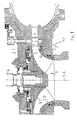
- the Francis turbine shown in FIG. 1 has an impeller 1 as the main elements on, a housing 2, a nozzle 3 and a shaft 4th
- the impeller comprises an impeller base 1.1, an impeller rim 1.2 and a variety of blades 1.3. Between the so-called turbine cover 2.1 and the impeller base 1.1 there is a wheel side space 5, and is between the impeller 1.2 and the housing 2 Wheel side compartment 6.
- the blade 1.3 has an entry edge 1.3.1 and an exit edge 1.3.2 on.
- the blade 1.3.2 points not far from the impeller bottom 1.1 a redirection.
- the course of the trailing edge 1.3.2 at a conventional blade is shown in dashed lines. Because of the The blade 1.3.1 has the course of the trailing edge 1.3.2 according to the invention an additional compared to conventional blades according to the invention Blade element 1.3.1, which is significantly larger than a conventional arcuate Transition is. In the present case, the blade element 1.3.1 is in the essentially triangular.
- Fig. 3 shows the conditions in detail. As you can see, it hits Part of the trailing edge 1.3.2 shown in dashed lines - as in conventional blades - at point A on the impeller bottom 1.1. In which The course according to the invention, however, meets the trailing edge 3.2 at point B. on the impeller bottom 1.1.
- the point of impact B is therefore one Bucket according to the invention opposite the point of impact A at a conventional shovel downstream.
- the course is as follows, in the direction of the impeller bottom 1.1 seen: First, there is a first rounding, starting from largely straight trailing edge. This first rounding goes over into a convex curvature. Then another rounding follows, the at point B gently opens into the inner contour of the impeller base 1.1.
- the additional blade element 1.3.1 according to the invention can be used with the Blade 1.3 be in one piece. This will be the case in particular if the entire impeller is cast. But it can also be attached. It can have the same thickness as the rest Trailing edge area 1.3.2. But it can also be a different one Have thickness. Furthermore, compared to the main part of the blade 1.3 be inclined so that a certain deflection of the flow in one or other direction.
- the distance between point A and C can be 0.1 to 0.3 of the total length of the outlet blade edge 1.3.2.
- the measure 0.2 has proven to be particularly advantageous. Deviations from that above and below are also possible.
Abstract
Description
Die Erfindung betrifft ein Laufrad für eine hydraulische Strömungsmaschine nach Francis-Bauart, insbesondere für eine Wasserturbine, Pumpturbine oder Pumpe, umfassend ein Gehäuse, das das Laufrad umschließt sowie entsprechende Anschlüsse für den Wasserzufluß und Abfluß. Eine solche Maschine umfaßt weiterhin im allgemeinen einen Leitapparat, der zahlreiche Schaufeln aufweist, und der dem Laufrad oder einem weiteren Leitrad vor- oder nachgeschaufelt ist. Als Beispiel wird auf US-A-4 496 282 verwiesen.The invention relates to an impeller for a hydraulic fluid machine Francis-type, especially for a water turbine, pump turbine or Pump, comprising a housing that encloses the impeller as well appropriate connections for the water inflow and outflow. Such Machine generally further comprises a nozzle, which numerous Has blades, and the impeller or another stator ahead or is shoveled. For example, see US-A-4,496,282.
Das Laufrad einer solchen Maschine unterliegt beim Betrieb hohen Beanspruchungen durch die einwirkenden Kräfte. Dies betrifft insbesondere die Anschlußstellen zwischen den Schaufeln einerseits und dem Laufradboden sowie dem Laufradkranz andererseits. Besonders große Spannungsspitzen treten im Übergangsbereich zwischen Schaufel und Laufradboden auf. Dies kann bei extremen Belastungen zu Rissen an den genannten Stellen führen.The impeller of such a machine is subject to high operation Stresses caused by the acting forces. This applies in particular the connection points between the blades on the one hand and the Impeller base and the impeller rim on the other hand. Particularly large Stress peaks occur in the transition area between the blade and Impeller bottom on. This can cause cracks in the extreme loads lead mentioned places.
Die üblicherweise getroffenen Maßnahmen hatten nur begrenzten Erfolg. So hat man beispielsweise die Schaufeldicke partiell oder insgesamt vergrößert. Es traten dennoch Risse auf. Außerdem wird hierdurch von der hydraulisch optimalen Gestaltung abgewichen.The measures usually taken have had limited success. So for example, the blade thickness has been increased partially or overall. However, cracks did appear. It also hydraulically deviated optimal design.
Der Erfindung liegt die Aufgabe zugrunde, das Laufrad einer Strömungsmaschine, nach Francis-Bauart, derart zu gestalten, daß eine für die Lebensdauer der Maschine ausreichende Festigkeit an den genannten neuralgischen Stellen gewährleistet ist, ohne daß die strömungstechnisch optimale Gestaltung hierdurch beeinträchtigt wird, und daß der hierzu notwendige Aufwand möglichst gering ist. So soll u.a. die Schaufel möglichst dünn gestaltet werden können. The invention has for its object the impeller Flow machine, Francis-style, to design such that one for the service life of the machine is sufficient strength to the above neuralgic places is guaranteed without the fluidic optimal design is affected by this and that this necessary effort is as low as possible. Among other things, the shovel if possible can be made thin.
Diese Aufgabe wird durch die Merkmale von Anspruch 1 gelöst.This object is solved by the features of
Demgemäß wird die einzelne Schaufel im Bereich der Austrittskante und zugleich im Bereich ihres Anschlusses an den Laufradboden durch ein kleines Flächenelement in stromabwärtiger Richtung vergrößert. Die Austrittskante der Schaufel, die normalerweise einen kontinuierlichen Verlauf aufweist, weist somit in einem gewissen Abstand vom Laufradboden eine Umlenkung auf, so daß der Endpunkt der Austrittskante im Bereich des Laufradbodens weiter stromabwärts liegt als dies normalerweise der Fall wäre.Accordingly, the individual blade in the area of the trailing edge and at the same time in the area of their connection to the wheel base by a small one Area element enlarged in the downstream direction. The trailing edge of the Bucket, which normally has a continuous course thus at a certain distance from the impeller bottom, so that the end point of the trailing edge continues in the area of the impeller bottom downstream than would normally be the case.
Das Entlastungselement übernimmt dabei die Aufgabe einer Umorientierung der Steifigkeit in der Schaufel, derart, daß die maximal auftretende Strukturspannung aus dem kerbempfindlichen Anschlußbereich auf einen großflächigen Bereich des Entlastungselementes verlagert wird, bei gleichzeitiger Absenkung des Spannungsniveaus.The relief element takes on the task of reorientation the stiffness in the blade, such that the maximum occurring Structural tension from the notch-sensitive connection area to one large area of the relief element is shifted at simultaneous lowering of the voltage level.
Damit hat der Erfinder eine höchst einfache Maßnahme angegeben. Das genannte Flächenelement braucht nicht dicker zu sein als die Schaufel im übrigen Austrittskantenbereich.The inventor has thus given a very simple measure. The surface element mentioned does not need to be thicker than the blade in the rest of the trailing edge area.
Was für den Übergang zwischen Schaufel und Laufradboden gilt, kann auch beim Übergang zwischen Schaufel und Laufradkranz angewandt werden. Jedoch sind die Spannungen im Übergangsbereich zum Laufradboden im allgemeinen größer und gefährlicher, so daß die erfindungsgemäße Maßnahme dort wichtiger ist.What applies to the transition between the blade and the impeller base can also do so be used at the transition between the blade and the impeller. However, the tensions in the transition area to the impeller base are in the generally larger and more dangerous, so that the invention Measure there is more important.
Die Erfindung ist anhand der Zeichnung näher erläutert. Darin ist im einzelnen folgendes dargestellt:
- Fig. 1
- zeigt eine Francis-Turbine in einem Axialschnitt.
- Fig. 2
- zeigt in einem Meridianschnitt einen Ausschnitt aus einem Laufrad einer Francis-Turbine.
- Fig. 3
- zeigt den Gegenstand von
Figur 1 in vergrößerter Darstellung.
- Fig. 1
- shows a Francis turbine in an axial section.
- Fig. 2
- shows a section of an impeller of a Francis turbine in a meridian section.
- Fig. 3
- shows the subject of Figure 1 in an enlarged view.
Die in Fig. 1 gezeigte Francis-Turbine weist als Hauptelemente ein Laufrad 1
auf, ein Gehäuse 2, einen Leitapparat 3 und eine Welle 4.The Francis turbine shown in FIG. 1 has an
Das Laufrad umfaßt einen Laufradboden 1.1, einen Laufradkranz 1.2 sowie
eine Vielzahl von Schaufeln 1.3. Zwischen dem sogenannten Turbinendeckel
2.1 und dem Laufradboden 1.1 befindet sich ein Radseitenraum 5, und
zwischen dem Laufradkranz 1.2 und dem Gehäuse 2 befindet sich ein
Radseitenraum 6.The impeller comprises an impeller base 1.1, an impeller rim 1.2 and
a variety of blades 1.3. Between the so-called turbine cover
2.1 and the impeller base 1.1 there is a
Aus Fig. 2 erkennt man wiederum den Laufradboden 1.1 einer Francis-Turbine, den Laufradkranz 1.2 sowie eine Schaufel 1.3.2 again shows the impeller bottom 1.1 of a Francis turbine, the impeller 1.2 and a blade 1.3.
Die Schaufel 1.3 weist eine Eintrittskante 1.3.1 und eine Austrittskante 1.3.2 auf.The blade 1.3 has an entry edge 1.3.1 and an exit edge 1.3.2 on.
Wie man ferner sieht, weist die Schaufel 1.3.2 nicht weit vom Laufradboden 1.1 eine Umlenkung auf. Der Verlauf der Austrittskante 1.3.2 bei einer herkömmlichen Schaufel ist gestrichelt dargestellt. Aufgrund des erfindungsgemäßen Verlaufes von Austrittskante 1.3.2 weist die Schaufel 1.3.1 gemäß der Erfindung gegenüber herkömmlichen Schaufeln ein zusätzliches Schaufelelement 1.3.1 auf, das deutlich größer als ein üblicher bogenförmiger Übergang ist. Im vorliegenden Falle ist das Schaufelelement 1.3.1 im wesentlichen dreieckig.As can also be seen, the blade 1.3.2 points not far from the impeller bottom 1.1 a redirection. The course of the trailing edge 1.3.2 at a conventional blade is shown in dashed lines. Because of the The blade 1.3.1 has the course of the trailing edge 1.3.2 according to the invention an additional compared to conventional blades according to the invention Blade element 1.3.1, which is significantly larger than a conventional arcuate Transition is. In the present case, the blade element 1.3.1 is in the essentially triangular.
Fig. 3 läßt die Verhältnisse im einzelnen erkennen. Wie man sieht, trifft der gestrichelt dargestellte Teil der Austrittskante 1.3.2 - so wie bei konventionellen Schaufeln - bei Punkt A auf den Laufradboden 1.1. Bei dem erfindungsgemäßen Verlauf hingegen trifft die Austrittskante 3.2 bei Punkt B auf den Laufradboden 1.1. Der Auftreffpunkt B liegt somit bei einer erfindungsgemäßen Schaufel gegenüber dem Auftreffpunkt A bei einer konventionellen Schaufel stromabwärts.Fig. 3 shows the conditions in detail. As you can see, it hits Part of the trailing edge 1.3.2 shown in dashed lines - as in conventional blades - at point A on the impeller bottom 1.1. In which The course according to the invention, however, meets the trailing edge 3.2 at point B. on the impeller bottom 1.1. The point of impact B is therefore one Bucket according to the invention opposite the point of impact A at a conventional shovel downstream.
Im einzelnen ist der Verlauf wie folgt, in Richtung auf den Laufradboden 1.1 gesehen: Zunächst erfolgt eine erste Ausrundung, ausgehend vom weitgehend geradlinigen Austrittskantenverlauf. Diese erste Ausrundung geht über in eine konvexe Krümmung. Sodann folgt eine weitere Ausrundung, die bei Punkt B sanft in die innere Kontur des Laufradbodens 1.1 einmündet.In detail, the course is as follows, in the direction of the impeller bottom 1.1 seen: First, there is a first rounding, starting from largely straight trailing edge. This first rounding goes over into a convex curvature. Then another rounding follows, the at point B gently opens into the inner contour of the impeller base 1.1.
Abweichend hiervon kann der erfindungsgemäße Austrittskantenverlauf 1.3.3 auch geradlinig sein. Ferner kann er generell, d.h. auf dem größten Teil seiner Erstreckung, auch leicht konkav verlaufen.Deviating from this, the trailing edge course 1.3.3 also be straightforward. Furthermore, in general, i.e. on most of it Extent, also slightly concave.
Das erfindungsgemäße zusätzliche Schaufelelement 1.3.1 kann mit der Schaufel 1.3 einteilig sein. Dies wird insbesondere dann der Fall sein, wenn das gesamte Laufrad im Gießverfahren hergestellt wird. Es kann aber auch angestückt werden. Es kann dieselbe Dicke haben wie der übrige Austrittskantenbereich 1.3.2. Es kann aber auch eine hiervon abweichende Dicke haben. Ferner kann es gegenüber dem Hauptteil der Schaufel 1.3 geneigt sein, so daß eine gewisse Umlenkung der Strömung in der einen oder anderen Richtung erfolgt.The additional blade element 1.3.1 according to the invention can be used with the Blade 1.3 be in one piece. This will be the case in particular if the entire impeller is cast. But it can also be attached. It can have the same thickness as the rest Trailing edge area 1.3.2. But it can also be a different one Have thickness. Furthermore, compared to the main part of the blade 1.3 be inclined so that a certain deflection of the flow in one or other direction.
Die Lage des Punktes C, bei welchem der erfindungsgemäße Längenabschnitt 1.3.3 seinen Ausgang nimmt, kann ebenfalls von Fall zu Fall unterschiedlich sein. So kann der Abstand zwischen Punkt A und C 0,1 bis 0,3 der Gesamtlänge der Austrittsschaufelkante 1.3.2 betragen. Das Maß 0,2 hat sich als besonders vorteilhaft erwiesen. Abweichungen von dem genannten Bereich nach oben und nach unten sind ebenfalls möglich. The location of point C at which the invention Longitudinal section 1.3.3 can also start from case to case be different. The distance between point A and C can be 0.1 to 0.3 of the total length of the outlet blade edge 1.3.2. The measure 0.2 has proven to be particularly advantageous. Deviations from that above and below are also possible.
Die bisherigen Erfahrungen zeigen, daß das Maß A - C wie auch das Maß B - C wenigstens 5% der in Strömungsrichtung gemessenen Schaufellänge betragen sollte. Nicht auszuschließen ist jedoch, daß auch ein noch geringeres Maß eine Verbesserung im Sinne der Lösung der gestellten Aufgabe bringt.Experience to date shows that measure A - C as well as measure B - C at least 5% of the blade length measured in the direction of flow should be. However, it cannot be ruled out that there is still one less of an improvement in the sense of solving the posed Task brings.
Claims (9)
Applications Claiming Priority (2)
| Application Number | Priority Date | Filing Date | Title |
|---|---|---|---|
| DE19801849A DE19801849B4 (en) | 1998-01-20 | 1998-01-20 | Impeller for a Francis type hydraulic fluid machine |
| DE19801849 | 1998-01-20 |
Publications (3)
| Publication Number | Publication Date |
|---|---|
| EP0930432A2 true EP0930432A2 (en) | 1999-07-21 |
| EP0930432A3 EP0930432A3 (en) | 2001-02-21 |
| EP0930432B1 EP0930432B1 (en) | 2004-04-21 |
Family
ID=7855055
Family Applications (1)
| Application Number | Title | Priority Date | Filing Date |
|---|---|---|---|
| EP98120883A Expired - Lifetime EP0930432B1 (en) | 1998-01-20 | 1998-11-04 | Rotor blade form for Francis water turbine |
Country Status (8)
| Country | Link |
|---|---|
| EP (1) | EP0930432B1 (en) |
| JP (1) | JPH11257199A (en) |
| KR (1) | KR19990067983A (en) |
| CN (1) | CN1100206C (en) |
| AT (1) | ATE264999T1 (en) |
| BR (1) | BR9805674A (en) |
| DE (2) | DE19801849B4 (en) |
| NO (1) | NO322075B1 (en) |
Cited By (4)
| Publication number | Priority date | Publication date | Assignee | Title |
|---|---|---|---|---|
| EP1712782A2 (en) * | 2005-04-07 | 2006-10-18 | General Electric Canada | Stress relief grooves for Francis turbine runner blades |
| EP1662136A3 (en) * | 2004-11-30 | 2011-04-27 | General Electric Canada | Runner for francis type hydraulic turbine |
| US10125737B2 (en) | 2012-12-19 | 2018-11-13 | Ge Renewable Technologies | Francis-type runner for a turbine, and energy conversion plant comprising such a runner |
| EP3683437A1 (en) * | 2019-01-18 | 2020-07-22 | GE Renewable Technologies | Hydroturbine runner blade local extension to avoid cavitation erosion |
Families Citing this family (5)
| Publication number | Priority date | Publication date | Assignee | Title |
|---|---|---|---|---|
| DE10210426A1 (en) * | 2002-03-09 | 2003-10-23 | Voith Siemens Hydro Power | Device for flow stabilization in hydraulic flow machines |
| AU2003281669A1 (en) | 2002-07-26 | 2004-02-16 | Bernd Gapp | Composite material |
| AT412496B (en) * | 2002-09-26 | 2005-03-25 | Va Tech Hydro Gmbh & Co | WHEEL OF A HYDRAULIC MACHINE |
| JP4094495B2 (en) * | 2003-06-16 | 2008-06-04 | 株式会社東芝 | Francis-type runner |
| CN101798983B (en) * | 2010-03-22 | 2011-12-21 | 东北师范大学 | Special turbine for self-variable-pitch bidirectional-flow ocean current power station |
Citations (1)
| Publication number | Priority date | Publication date | Assignee | Title |
|---|---|---|---|---|
| US4496282A (en) | 1982-05-06 | 1985-01-29 | Allis-Chalmers Corporation | Reversible two-stage hydraulic machine |
Family Cites Families (2)
| Publication number | Priority date | Publication date | Assignee | Title |
|---|---|---|---|---|
| DE322233C (en) * | 1915-10-30 | 1920-06-23 | Viktor Kaplan Dr Ing | Impeller for water turbines with wing-like blades |
| DE323190C (en) * | 1916-01-09 | 1920-07-17 | Robert Dubs | Blade for high-speed water turbines with a crescent-shaped meridional section |
-
1998
- 1998-01-20 DE DE19801849A patent/DE19801849B4/en not_active Expired - Fee Related
- 1998-11-04 EP EP98120883A patent/EP0930432B1/en not_active Expired - Lifetime
- 1998-11-04 DE DE59811236T patent/DE59811236D1/en not_active Expired - Lifetime
- 1998-11-04 AT AT98120883T patent/ATE264999T1/en active
- 1998-11-24 NO NO19985477A patent/NO322075B1/en not_active IP Right Cessation
- 1998-12-15 BR BR9805674-3A patent/BR9805674A/en not_active Application Discontinuation
- 1998-12-20 CN CN98126941A patent/CN1100206C/en not_active Expired - Lifetime
-
1999
- 1999-01-13 JP JP11006221A patent/JPH11257199A/en active Pending
- 1999-01-19 KR KR1019990001444A patent/KR19990067983A/en not_active Application Discontinuation
Patent Citations (1)
| Publication number | Priority date | Publication date | Assignee | Title |
|---|---|---|---|---|
| US4496282A (en) | 1982-05-06 | 1985-01-29 | Allis-Chalmers Corporation | Reversible two-stage hydraulic machine |
Cited By (6)
| Publication number | Priority date | Publication date | Assignee | Title |
|---|---|---|---|---|
| EP1662136A3 (en) * | 2004-11-30 | 2011-04-27 | General Electric Canada | Runner for francis type hydraulic turbine |
| EP1712782A2 (en) * | 2005-04-07 | 2006-10-18 | General Electric Canada | Stress relief grooves for Francis turbine runner blades |
| EP1712782A3 (en) * | 2005-04-07 | 2011-04-27 | General Electric Canada | Stress relief grooves for Francis turbine runner blades |
| US10125737B2 (en) | 2012-12-19 | 2018-11-13 | Ge Renewable Technologies | Francis-type runner for a turbine, and energy conversion plant comprising such a runner |
| EP3683437A1 (en) * | 2019-01-18 | 2020-07-22 | GE Renewable Technologies | Hydroturbine runner blade local extension to avoid cavitation erosion |
| WO2020148415A1 (en) * | 2019-01-18 | 2020-07-23 | Ge Renewable Technologies | Hydroturbine runner blade local extension to avoid cavitation erosion |
Also Published As
| Publication number | Publication date |
|---|---|
| BR9805674A (en) | 1999-12-07 |
| EP0930432B1 (en) | 2004-04-21 |
| CN1224116A (en) | 1999-07-28 |
| DE19801849A1 (en) | 1999-07-22 |
| CN1100206C (en) | 2003-01-29 |
| DE19801849B4 (en) | 2004-01-15 |
| KR19990067983A (en) | 1999-08-25 |
| EP0930432A3 (en) | 2001-02-21 |
| ATE264999T1 (en) | 2004-05-15 |
| NO985477L (en) | 1999-07-21 |
| JPH11257199A (en) | 1999-09-21 |
| DE59811236D1 (en) | 2004-05-27 |
| NO322075B1 (en) | 2006-08-14 |
| NO985477D0 (en) | 1998-11-24 |
Similar Documents
| Publication | Publication Date | Title |
|---|---|---|
| DE69920358T2 (en) | Bucket configuration for steam turbines | |
| DE69921320T2 (en) | TURBINENSTATORSCHAUFEL | |
| EP1632662B1 (en) | Turbomachine with bleeding | |
| DE3202855C1 (en) | Device for reducing secondary flow losses in a bladed flow channel | |
| DE102006057063B3 (en) | Stator stage of an axial compressor of a turbomachine with cross blades to increase efficiency | |
| DE102004054752A1 (en) | Blade of a flow machine with extended edge profile depth | |
| WO2007042522A1 (en) | Turbo-machine blade | |
| WO2007113149A1 (en) | Guide blade for turbomachinery, in particular for a steam turbine | |
| EP2275643B1 (en) | Engine blade with excess front edge loading | |
| WO2005106207A1 (en) | Compressor blade and compressor | |
| DE102005042115A1 (en) | Blade of a fluid flow machine with block-defined profile skeleton line | |
| EP0985098B1 (en) | Centrifugal pump with inflow guide device | |
| EP0930432B1 (en) | Rotor blade form for Francis water turbine | |
| DE102004029109A1 (en) | Francis turbine wheel blades have scalloped trailing edge profile delaying the onset of cavitation | |
| EP3571416B1 (en) | Shrouded centrifugal fan impeller with a periodically and asymmetrically shaped shroud | |
| DE3148995A1 (en) | Axial turbine | |
| DE102013020826A1 (en) | Radial compressor stage | |
| DE10307887A1 (en) | Centrifugal pump has blade whose region adjoining inlet edge has higher elasticity than remaining area in order to bend out from rest position through flow forces | |
| DE102010038277A1 (en) | Flow equalization slot | |
| WO2000057030A1 (en) | Turbomachine blade | |
| AT518291B1 (en) | IMPELLER BLADE OF A HYDRAULIC FLOWING MACHINE WITH ANTI-AVITATION BAR AND ANTI-AVITATION BAR FOR AN IMPELLER BLADE | |
| DE2014113A1 (en) | Impeller for radial turbines | |
| DE102008031781B4 (en) | Blade grille for a turbomachine and turbomachine with such a blade grille | |
| DE1930481A1 (en) | Blade or wing rotor | |
| EP3404211A1 (en) | Blade cascade segment for a turbine with contoured platform surface, corresponding blade cascade, blade channel, platform, turbine and aircraft engine |
Legal Events
| Date | Code | Title | Description |
|---|---|---|---|
| PUAI | Public reference made under article 153(3) epc to a published international application that has entered the european phase |
Free format text: ORIGINAL CODE: 0009012 |
|
| AK | Designated contracting states |
Kind code of ref document: A2 Designated state(s): AT CH DE ES FI FR GB IT LI NL SE |
|
| AX | Request for extension of the european patent |
Free format text: AL;LT;LV;MK;RO;SI |
|
| PUAL | Search report despatched |
Free format text: ORIGINAL CODE: 0009013 |
|
| AK | Designated contracting states |
Kind code of ref document: A3 Designated state(s): AT BE CH CY DE DK ES FI FR GB GR IE IT LI LU MC NL PT SE |
|
| AX | Request for extension of the european patent |
Free format text: AL;LT;LV;MK;RO;SI |
|
| 17P | Request for examination filed |
Effective date: 20010817 |
|
| AKX | Designation fees paid |
Free format text: AT CH DE ES FI FR GB IT LI NL SE |
|
| 17Q | First examination report despatched |
Effective date: 20030414 |
|
| GRAP | Despatch of communication of intention to grant a patent |
Free format text: ORIGINAL CODE: EPIDOSNIGR1 |
|
| GRAS | Grant fee paid |
Free format text: ORIGINAL CODE: EPIDOSNIGR3 |
|
| GRAA | (expected) grant |
Free format text: ORIGINAL CODE: 0009210 |
|
| AK | Designated contracting states |
Kind code of ref document: B1 Designated state(s): AT CH DE ES FI FR GB IT LI NL SE |
|
| PG25 | Lapsed in a contracting state [announced via postgrant information from national office to epo] |
Ref country code: NL Free format text: LAPSE BECAUSE OF FAILURE TO SUBMIT A TRANSLATION OF THE DESCRIPTION OR TO PAY THE FEE WITHIN THE PRESCRIBED TIME-LIMIT Effective date: 20040421 Ref country code: IT Free format text: LAPSE BECAUSE OF FAILURE TO SUBMIT A TRANSLATION OF THE DESCRIPTION OR TO PAY THE FEE WITHIN THE PRESCRIBED TIME-LIMIT;WARNING: LAPSES OF ITALIAN PATENTS WITH EFFECTIVE DATE BEFORE 2007 MAY HAVE OCCURRED AT ANY TIME BEFORE 2007. THE CORRECT EFFECTIVE DATE MAY BE DIFFERENT FROM THE ONE RECORDED. Effective date: 20040421 Ref country code: GB Free format text: LAPSE BECAUSE OF FAILURE TO SUBMIT A TRANSLATION OF THE DESCRIPTION OR TO PAY THE FEE WITHIN THE PRESCRIBED TIME-LIMIT Effective date: 20040421 Ref country code: FR Free format text: LAPSE BECAUSE OF FAILURE TO SUBMIT A TRANSLATION OF THE DESCRIPTION OR TO PAY THE FEE WITHIN THE PRESCRIBED TIME-LIMIT Effective date: 20040421 Ref country code: FI Free format text: LAPSE BECAUSE OF FAILURE TO SUBMIT A TRANSLATION OF THE DESCRIPTION OR TO PAY THE FEE WITHIN THE PRESCRIBED TIME-LIMIT Effective date: 20040421 |
|
| RAP1 | Party data changed (applicant data changed or rights of an application transferred) |
Owner name: VOITH SIEMENS HYDRO POWER GENERATION GMBH & CO |
|
| REG | Reference to a national code |
Ref country code: GB Ref legal event code: FG4D Free format text: NOT ENGLISH |
|
| REG | Reference to a national code |
Ref country code: CH Ref legal event code: EP |
|
| REF | Corresponds to: |
Ref document number: 59811236 Country of ref document: DE Date of ref document: 20040527 Kind code of ref document: P |
|
| PG25 | Lapsed in a contracting state [announced via postgrant information from national office to epo] |
Ref country code: SE Free format text: LAPSE BECAUSE OF FAILURE TO SUBMIT A TRANSLATION OF THE DESCRIPTION OR TO PAY THE FEE WITHIN THE PRESCRIBED TIME-LIMIT Effective date: 20040721 |
|
| PG25 | Lapsed in a contracting state [announced via postgrant information from national office to epo] |
Ref country code: ES Free format text: LAPSE BECAUSE OF FAILURE TO SUBMIT A TRANSLATION OF THE DESCRIPTION OR TO PAY THE FEE WITHIN THE PRESCRIBED TIME-LIMIT Effective date: 20040801 |
|
| NLV1 | Nl: lapsed or annulled due to failure to fulfill the requirements of art. 29p and 29m of the patents act | ||
| GBV | Gb: ep patent (uk) treated as always having been void in accordance with gb section 77(7)/1977 [no translation filed] |
Effective date: 20040421 |
|
| PG25 | Lapsed in a contracting state [announced via postgrant information from national office to epo] |
Ref country code: LI Free format text: LAPSE BECAUSE OF NON-PAYMENT OF DUE FEES Effective date: 20041130 Ref country code: CH Free format text: LAPSE BECAUSE OF NON-PAYMENT OF DUE FEES Effective date: 20041130 |
|
| PLBE | No opposition filed within time limit |
Free format text: ORIGINAL CODE: 0009261 |
|
| STAA | Information on the status of an ep patent application or granted ep patent |
Free format text: STATUS: NO OPPOSITION FILED WITHIN TIME LIMIT |
|
| EN | Fr: translation not filed | ||
| 26N | No opposition filed |
Effective date: 20050124 |
|
| REG | Reference to a national code |
Ref country code: CH Ref legal event code: PL |
|
| PGFP | Annual fee paid to national office [announced via postgrant information from national office to epo] |
Ref country code: DE Payment date: 20171121 Year of fee payment: 20 |
|
| PGFP | Annual fee paid to national office [announced via postgrant information from national office to epo] |
Ref country code: AT Payment date: 20171121 Year of fee payment: 20 |
|
| REG | Reference to a national code |
Ref country code: DE Ref legal event code: R071 Ref document number: 59811236 Country of ref document: DE |
|
| REG | Reference to a national code |
Ref country code: AT Ref legal event code: MK07 Ref document number: 264999 Country of ref document: AT Kind code of ref document: T Effective date: 20181104 |