EP0928852B1 - Holdown - Google Patents
Holdown Download PDFInfo
- Publication number
- EP0928852B1 EP0928852B1 EP98309425A EP98309425A EP0928852B1 EP 0928852 B1 EP0928852 B1 EP 0928852B1 EP 98309425 A EP98309425 A EP 98309425A EP 98309425 A EP98309425 A EP 98309425A EP 0928852 B1 EP0928852 B1 EP 0928852B1
- Authority
- EP
- European Patent Office
- Prior art keywords
- anchor
- connector
- members
- anchor receiving
- building structural
- Prior art date
- Legal status (The legal status is an assumption and is not a legal conclusion. Google has not performed a legal analysis and makes no representation as to the accuracy of the status listed.)
- Expired - Lifetime
Links
- 238000012360 testing method Methods 0.000 description 27
- 238000006073 displacement reaction Methods 0.000 description 21
- 238000007688 edging Methods 0.000 description 7
- 239000002023 wood Substances 0.000 description 7
- 238000005553 drilling Methods 0.000 description 6
- 239000002184 metal Substances 0.000 description 6
- 238000013461 design Methods 0.000 description 4
- 238000009432 framing Methods 0.000 description 4
- 229910000831 Steel Inorganic materials 0.000 description 3
- 238000005452 bending Methods 0.000 description 3
- 125000004122 cyclic group Chemical group 0.000 description 3
- 238000004519 manufacturing process Methods 0.000 description 3
- 238000000034 method Methods 0.000 description 3
- 238000010422 painting Methods 0.000 description 3
- 230000000087 stabilizing effect Effects 0.000 description 3
- 239000010959 steel Substances 0.000 description 3
- 238000012546 transfer Methods 0.000 description 3
- 238000003466 welding Methods 0.000 description 3
- 238000005520 cutting process Methods 0.000 description 2
- 238000009434 installation Methods 0.000 description 2
- 238000011160 research Methods 0.000 description 2
- 240000006108 Allium ampeloprasum Species 0.000 description 1
- 235000005254 Allium ampeloprasum Nutrition 0.000 description 1
- 238000006424 Flood reaction Methods 0.000 description 1
- 238000004873 anchoring Methods 0.000 description 1
- 230000001419 dependent effect Effects 0.000 description 1
- 230000003292 diminished effect Effects 0.000 description 1
- 238000003780 insertion Methods 0.000 description 1
- 230000037431 insertion Effects 0.000 description 1
- 239000000203 mixture Substances 0.000 description 1
- 230000000750 progressive effect Effects 0.000 description 1
- 238000004064 recycling Methods 0.000 description 1
Images


Classifications
-
- E—FIXED CONSTRUCTIONS
- E04—BUILDING
- E04B—GENERAL BUILDING CONSTRUCTIONS; WALLS, e.g. PARTITIONS; ROOFS; FLOORS; CEILINGS; INSULATION OR OTHER PROTECTION OF BUILDINGS
- E04B1/00—Constructions in general; Structures which are not restricted either to walls, e.g. partitions, or floors or ceilings or roofs
- E04B1/18—Structures comprising elongated load-supporting parts, e.g. columns, girders, skeletons
- E04B1/26—Structures comprising elongated load-supporting parts, e.g. columns, girders, skeletons the supporting parts consisting of wood
- E04B1/2604—Connections specially adapted therefor
- E04B2001/268—Connection to foundations
- E04B2001/2684—Connection to foundations with metal connectors
Definitions
- This invention relates to a connector for anchoring a first building structural member to a second building structural member.
- the connector works in conjunction with a separate anchor member that is received by or is attached to the second building structural member and with fasteners for attaching the connector to the first building structural member.
- framed walls can be attached to the foundation rather than merely rest on it; connections between the framed walls of each floor can be strengthened; and joists can be connected to both their headers and the walls that support the headers.
- One of the most common connectors designed for this application is called a holdown by the inventor. Holdowns are commonly used to anchor framed walls to the foundation.
- holdown connectors that work in conjunction with a separate anchor member and attach to only one face of the first building structural member - generally a vertically disposed stud - work in a common fashion.
- the anchor member attaches at the seat of the connector. This seat is connected to a back member.
- the back member attaches to the first building structural member.
- Most holdown connectors have one or more side members to increase the strength of the connector or to connect the seat member to the back.
- U.S. Patent No. 5,364,214, granted November 15, 1994 to Fazekas, Scott discloses a uni-directional slack adjuster incorporated into a holdown, tension rod or strap. The slack adjuster eliminates bolt slack to avoid vertical bolt play.
- the holdown connector of the present invention works in a similar fashion to most of the prior art holdowns, such that it is amenable to standard installation practices.
- the holdown connector of the present invention improves on the prior art by accommodating variations in the position of the anchor member parallel to the face of the first building structural member to which the holdown connector attaches.
- the holdown connector of the present invention also withstands high tension loads while being economical to produce.
- the present invention provides a connector as set forth in the appended claims.
- the object of the present invention is to provide a connector that better withstands tension forces than the prior art while still being economical to produce and install.
- a further object of the present invention is to provide a connector that accommodates variations in the position of the anchor member parallel to the face of the first building structural member to which the holdown connector attaches. This object is achieved by forming the connector with a wide space for receiving the anchor member.
- the object of making a holdown that is economical to produce is achieved by utilizing a design that can be formed from galvanized sheet metal on standard die press machinery, eliminating costly secondary operations such as painting and welding.
- the object of making a holdown that is easy to install is achieved by utilizing a design that is amenable to current building practices.
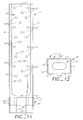
- a connector 1 for tying a first building structural member 2 to a second building structural member 3 in conjunction with fasteners 4 and an anchor member 5 constructed in accordance with the present invention, consists of a back member 6 formed to interface with the fasteners 4 for attaching the back member 6 to the first building structural member 2, a first side member 7 connected to the back member 6, a second side member 8 connected to the back member 6, and first and second anchor receiving members 9 and 10 .
- Both the first and second anchor receiving members 9 and 10 extend laterally between the first and second side members 7 and 8, and both the first and second anchor receiving members 9 and 10 are connected to the first and second side members 7 and 8, the first and second anchor receiving members 9 and 10 are disposed so that a space 11 exists between the first and second anchor receiving members 9 and 10 for receiving the anchor member 5 therethrough for attaching the connector 1 to the second building structural member 3. As is shown in Figure 6 , space 11 is bounded by the first and second anchor receiving members 9 and 10 and the first and second side members 7 and 8. This creates the maximum room possible for receiving the anchor member 5.
- the back member 6 has a top edge 12 and a bottom edge 13 , and the first and second anchor receiving members 9 and 10 are formed with aligned support faces 14 and 15 oriented toward the top edge 12 of the back member 6.
- a washer member 16 is disposed on the aligned support faces 14 and 15 of the first and second anchor receiving members 9 and 10 such that it spans the space 11 between the first and second anchor receiving members 9 and 10.
- the washer member 16 is formed with an opening 17 for receiving the anchor member 5 therethrough, for attaching the connector 1 to the second building structural member 3.
- the back member 6 of the connector 1 is formed with openings 18 and 19 for receiving the fasteners 4.
- first and second anchor receiving members 9 and 10 are formed separate from the back and side members 6, 7 and 8 and later mechanically connected to the side members 7 and 8.
- first side member 7 is formed with a first opening 20 which receives the first anchor receiving member 9 and a second opening 21 which receives the second anchor receiving member 10.
- the second side member 8 is formed with a first opening 22 which receives the first anchor receiving member 9 and a second opening 23 which receives the second anchor receiving member 10.
- the first anchor receiving member 9 is formed with first and second ends 24 and 25 and a body portion 26
- the second anchor receiving member 10 is also formed with first and second ends 27 and 28 and a body portion 29 .
- the first ends 24 and 27 and the second ends 25 and 28 of the first and second anchor receiving members 9 and 10 are widened beyond the dimensions of the body portions 26 and 29 of the first and second anchor receiving members 9 and 10 and beyond the dimensions of the first openings 20 and 22 and the second openings 21 and 23 in the first and second side members 7 and 8 that receive the first and second anchor receiving members 9 and 10. This is accomplished during manufacture by swaging the first and second ends 24 and 25 of the first anchor receiving member 9 and the first and second ends 27 and 28 of the second anchor receiving member 10.
- first and second side members 7 and 8 are substantially rectangular in shape. Further, a first flange 30 is connected to the first side member 7 opposite the back member 6 ; and a second flange 31 is connected to the second side member 8 opposite the back member 6 .
- first and second flanges 30 and 31 extend the length of the first and second side members 7 and 8 and extend toward each other.
- the first and second side flanges 30 and 31 are of variable width, extending closer to each other where the first and second anchor receiving members 9 and 10 are connected to the first and second side members 7 and 8 .
- an alternate embodiment of the present invention can be made wherein the first and second flanges 30' and 31' do not extend the length of the first and second side members 7 ' and 8' . This is done to better accommodate the insertion of the fasteners 4 into the first building structural member 2 through openings 18' and 19' in the back member 6' .
- the alternate embodiment of the connector 1' shown in Figures 7 , 8 and 9 is formed with the same elements and works in a similar fashion as the preferred embodiment; thus further description is not necessary. It has all the same elements as the preferred embodiment. Like elements are designated by like numbers followed by single primes.
- the connector 1'' for tying a first building structural member 2 to a second building structural member 3 in conjunction with fasteners 4 and an anchor member 5 consists of a back member 6" formed to interface with the fasteners 4 for attaching the back member 6 " to the first building structural member 2 , a first side member 7" connected to the back member 6" , the first side member 7" being formed with a first opening 20" , a second side member 8" connected to the back member 6" , the second side member 8" also being formed with a first opening 22" , and a first anchor receiving member 9" formed with a support face 14" for achieving mechanical interlock with the anchor member 5 and an aperture 32" for receiving the anchor member 5 for attaching the connector 1'' to the second building structural member 3 , the first anchor receiving member 9" being inserted into first openings 20" and 22" in the first and second side members 7 and 8 .
- the first anchor receiving member 9 " of the connector 1" has first and second ends 24 “ and 25 “ and a body portion 26" .
- the first and second ends 24" and 25" of the first anchor receiving member 9" are widened beyond the dimensions of the body portion 26" of the first anchor receiving member 9" and widened beyond the dimensions of the first openings 20" and 22" in the first and second side members 7" and 8" after the first anchor receiving member 9" has been inserted into the first openings 20" and 22" .
- first and second side members 7 and 8 of the connector 1 are formed generally parallel to each other.
- the anchor member 5 can consist of an anchor bolt 33 and a holding member 34 attached thereto.
- the second building structural member 3 is a concrete foundation
- the bottom portion of the anchor bolt 33 is embedded in the second building structural member 3 , as shown in figure 2 .
- the top end of the anchor bolt 33 can be formed with a threaded portion to which the holding member 34 , generally a threaded nut, can releasably attach, completing the anchor member 5 .
- the fasteners 4 are preferably wood screws with cutting points.
- the fasteners can also be nails, threaded bolts with nuts, lag screws, or steel screws to name a few variations.
- the use of self-drilling wood screws as fasteners 4 eliminates the need for the added step of drilling a hole for a regular bolt that has no drilling point. Also, self-drilling wood screws need not pass all the way through the first building structural member 2 , so access to the back side of the first building structural member 2 is not necessary. Self-drilling wood screws create a stronger connection than nails, and self-drilling wood screws can be installed almost as quickly as nails if an electric-powered or pneumatic driver is used.
- the lowest opening 18 in the back member 6 is spaced from the bottom edge 13 of the back member 6 by a selected distance. This distance is dependent on the fasteners 4 used with the connector 1 and the form and composition of the first building structural member 2 to which the back member 6 connects. Splitting of wooden structural members is a problem if fasteners 4 that pierce the first building structural member 2 are placed too close to the end of the first building structural member 2.
- the connector 1 can be welded to the first building structural member 2, thus the back member 6 need not be formed with openings 18 and 19 and the fasteners 4 can be welds.
- the back member 6, the first and second side members 7 and 8 and the first and second flange members 30 and 31 of the preferred embodiment are formed from pre-galvanized sheet metal.
- the first and second anchor receiving members 9 and 10 are preferably formed from pre-galvanized metal.
- the preferred form requires no secondary production operations after it is formed such as welding or painting. This reduces manufacturing costs.
- the preferred embodiment is formed in the following manner.
- a blank consisting of the back member 6, the first and second side members 7 and 8 and the first and second flange members 30 and 31, is cut from the pre-galvanized sheet metal.
- the openings 18 and 19 in the back member 6, the first and second openings 20 and 21 in the first side member 7, and the first and second openings 22 and 23 in the second side member 8 are formed by cutting out portions from the blank.
- the blank is then formed into the generally channel shape shown in figure 4 , by bending the first and second side members 7 and 8 up from the back member 6, and by bending the first flange 30 up from the first side member 7, and by bending the second flange 31 up from the second side member 8.
- the first anchor receiving member 9 is then inserted into the first openings 20 and 22 in the first and second side members 7 and 8, and the second anchor receiving member 10 is inserted into the second openings 21 and 23 in the first and second side members 7 and 8. Then the first and second ends 24 and 25 of the first anchor receiving member are swaged to lock the first anchor receiving member in place, and the first and second ends 27 and 28 of the second anchor receiving member 10 are swaged to lock the second anchor receiving member 10 in place.
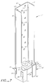
- Figures 1 and 2 show a typical use of the preferred embodiment.
- the first building structural member 2 is a vertical stud of a framed wall and the second building structural member 3 is a concrete foundation.
- the present invention may also be used to transfer tension loads between floors of a framed structure, or to tie joists to masonry or concrete walls, to name but a few applications.
- FIG. 1 Installation of the connector 1 of the preferred embodiment to form a foundation-to-wooden-stud connection is illustrated by figures 1 and 2 .
- an anchor bolt 33 having a threaded top portion is embedded in the second building structural member 3. This can be done by placing the bottom portion of the anchor bolt 33 in the wet concrete or by forming the second building structural member 3 with the top portion of the anchor bolt 33 protruding from it.
- An opening is then drilled in the transfer member 35 and the anchor bolt 33 is inserted therethrough with the threaded portion of the anchor bolt 33 exposed above the top of the transfer member 35.
- the threaded portion of the anchor bolt 33 is inserted between the first and second anchor receiving members 9 and 10, such that it protrudes above the first and second anchor receiving members 9 and 10.
- a washer member 16 having an opening 17 is inserted over the top portion of the anchor bolt 33 so that it rests on the aligned support faces 14 and 15 of the first and second anchor receiving member 9 and 10.
- the back member 6 of the connector 1 is set against the side of the first building structural member 2. Fasteners 4 are driven into the first building structural member 2 through the openings 18 and 19 in the back member 6, forming a tight fit between the back member 6 of the connector 1 and the first building structural member 2.
- a holding member 34 is then placed on the threaded portion of the anchor bolt 33 and tightened down so that it bears upon the washer member 16 and the washer member bears upon the aligned support faces 14 and 15 of the first and second anchor receiving members 9 and 10, completing the anchor member 4, and the connection.
- shearwalls were constructed and anchored with connectors built according to the present invention and compared to shearwalls anchored with a currently-available holdown sold by Simpson Strong-Tie Co. called the PHD8.
- the PHD8 is the subject of U.S. Patent Application Serial No. 08/729,056 , and is described therein.
- the shearwalls were similar in appearance to the wall shown in figure 1 , except that they sat on and were connected to the base of a test frame rather than a foundation.
- the shearwalls consisted of a 4' ⁇ 8' structural panel supported on its long edges by first and second chords and on its short edges by top and bottom struts. Intermediate studs were also spaced between the first and second chords to further strengthen the shearwall.
- shearwalls were tested in Brea, California at the Simpson Strong-Tie Co. Laboratory on a machine designed to simulate the cyclic (reversing) lateral forces that would be imposed on a shearwall or vertical lateral-force-resisting system during an earthquake.
- the test can be used to measure the strength of the shearwall and the stiffness of the shearwall. Stiffness of a shearwall is measured in terms of the force that is required to displace the top of the wall a given distance. The strength of a shearwall can be described in these same terms as well as by how much force is required to cause a failure of the shearwall, that is the point when the shearwall no longer provides any meaningful resistance to lateral forces.
- Test results are reported in table 1 for two different shearwalls in terms of the force required to displace the top of the wall 0.5" under cyclic loading conditions (Load at 0.5"), the force required to displace the top of the wall 1.0" (Load at 1.0"), and the load at which failure of the wall occurs (Maximum Load).
- the test show that a shearwall anchored with holdowns of the present invention performs better than a shearwall anchored by the PHD8.
- the TCCMAR procedure hinges on the concept of the First Major Event (FME), which is defined as the first significant limit state which occurs during the test.
- FME occurs when the load capacity of the wall, upon recycling of load to the same wall displacement increment, first drops noticeably from the original load and displacement. FME for all tests was assumed to occur when an 8 foot high shearwall can be displaced 0.8 inches at its top.
- the TCCMAR procedure consists of applying cycles of fully-reversing displacement to the shearwall at various increments of the wall's assumed FME. The wall is both pushed and pulled an equal distance in each cycle.
- one phase-maximum cycle of fully-reversing displacement is applied at 125% of FME.
- "decay" cycles of displacement for one cycle each at 75%, 50%, and 25% of the maximum for that phase are applied in that order respectively.
- three stabilizing cycles of displacement equal to the phase-maximum for the phase (125% of FME for the second phase) are applied to the shearwall.
- one phase-maximum cycle of fully-reversing displacement at 150% of FME is applied to the shearwall.
- "decay" cycles of displacement for one cycle each at 75%, 50% and 25% of the phase-maximum for the phase are applied.
- three stabilizing cycles of displacement equal to the phase-maximum (150% of FME for the third phase) are applied to the top of the shearwall.
- Successive phases are continued in a like manner as the second and third phases at increased increments.
- the incremental cyclic load-displacement phases are continued at phase-maximums of 175%, 200%, 250%, 300%, 350% and 400% of FME, or until the wall exhibits excessive displacement, or until the wall displacement exceeds the capacity of the test equipment, which in this case was ⁇ 3.0 inches.
- the lateral load capacity of the shearwall had greatly diminished by the time the shearwall was displaced 3.0 inches.
- Racking shear loads were applied to the test specimens through an actuator located at the top of the wall.
- the actuator was placed so that the actuator did not interfere with any movement of the structural panel that formed the webbing of the shearwall.
- the actuator that caused deflection at the top of the shearwall was computer controlled. Actuator loads were applied to the wall at a frequency of one cycle per second.
- the shearwalls were attached to the base of the test frame with 5/8" diameter foundation bolts, passing through the bottom strut, spaced approximately 12" on center, and 12" from the ends of the shearwall.
- Test F945 used the holdown of the present invention.
- Test F910 used the PHD8 holdown.
- the anchor members were 7/8" inch anchor bolts that passed through the bottom strut fitted with a nut.
- the PHD8 holdown and the holdown of the present invention were both attached to the first and second chords of the shearwalls by means of 24 1 ⁇ 4 " x 3" Simpson Strong Drive Screws.
- lumber moisture content for the components of the shearwall at the time of the tests was approximately 20 to 25%.
- top struts were doubled 2 x 4s connected with nails.
- the top struts for each shear wall were 48" long.
- two intermediate 2 x 4 studs, spaced 16" on center from each other and the first and second chords, were added and end-nailed to the top and bottom struts with nails according to currently accepted building practices.
- the first and second chords were approximately 93" tall. This means the chords sat directly on the test frame. Setting the chords on the test frame eliminates failure of the shearwall due to crushing of the bottom strut by the chords, and greatly improves the performance of the shearwall. This particular design of using long chords that bypass the bottom strut is especially effective where the shearwall sits on the relatively non-compressible building foundation.
- the first and second chords were made from individual wood members glued together to form a laminate.
- Oriented Strand Board structural panels were used for the structural panel or shear-resisting element in the tests. Both tests were conducted with one 4' x 8' structural panel applied to the framing members with the face grain or strength axis disposed vertically.
- the structural panels were fastened to the top and bottom struts and the first and second chords by steel 10d common nails that were 3" long. All nails were driven into the framing members to a depth of at least times their shank diameter to comply with the Uniform Building Code. All nails were driven so that the head of the nail sat flush against boundary edging members attached to the structural panel. The nails were generally spaced 2" on center around the periphery of the structural panel. The structural panel was also attached to the intermediate studs with 10d x 3" long common nails. Both tests used "u" shaped boundary edging members to strengthen the connection between the framing members and the structural panel.
Landscapes
- Engineering & Computer Science (AREA)
- Architecture (AREA)
- Physics & Mathematics (AREA)
- Electromagnetism (AREA)
- Civil Engineering (AREA)
- Structural Engineering (AREA)
- Joining Of Building Structures In Genera (AREA)
- Foundations (AREA)
- Buildings Adapted To Withstand Abnormal External Influences (AREA)
Applications Claiming Priority (2)
| Application Number | Priority Date | Filing Date | Title |
|---|---|---|---|
| US09/005,307 US6006487A (en) | 1998-01-09 | 1998-01-09 | Loadbearing wall holdown |
| US5307 | 1998-01-09 |
Related Child Applications (1)
| Application Number | Title | Priority Date | Filing Date |
|---|---|---|---|
| EP10185951.0 Division-Into | 2010-10-01 |
Publications (3)
| Publication Number | Publication Date |
|---|---|
| EP0928852A2 EP0928852A2 (en) | 1999-07-14 |
| EP0928852A3 EP0928852A3 (en) | 2000-04-05 |
| EP0928852B1 true EP0928852B1 (en) | 2012-02-22 |
Family
ID=21715224
Family Applications (1)
| Application Number | Title | Priority Date | Filing Date |
|---|---|---|---|
| EP98309425A Expired - Lifetime EP0928852B1 (en) | 1998-01-09 | 1998-11-18 | Holdown |
Country Status (6)
| Country | Link |
|---|---|
| US (2) | US6006487A (enExample) |
| EP (1) | EP0928852B1 (enExample) |
| JP (1) | JP4118431B2 (enExample) |
| AU (1) | AU741454B2 (enExample) |
| CA (1) | CA2252652C (enExample) |
| NZ (1) | NZ332728A (enExample) |
Families Citing this family (57)
| Publication number | Priority date | Publication date | Assignee | Title |
|---|---|---|---|---|
| US5706626A (en) | 1995-12-14 | 1998-01-13 | Mueller; Lee W. | Pre-assembled internal shear panel |
| US7251920B2 (en) * | 1997-04-14 | 2007-08-07 | Timmerman Sr Timothy L | Lateral force resisting system |
| US8397454B2 (en) | 1997-11-21 | 2013-03-19 | Simpson Strong-Tie Company, Inc. | Building wall for resisting lateral forces |
| US6550200B1 (en) * | 1999-06-16 | 2003-04-22 | Lee W. Mueller | Anchor interconnect device |
| US6389767B1 (en) | 2000-01-06 | 2002-05-21 | Zone Four, Llc | Shear wall construction |
| US7150132B2 (en) * | 2003-08-12 | 2006-12-19 | Commins Alfred D | Continuous hold-down system |
| USD467007S1 (en) | 2000-05-18 | 2002-12-10 | Dietrich Industries, Inc. | Building component support header |
| US6430881B1 (en) | 2000-05-18 | 2002-08-13 | Aegis Metal Framing Llc | Top plate |
| US20070062135A1 (en) * | 2000-06-30 | 2007-03-22 | Mueller Lee W | Corrugated shear panel and anchor interconnect system |
| US6625945B2 (en) * | 2000-08-08 | 2003-09-30 | Alfred D. Commins | Balanced, multi-stud hold-down |
| US6560940B2 (en) | 2000-08-18 | 2003-05-13 | Lee W. Mueller | Two-piece clinched plate tension/compression bracket |
| US6761001B2 (en) * | 2000-08-18 | 2004-07-13 | Lee W. Mueller | Frame shear assembly for walls |
| US6453634B1 (en) * | 2000-12-01 | 2002-09-24 | Simpson Strong-Tie Company, Inc. | Moment-resisting strap connection |
| US7509778B2 (en) * | 2000-12-03 | 2009-03-31 | Simpson Strong-Tie Company, Inc. | Automatic take-up device with internal spring |
| US6460308B1 (en) | 2001-02-05 | 2002-10-08 | John Armstrong | Foundation bolt rework kit and method of using same |
| US6668508B2 (en) | 2001-08-28 | 2003-12-30 | Weyerhaeuser Company | Shear panel assembly |
| US20030136075A1 (en) * | 2002-01-18 | 2003-07-24 | Brackett Charles T | Construction brace for use against seismic and high wind conditions |
| US8082703B2 (en) * | 2002-02-11 | 2011-12-27 | Ei-Land Corporation | Force-resisting devices and methods for structures |
| US7043879B2 (en) * | 2002-02-11 | 2006-05-16 | Ei-Land Corporation | Force-resisting devices and methods for structures |
| US8387321B2 (en) * | 2002-03-12 | 2013-03-05 | The Steel Network, Inc. | Connector for connecting building components |
| US8127502B2 (en) | 2002-08-06 | 2012-03-06 | EI-Land Corp. | Building structure configured to exhibit a prescribed load-deflection relationship when a force is applied thereto |
| US20040040236A1 (en) * | 2002-08-27 | 2004-03-04 | James Adams | Dual function connector |
| US6941712B2 (en) * | 2002-10-01 | 2005-09-13 | Sukup Manufacturing Company | Mounting bracket for grain bin |
| US7131238B2 (en) * | 2003-07-21 | 2006-11-07 | Fm Global Technologies, Llc | Method of testing seismic braces |
| US7162843B2 (en) * | 2003-08-14 | 2007-01-16 | Mitek Holdings, Inc. | Bolts with connected anchor |
| US7117648B1 (en) | 2003-10-21 | 2006-10-10 | John Duncan Pryor | Cross tie connection bracket |
| US7958690B2 (en) * | 2003-10-24 | 2011-06-14 | Simpson Strong-Tie Co., Inc. | Stitching system hold-down |
| US20050086895A1 (en) * | 2003-10-27 | 2005-04-28 | Elliot A. C. | Compression post for structural shear wall |
| US7506479B2 (en) * | 2004-08-17 | 2009-03-24 | Simpson Strong-Tie Company, Inc. | Shear transfer plate |
| US7168343B2 (en) | 2005-03-09 | 2007-01-30 | Simpson Strong-Tie Company, Inc. | Limited access building connection |
| US7520102B1 (en) * | 2005-08-26 | 2009-04-21 | The Steel Network, Inc. | Anchor bolt assembly having a corrosion resistant bushing |
| US20070107338A1 (en) * | 2005-10-27 | 2007-05-17 | Dietrich Industries, Inc. | Hold-down connector |
| US20070113516A1 (en) * | 2005-10-27 | 2007-05-24 | Dietrich Industries, Inc. | Hold-down connectors and wall systems |
| US7856763B2 (en) * | 2006-03-07 | 2010-12-28 | Mitek Holdings, Inc. | Truss hold-down connectors and methods for attaching a truss to a bearing member |
| US20070209311A1 (en) * | 2006-03-07 | 2007-09-13 | Aegis Metal Framing Llc | Truss hold-down connectors and methods for attaching a truss to a bearing member |
| US20070245677A1 (en) * | 2006-03-31 | 2007-10-25 | Hien Nguyen | Column holdown connection |
| US8234826B1 (en) * | 2006-06-15 | 2012-08-07 | Proffitt Jr Ray A | Hold down clip |
| US20080115426A1 (en) * | 2006-11-16 | 2008-05-22 | John Paul Hawkins | Roof load transfer system |
| US8689518B2 (en) * | 2007-03-06 | 2014-04-08 | Bay City Flower Company, Inc. | Continuity tie for prefabricated shearwalls |
| US7905066B2 (en) | 2007-04-06 | 2011-03-15 | Simpson Strong-Tie Co., Inc. | Automatic take-up device and in-line coupler |
| US8910439B2 (en) | 2007-04-11 | 2014-12-16 | M3house, LLC | Wall panels for affordable, sustainable buildings |
| US7941975B2 (en) * | 2007-04-11 | 2011-05-17 | Erla Dogg Ingjaldsdottir | Affordable, sustainable buildings comprised of recyclable materials and methods thereof |
| US8429871B2 (en) * | 2007-04-11 | 2013-04-30 | Erla Dögg Ingjaldsdottir | Affordable, sustainable buildings comprised of recyclable materials and methods thereof |
| US20080265128A1 (en) * | 2007-04-26 | 2008-10-30 | Craig Morrow Hughes | Stabilizing apparatus for securing anchor bolts |
| US7712282B2 (en) * | 2007-09-27 | 2010-05-11 | Weyerhaeuser Nr Company | Brace assembly having ductile anchor |
| US9097000B2 (en) | 2008-10-03 | 2015-08-04 | Thomas M. Espinosa | Hold down system using hollow bearing members |
| US8555580B2 (en) | 2008-12-30 | 2013-10-15 | Simpson Strong-Tie Co., Inc. | Multipurpose holdown |
| US8302357B1 (en) * | 2010-10-26 | 2012-11-06 | Kontek Industries, Inc. | Blast-resistant foundations |
| JP5995466B2 (ja) * | 2012-03-12 | 2016-09-21 | 住友林業株式会社 | 木造建築構造躯体 |
| US8881478B2 (en) | 2012-06-22 | 2014-11-11 | Simpson Strong-Tie Company, Inc. | Ratcheting take-up device |
| JP6202931B2 (ja) * | 2013-08-06 | 2017-09-27 | 住友林業株式会社 | 結合部材、結合部材の製造方法及び木部材接合構造 |
| US9394706B2 (en) | 2013-10-08 | 2016-07-19 | Simpson Strong-Tie Company, Inc. | Concrete anchor |
| US9163655B2 (en) | 2014-01-14 | 2015-10-20 | Kaoru Taneichi | Thrust nut |
| US11155977B2 (en) * | 2017-04-27 | 2021-10-26 | Simpson Strong-Tie Company, Inc. | Portal frame with lap joint for moment resistance |
| WO2019173714A1 (en) | 2018-03-09 | 2019-09-12 | Cetres Holdings, Llc | Reinforced stud-framed wall |
| US20250092663A1 (en) * | 2023-09-20 | 2025-03-20 | Simpson Strong-Tie Company Inc. | Preassembled holdown post |
| US20250223796A1 (en) * | 2024-01-09 | 2025-07-10 | Simpson Strong-Tie Company Inc. | Corrugated shearwall |
Family Cites Families (18)
| Publication number | Priority date | Publication date | Assignee | Title |
|---|---|---|---|---|
| US414169A (en) * | 1889-10-29 | William reuschel | ||
| US1806607A (en) * | 1931-05-26 | brown | ||
| US1704593A (en) * | 1927-07-25 | 1929-03-05 | Omer L Downing | Concrete insert |
| US2169474A (en) * | 1938-03-18 | 1939-08-15 | Myron K Pederson | Building frame construction |
| US2321221A (en) * | 1940-11-18 | 1943-06-08 | Irvin D Linehan | Joist anchoring bracket |
| US4192118A (en) * | 1978-12-13 | 1980-03-11 | Simpson Manufacturing Co., Inc. | Holdown for attaching wood framing members to concrete foundations |
| US4348002A (en) * | 1980-03-25 | 1982-09-07 | Eyden Everett A | Hanger for concrete deck forming apparatus |
| US4321776A (en) * | 1980-09-22 | 1982-03-30 | Art Delight Construction | Shear wall anchoring |
| US4665672A (en) * | 1985-03-20 | 1987-05-19 | Simpson Strong-Tie Company, Inc. | One piece, non-welded holdown |
| US4744192A (en) * | 1987-05-11 | 1988-05-17 | Simpson Strong-Tie Company, Inc. | Tension tie |
| US4825621A (en) * | 1987-12-10 | 1989-05-02 | Mitek Industries, Inc. | Holddown |
| US5092097A (en) * | 1990-09-10 | 1992-03-03 | United Steel Products Co. | Holddown connector |
| US5249404A (en) * | 1992-05-11 | 1993-10-05 | Simpson Strong-Tie Company, Inc. | Holdown connection |
| US5375384A (en) * | 1993-01-22 | 1994-12-27 | Wolfson; Yehuda | Holdown apparatus for a shear wall |
| US5364214A (en) * | 1993-04-28 | 1994-11-15 | Scott Fazekas | Self adjusting construction tie-down |
| US5467570A (en) * | 1994-10-12 | 1995-11-21 | Simpson Strong-Tie Co., Inc. | Tension tie |
| US5813181A (en) * | 1995-08-21 | 1998-09-29 | Ashton; Roger Wall | Continuity tie |
| US5979130A (en) * | 1996-10-10 | 1999-11-09 | Simpson Strong-Tie Company, Inc. | Connector with concave seat |
-
1998
- 1998-01-09 US US09/005,307 patent/US6006487A/en not_active Expired - Lifetime
- 1998-11-03 CA CA002252652A patent/CA2252652C/en not_active Expired - Lifetime
- 1998-11-11 NZ NZ332728A patent/NZ332728A/xx not_active IP Right Cessation
- 1998-11-18 EP EP98309425A patent/EP0928852B1/en not_active Expired - Lifetime
-
1999
- 1999-01-08 AU AU10086/99A patent/AU741454B2/en not_active Expired
- 1999-01-11 JP JP00411899A patent/JP4118431B2/ja not_active Expired - Lifetime
- 1999-11-23 US US09/448,094 patent/US6327831B1/en not_active Expired - Lifetime
Also Published As
| Publication number | Publication date |
|---|---|
| AU741454B2 (en) | 2001-11-29 |
| CA2252652A1 (en) | 1999-07-09 |
| AU1008699A (en) | 1999-09-16 |
| JPH11256700A (ja) | 1999-09-21 |
| CA2252652C (en) | 2007-10-23 |
| NZ332728A (en) | 2000-03-27 |
| US6327831B1 (en) | 2001-12-11 |
| EP0928852A2 (en) | 1999-07-14 |
| US6006487A (en) | 1999-12-28 |
| JP4118431B2 (ja) | 2008-07-16 |
| EP0928852A3 (en) | 2000-04-05 |
Similar Documents
| Publication | Publication Date | Title |
|---|---|---|
| EP0928852B1 (en) | Holdown | |
| CA2238876C (en) | Diaphragm with perimeter edging on structural panels | |
| US8397454B2 (en) | Building wall for resisting lateral forces | |
| EP1337720B1 (en) | Connector | |
| US6550200B1 (en) | Anchor interconnect device | |
| US5249404A (en) | Holdown connection | |
| CA2240569C (en) | Holdown connector with concave seat | |
| JPH11222960A5 (enExample) | ||
| CA2214944C (en) | Connector with concave seat | |
| CA1325874C (en) | Structural connection system | |
| US8555580B2 (en) | Multipurpose holdown | |
| CA2593387C (en) | Holdown | |
| JP3069945U (ja) | 木造建築物の耐震補強金物及び耐震補強構造 | |
| AU706721B2 (en) | Building frame fastening arrangement | |
| CA2144798A1 (en) | Anti-racking device for wood framed and other buildings | |
| Talbot et al. | Structural performance of stapled wood shear walls under dynamic cyclic loads | |
| NZ501392A (en) | Diaphragm with perimeter edging on structural panels which resists lateral forces |
Legal Events
| Date | Code | Title | Description |
|---|---|---|---|
| PUAI | Public reference made under article 153(3) epc to a published international application that has entered the european phase |
Free format text: ORIGINAL CODE: 0009012 |
|
| AK | Designated contracting states |
Kind code of ref document: A2 Designated state(s): DE FR GB |
|
| AX | Request for extension of the european patent |
Free format text: AL;LT;LV;MK;RO;SI |
|
| PUAL | Search report despatched |
Free format text: ORIGINAL CODE: 0009013 |
|
| AK | Designated contracting states |
Kind code of ref document: A3 Designated state(s): AT BE CH CY DE DK ES FI FR GB GR IE IT LI LU MC NL PT SE |
|
| AX | Request for extension of the european patent |
Free format text: AL;LT;LV;MK;RO;SI |
|
| 17P | Request for examination filed |
Effective date: 20001005 |
|
| AKX | Designation fees paid |
Free format text: DE FR GB |
|
| 17Q | First examination report despatched |
Effective date: 20030811 |
|
| GRAP | Despatch of communication of intention to grant a patent |
Free format text: ORIGINAL CODE: EPIDOSNIGR1 |
|
| GRAS | Grant fee paid |
Free format text: ORIGINAL CODE: EPIDOSNIGR3 |
|
| GRAA | (expected) grant |
Free format text: ORIGINAL CODE: 0009210 |
|
| RAP1 | Party data changed (applicant data changed or rights of an application transferred) |
Owner name: SIMPSON STRONG-TIE COMPANY, INC. |
|
| AK | Designated contracting states |
Kind code of ref document: B1 Designated state(s): DE FR GB |
|
| REG | Reference to a national code |
Ref country code: GB Ref legal event code: FG4D |
|
| REG | Reference to a national code |
Ref country code: DE Ref legal event code: R096 Ref document number: 69842602 Country of ref document: DE Effective date: 20120419 |
|
| PLBE | No opposition filed within time limit |
Free format text: ORIGINAL CODE: 0009261 |
|
| STAA | Information on the status of an ep patent application or granted ep patent |
Free format text: STATUS: NO OPPOSITION FILED WITHIN TIME LIMIT |
|
| 26N | No opposition filed |
Effective date: 20121123 |
|
| REG | Reference to a national code |
Ref country code: DE Ref legal event code: R097 Ref document number: 69842602 Country of ref document: DE Effective date: 20121123 |
|
| REG | Reference to a national code |
Ref country code: FR Ref legal event code: PLFP Year of fee payment: 18 |
|
| REG | Reference to a national code |
Ref country code: FR Ref legal event code: PLFP Year of fee payment: 19 |
|
| REG | Reference to a national code |
Ref country code: FR Ref legal event code: PLFP Year of fee payment: 20 |
|
| PGFP | Annual fee paid to national office [announced via postgrant information from national office to epo] |
Ref country code: DE Payment date: 20171117 Year of fee payment: 20 Ref country code: FR Payment date: 20171115 Year of fee payment: 20 |
|
| PGFP | Annual fee paid to national office [announced via postgrant information from national office to epo] |
Ref country code: GB Payment date: 20171124 Year of fee payment: 20 |
|
| REG | Reference to a national code |
Ref country code: DE Ref legal event code: R071 Ref document number: 69842602 Country of ref document: DE |
|
| REG | Reference to a national code |
Ref country code: GB Ref legal event code: PE20 Expiry date: 20181117 |
|
| PG25 | Lapsed in a contracting state [announced via postgrant information from national office to epo] |
Ref country code: GB Free format text: LAPSE BECAUSE OF EXPIRATION OF PROTECTION Effective date: 20181117 |