EP0928761B1 - Process and apparatus for transport of panels made of mineral wool or other insulation material - Google Patents
Process and apparatus for transport of panels made of mineral wool or other insulation material Download PDFInfo
- Publication number
- EP0928761B1 EP0928761B1 EP99300245A EP99300245A EP0928761B1 EP 0928761 B1 EP0928761 B1 EP 0928761B1 EP 99300245 A EP99300245 A EP 99300245A EP 99300245 A EP99300245 A EP 99300245A EP 0928761 B1 EP0928761 B1 EP 0928761B1
- Authority
- EP
- European Patent Office
- Prior art keywords
- pallet
- control
- panels
- column
- tilted
- Prior art date
- Legal status (The legal status is an assumption and is not a legal conclusion. Google has not performed a legal analysis and makes no representation as to the accuracy of the status listed.)
- Expired - Lifetime
Links
- 238000000034 method Methods 0.000 title claims description 11
- 239000011490 mineral wool Substances 0.000 title claims description 10
- 239000012774 insulation material Substances 0.000 title claims description 6
- 238000004519 manufacturing process Methods 0.000 claims description 50
- 230000033001 locomotion Effects 0.000 claims description 19
- 230000007246 mechanism Effects 0.000 claims description 6
- 230000001276 controlling effect Effects 0.000 claims description 5
- 230000001105 regulatory effect Effects 0.000 claims description 3
- 230000003028 elevating effect Effects 0.000 claims 1
- 238000012544 monitoring process Methods 0.000 claims 1
- 230000032258 transport Effects 0.000 description 19
- 239000000835 fiber Substances 0.000 description 2
- 230000001360 synchronised effect Effects 0.000 description 2
- 238000006073 displacement reaction Methods 0.000 description 1
- 239000011491 glass wool Substances 0.000 description 1
- 238000009413 insulation Methods 0.000 description 1
- 239000000463 material Substances 0.000 description 1
- 238000005457 optimization Methods 0.000 description 1
- 239000002245 particle Substances 0.000 description 1
- 230000002265 prevention Effects 0.000 description 1
- 230000000750 progressive effect Effects 0.000 description 1
- 238000003860 storage Methods 0.000 description 1
- 239000000126 substance Substances 0.000 description 1
- 230000007723 transport mechanism Effects 0.000 description 1
Images

Classifications
-
- B—PERFORMING OPERATIONS; TRANSPORTING
- B65—CONVEYING; PACKING; STORING; HANDLING THIN OR FILAMENTARY MATERIAL
- B65H—HANDLING THIN OR FILAMENTARY MATERIAL, e.g. SHEETS, WEBS, CABLES
- B65H1/00—Supports or magazines for piles from which articles are to be separated
- B65H1/30—Supports or magazines for piles from which articles are to be separated with means for replenishing the pile during continuous separation of articles therefrom
-
- B—PERFORMING OPERATIONS; TRANSPORTING
- B65—CONVEYING; PACKING; STORING; HANDLING THIN OR FILAMENTARY MATERIAL
- B65H—HANDLING THIN OR FILAMENTARY MATERIAL, e.g. SHEETS, WEBS, CABLES
- B65H15/00—Overturning articles
- B65H15/02—Overturning piles
-
- B—PERFORMING OPERATIONS; TRANSPORTING
- B65—CONVEYING; PACKING; STORING; HANDLING THIN OR FILAMENTARY MATERIAL
- B65H—HANDLING THIN OR FILAMENTARY MATERIAL, e.g. SHEETS, WEBS, CABLES
- B65H15/00—Overturning articles
- B65H15/008—Overturning articles employing belts
Definitions
- This invention relates to a process and apparatus for transport of panels made of mineral wool or other insulation material on to a production line or assembly line for further manufacturing.
- the technical problem which is addressed by the present invention is the optimization of the transport of panels made of mineral wool or other insulation material in panel or plate or slab form on to a production (assembly) line on which said panels are further used. Said technical problem can be further broken down into sub-problems, as follows:
- Transport apparata are well known, however not transport mechanisms for the transport of mineral wool in form of the mineral wool panels whereby said panels are stacked on to pallets, and said panels should be put on to conveyer belts by yanking (pulling) an individual panel from the stack of said panels.
- European Patent Application No EP 0742166 A2 shows an apparatus where a set of palletized items, held in layers on a standard pallet, each layer comprising a plurality of parallel rows, can be off loaded by the progressive sideways urging by a pusher, parallel row followed by parallel row, from each successive layer onto an angled linear transporter. With each successive layer having been unloaded, the pusher and the angled transporter drop to the next layer. The items are transported away from the pallet, in a single row, by the angled transporter.
- EP 0742166 is silent upon means whereby items may be removed from the angled transporter and placed upon a conveyor.
- the present invention seeks to provide a means whereby, at least fibre panels, may be removed from an angled transporter and placed, in a controlled fashion, upon a linear transporter.
- Standardized pallets (hereinafter 'pallets') should be used for transport and stocking.
- the process and apparatus according to invention perform their function is such a way that a transporter (1) performing a function of transporting is loaded by means of a fork lift performing a function of loading.
- the load comprises a pallet with stacked mineral wool panels or panels of other insulation material (hereinafter 'panels').
- the transporter (1) can be of chain, belt or some other type and can carry one or more pallets.
- the content of a particular pallet can provide an assembly line with an appropriate number of panels depending on the assembly line speed.
- the transporter (1) should be equipped with several control apparata for controlling parameters such as the final position of the pallet, the removal of pallets, the next free position, engagement. Engagement in this patent application is a general term meaning that a particular position is not free, but engaged (full).
- a reloader (2) performs the function of transporting the pallets from the transporter (1) to a roller transporter (3). It can be of chain, belt or any other type. Reloader (2) takes over a particular pallet from the transporter (1) after a previous pallet has been reloaded. Reloader (2) can feature similar control sensors as the transporter (1). After taking the pallet from the transporter (1) the reloader (2) positions itself at the level of roller transporter (3) and reloads the pallet on to said roller transporter (3). After this task has been accomplished, it returns again to the level of transporter (1) to repeat the procedure.
- the roller transporter (3) which co-performs the function of transporting the pallet or a plurality thereof then transports the pallet to a cross pusher (4) which empties the pallet. Said empty pallet is then transported by the roller transporter (3) to a palletizer (8) which stacks empty pallets to be ready for removal (transport).
- Said roller transporter (3) can be equipped with control sensors, e.g. at the location of the cross pusher (4) to control parameters such as: position of the pallet, removal of the pallet, engagement, and control of next free position. It can be also equipped with control sensors at the location of the palletizer (8) for controlling parameters such as: final position of pallet, removal (transport) of pallets, and engagement.
- the transporter (1), the reloader (2), the roller transporter (3), and the palletizer (8) perform the function of transport.
- the cross pusher (4) which performs the function of pushing a stack or column (9) of panels from the pallet onto a pivoting reloader (5) to be described hereunder has one or several positions from which it performs its function, so-called pushing positions.
- the number of these pushing positions corresponds to the number of panel columns (9) on a particular pallet.
- the number of panels stacked in a particular panel column (9) is limited only by the mechanical characteristics of the particular panels; however, in the preferred embodiment between 25 and 35 panels are foreseen.
- the cross pusher (4) performs its function by pushing the panel column (9) from its position on the roller transporter (3) on to the pivoting reloader (5).
- Said pivoting reloader (5) changes the orientation of said panel column (9) from upright to slanted whereby the slanted position is described by an angle a formed by collinear normals of planes (surfaces) of said panels stacked into said panel column (9) and the vertical.
- Said angle ⁇ is arbitrary, however it should be approximately equal to an angle formed by a vertical line and the direction of a tilted transporter (6) movement.
- the pivoting reloader (5) reloads the panel column (9) by a pivoting movement on to the tilted transporter (6). Said reloading action can be performed at any time, however, the optimum is achieved when there is enough room for a whole panel column (9) on the tilted transporter (6).
- the tilted transporter (6) facilitates the movement of the panel column (9) by means of forks which push the panel column (9) along the tilted transporter's (6) surface toward a production line conveyer (7).
- the pivoting reloader (5) returns to the original position and awaits the next panel column (9).
- the cross pusher (4) in the preferred embodiment pushes exactly one panel column (9) on to the pivoting reloader (9) each time the pivoting reloader (5) completes its movement.
- said roller transporter (3) in a preferred embodiment moves the pallet essentially for the width of said panel column (9) so the cross pusher (4) and pivoting reloader (5) perform their function and dispose of all panel columns (9) populating the pallet on to the tilted transporter (6) and then onto production line conveyer (7).
- the pivoting reloader (5) can be additionally equipped with at least one side guide/railing/holder of panel column (9), said device being used to ensure that the panel column does not shift uncontrollably.
- the cross pusher (4) can be equipped with control sensors for control of the steps of the cross pusher (4), the position of the pallet depending on the length of the panels, and engagement.
- the pivoting reloader (5) can be equipped with sensors for control of its position, control of next free position, and control of the side guide/railing/holder of panel column (9).
- the tilted transporter (6) can be for example equipped with sensors for control of: position of forks, next free position, final position of each panel, and control counter of panel exit.
- the velocity of movement of panel column (9) on the tilted transporter (6) can be synchronized with production line conveyer (7) which takes over individual panels from the tilted transporter (6) and delivers individual panels to the production or assembly line for further manufacturing.
- said current top panel (10) lower edge is yanked in the direction of said moving surface motion thereby causing said top panel (10) to lie with its base surface on the conveyer belt of the production line conveyer (7) which transports said panel to the production or assembly line thereby achieving the objective.
- the present invention achieves transport of individual panels despite possible attachment between surface fibers of two adjacent surfaces of two adjacent panels in the panel column (9).
- the velocity of the movement ofthe forks of said tilted transporter (6) and the velocity of the movement of the production line conveyer (7) should be adjusted to achieve a proper distance between individual panels when transported on said production line conveyer (7). Too fast a movement of the forks of tilted transporter (6) when compared to the speed of movement of the production line conveyer (7) causes too rapid a succession of individual panels on the surface of the production line conveyer (7) and probable collision between adjacent panels or double panels instead of individual ones.
- the cross pusher (4), pivoting reloader (5), and tilted transporter (6) perform the function of sorting, as described above.
- the production line conveyer (7) which can be also called an exit conveyer if used for other means than for feeding the production or assembly line in a process of further manufacturing the panels, can have a belt as the transport or moving surface.
- the surface of the belt may be profiled in order to achieve better results at gripping and pulling on the lower edge of current top panel (10) as well as better holding of said panel when transported to its final destination (usually a production or assembly line).
- the driving mechanisms or engines of both tilted transporter (6) and/or production line conveyer (7) can be regulated by frequency to achieve appropriate velocities depending on the demands of the production or assembly line, said regulation being achieved by means of a micro processor.
- the production line conveyer (7) can be for example equipped with sensors for control of the next free position and control of engagement.
- the production line conveyer performs the function of exit from the apparatus of the invention.
- Palletizer (8) stacks empty pallets into a column until said column reaches the desired height, in a preferred embodiment 6 pallets. As soon as the desired height is achieved, a fork lift or other type of transporting device can remove or transport the pallets, thereby emptying the palletizer (8) and enabling successive pallets to be stacked.
- Palletizer (8) can be equipped with side guides/railings/holders for the pallet column, said device being used to ensure that the pallet column does not shift uncontrollably and can be for example equipped with control sensors for the lifting mechanism and the distance between side guides/railings/holders.
- the above described transporter system can be equipped with a control panel, said panel being suitably equipped for controlling said system, particularly automated entry of the individual panels on to the production/assembly line.
- a control center enabling centralized control and regulation of the system depending on the automated entry of the individual panels on to the production/assembly line.
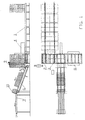
- Fig. 1 shows the subject of this invention with the transporter (1), the reloader (2), the roller transporter (3), the cross pusher of panel column (4), the pivoting reloader (5), the tilted transporter (6), the production line conveyer (7), the palletizer (8), the panel column (9), and the current top panel (10).
- Fig. 2. shows a standardized pallet with its characteristics for transport of the panel columns (9).
- the subject of the invention is used for a system of automated feeding of panels made of mineral wool into a production or assembly line for manufacturing light building panels made of mineral wool.
- the transporter (1) is of the chain type and is equipped with safety edge for fork lift.
- the capacity of said transporter (1) is 3 to 7 pallets which ensures a continuous supply to the production or assembly line for light building panels manufacturing.
- the reloader (2) is of the chain type and takes over the pallet from the transporter (1) as soon as it is vacated by the previous pallet. After taking over the pallet, the reloader (2) changes its level to that of the roller transporter (3) and reloads the pallet on to the roller transporter (3).
- the roller transporter (3) transports the pallet to the cross pusher (4) of panel columns (9) which empties (successfully) the pallet. Said empty pallet is then transported by said roller transporter (3) to the palletizer (8), said palletizer being equipped with side holders.
- Said cross pusher (4) pushes the panel column (9) on to the pivoting reloader (5).
- Said pivoting reloader (5) then reloads the panel column (9) on to the tilted transporter (6) as soon as there is enough space for the whole panel column on the tilted transporter's (6) surface.
- said pivoting reloader(5) returns to the original position and awaits the next panel column (9) to be pushed on to it by the cross pusher(4). Should there be several panel columns on the pallet in the transverse direction the cross pusher pushes one panel column(9) on to the pivoting reloader (5) each time.
- the roller transporter (3) each time moves the pallet essentially for the width of said panel column (9) so the cross pusher (4) and pivoting reloader (5) perform their function and dispose of all panel columns (9) populating the pallet on to the tilted transporter (6) and then on to the production line conveyer (7).
- the number of repetitions of said operation of the cross pusher (4) etc. is determined on the control panel depending on the number of panel columns (9) in the transverse and longitudinal directions.
- the velocity of movement of the panel column (9) on the tilted transporter (6) can be synchronized with the production line conveyer (7) which takes over the panels from the tilted transporter (6) by pulling the lower edge of the current top panel (10) in the direction of surface motion of said moving production line conveyer (7) thereby causing said top panel (10) to lie with its base surface on the conveyer belt of the production line conveyer (7).
- the surface of the belt features an appropriate profile in order to achieve better results at gripping and yanking (pulling) of the lower edge of the current top panel (10).
- the driving mechanisms or engines of both the tilted transporter (6) and/or production line conveyer (7) are regulated by frequency to achieve appropriate velocities depending on the demands of the production or assembly line.
- Palletizer stacks empty pallets into a column in such a fashion that the empty pallets are raised to the height of the side holders, said holders holding the pallet under its edge. Each pallet during the elevation takes over the weight of all previous pallets until the column reaches the desired height. After the desired height has been reached, the pallets are transported using the lift fork or other type of transporting mechanism to an appropriate storage place.
- the whole system is controlled by the control panel which is suitably equipped to control and regulate the described system.
- control points are equipped with standard equipment in form elements such as photo cells or other types of position sensors, these elements being well known to the person skill in the automation and control of transport system art and comprised in the state of said art.
Landscapes
- Engineering & Computer Science (AREA)
- Mechanical Engineering (AREA)
- Attitude Control For Articles On Conveyors (AREA)
- Intermediate Stations On Conveyors (AREA)
Description
- This invention relates to a process and apparatus for transport of panels made of mineral wool or other insulation material on to a production line or assembly line for further manufacturing. Several partial solutions were necessary to address the above described single technical problem. The general field of the invention lies in transporters, and the transport of panels.
- The technical problem which is addressed by the present invention is the optimization of the transport of panels made of mineral wool or other insulation material in panel or plate or slab form on to a production (assembly) line on which said panels are further used. Said technical problem can be further broken down into sub-problems, as follows:
- the continuous loading of panels on to production line for further manufacturing;
- synchronization of the speed of transport of said panels with said production line;
- the individual transport of said panels whereby the displacement ofsaid panel from the desired position should be reduced to a minimum;
- prevention of contact between workers and harmful material (e.g. glass wool particles);
- the automated stacking of pallets (platforms on which the panels were delivered) to a desired height for stocking.
- Transport apparata are well known, however not transport mechanisms for the transport of mineral wool in form of the mineral wool panels whereby said panels are stacked on to pallets, and said panels should be put on to conveyer belts by yanking (pulling) an individual panel from the stack of said panels.
- European Patent Application No EP 0742166 A2 shows an apparatus where a set of palletized items, held in layers on a standard pallet, each layer comprising a plurality of parallel rows, can be off loaded by the progressive sideways urging by a pusher, parallel row followed by parallel row, from each successive layer onto an angled linear transporter. With each successive layer having been unloaded, the pusher and the angled transporter drop to the next layer. The items are transported away from the pallet, in a single row, by the angled transporter. EP 0742166 is silent upon means whereby items may be removed from the angled transporter and placed upon a conveyor. The present invention, among other objectives, seeks to provide a means whereby, at least fibre panels, may be removed from an angled transporter and placed, in a controlled fashion, upon a linear transporter.
- For convenience, the following general description includes reference numerals which match those used in the drawings, which are described in more detail later.
- Standardized pallets (hereinafter 'pallets') should be used for transport and stocking. The process and apparatus according to invention perform their function is such a way that a transporter (1) performing a function of transporting is loaded by means of a fork lift performing a function of loading. The load comprises a pallet with stacked mineral wool panels or panels of other insulation material (hereinafter 'panels'). The transporter (1) can be of chain, belt or some other type and can carry one or more pallets. The content of a particular pallet can provide an assembly line with an appropriate number of panels depending on the assembly line speed. To automate the process the transporter (1) should be equipped with several control apparata for controlling parameters such as the final position of the pallet, the removal of pallets, the next free position, engagement. Engagement in this patent application is a general term meaning that a particular position is not free, but engaged (full).
- A reloader (2) performs the function of transporting the pallets from the transporter (1) to a roller transporter (3). It can be of chain, belt or any other type. Reloader (2) takes over a particular pallet from the transporter (1) after a previous pallet has been reloaded. Reloader (2) can feature similar control sensors as the transporter (1). After taking the pallet from the transporter (1) the reloader (2) positions itself at the level of roller transporter (3) and reloads the pallet on to said roller transporter (3). After this task has been accomplished, it returns again to the level of transporter (1) to repeat the procedure.
- The roller transporter (3) which co-performs the function of transporting the pallet or a plurality thereof then transports the pallet to a cross pusher (4) which empties the pallet. Said empty pallet is then transported by the roller transporter (3) to a palletizer (8) which stacks empty pallets to be ready for removal (transport). Said roller transporter (3) can be equipped with control sensors, e.g. at the location of the cross pusher (4) to control parameters such as: position of the pallet, removal of the pallet, engagement, and control of next free position. It can be also equipped with control sensors at the location of the palletizer (8) for controlling parameters such as: final position of pallet, removal (transport) of pallets, and engagement.
- The transporter (1), the reloader (2), the roller transporter (3), and the palletizer (8) perform the function of transport.
- The cross pusher (4) which performs the function of pushing a stack or column (9) of panels from the pallet onto a pivoting reloader (5) to be described hereunder has one or several positions from which it performs its function, so-called pushing positions. The number of these pushing positions corresponds to the number of panel columns (9) on a particular pallet. The number of panels stacked in a particular panel column (9) is limited only by the mechanical characteristics of the particular panels; however, in the preferred embodiment between 25 and 35 panels are foreseen. The cross pusher (4) performs its function by pushing the panel column (9) from its position on the roller transporter (3) on to the pivoting reloader (5). Said pivoting reloader (5) changes the orientation of said panel column (9) from upright to slanted whereby the slanted position is described by an angle a formed by collinear normals of planes (surfaces) of said panels stacked into said panel column (9) and the vertical. Said angle α is arbitrary, however it should be approximately equal to an angle formed by a vertical line and the direction of a tilted transporter (6) movement. The pivoting reloader (5) reloads the panel column (9) by a pivoting movement on to the tilted transporter (6). Said reloading action can be performed at any time, however, the optimum is achieved when there is enough room for a whole panel column (9) on the tilted transporter (6). The tilted transporter (6) facilitates the movement of the panel column (9) by means of forks which push the panel column (9) along the tilted transporter's (6) surface toward a production line conveyer (7). As soon as the panel column rests on the forks of said tilted transporter (6) the pivoting reloader (5) returns to the original position and awaits the next panel column (9). If there are more panel columns (9) in a transverse direction (i.e. a direction perpendicular to the roller transporter (3) movement) on the same pallet, the cross pusher (4) in the preferred embodiment pushes exactly one panel column (9) on to the pivoting reloader (9) each time the pivoting reloader (5) completes its movement. If there are several panel columns (9) on the same pallet in a longitudinal direction (i.e. a direction parallel with the roller transporter (3) movement), said roller transporter (3) in a preferred embodiment moves the pallet essentially for the width of said panel column (9) so the cross pusher (4) and pivoting reloader (5) perform their function and dispose of all panel columns (9) populating the pallet on to the tilted transporter (6) and then onto production line conveyer (7). As soon as the pallet is empty the next, full, pallet is delivered by the roller transporter (3) to the cross pusher (4), said empty pallet being transported to the palletizer (8) whose function is to stack empty pallets for removal and/or transportation. The pivoting reloader (5) can be additionally equipped with at least one side guide/railing/holder of panel column (9), said device being used to ensure that the panel column does not shift uncontrollably.
- The cross pusher (4) can be equipped with control sensors for control of the steps of the cross pusher (4), the position of the pallet depending on the length of the panels, and engagement.
- The pivoting reloader (5) can be equipped with sensors for control of its position, control of next free position, and control of the side guide/railing/holder of panel column (9). The tilted transporter (6) can be for example equipped with sensors for control of: position of forks, next free position, final position of each panel, and control counter of panel exit. The velocity of movement of panel column (9) on the tilted transporter (6) can be synchronized with production line conveyer (7) which takes over individual panels from the tilted transporter (6) and delivers individual panels to the production or assembly line for further manufacturing.
- The tilted transporter (6) which performs the function of graded transportation comprises forks which push panel column (9) on the tilted transporter (6) surface, said tilted transporter (6) surface forming an angle a with the vertical until said panel column (9) is fully transported on to the production line conveyer (7). As soon as the lower edge of each current top panel (10) in panel column (9) reaches the moving surface of the production line conveyer (7) said current top panel (10) lower edge is yanked in the direction of said moving surface motion thereby causing said top panel (10) to lie with its base surface on the conveyer belt of the production line conveyer (7) which transports said panel to the production or assembly line thereby achieving the objective. In such a fashion the present invention achieves transport of individual panels despite possible attachment between surface fibers of two adjacent surfaces of two adjacent panels in the panel column (9). The velocity of the movement ofthe forks of said tilted transporter (6) and the velocity of the movement of the production line conveyer (7) should be adjusted to achieve a proper distance between individual panels when transported on said production line conveyer (7). Too fast a movement of the forks of tilted transporter (6) when compared to the speed of movement of the production line conveyer (7) causes too rapid a succession of individual panels on the surface of the production line conveyer (7) and probable collision between adjacent panels or double panels instead of individual ones. Too slow a movement of the forks of tilted transporter (6) when compared to the velocity of the production line conveyer (7) on the other hand causes too large a distance between individual panels on the production line conveyer (7) belt. Hence, with an appropriate difference in velocity between the tilted transporter (6) forks and the production line conveyer (7) belt an appropriate distance between adjacent individual panels on production line conveyer (7) belt is determined.
- The cross pusher (4), pivoting reloader (5), and tilted transporter (6) perform the function of sorting, as described above.
- The production line conveyer (7), which can be also called an exit conveyer if used for other means than for feeding the production or assembly line in a process of further manufacturing the panels, can have a belt as the transport or moving surface. The surface of the belt may be profiled in order to achieve better results at gripping and pulling on the lower edge of current top panel (10) as well as better holding of said panel when transported to its final destination (usually a production or assembly line). The driving mechanisms or engines of both tilted transporter (6) and/or production line conveyer (7) can be regulated by frequency to achieve appropriate velocities depending on the demands of the production or assembly line, said regulation being achieved by means of a micro processor. The production line conveyer (7) can be for example equipped with sensors for control of the next free position and control of engagement.
- The production line conveyer performs the function of exit from the apparatus of the invention.
- Palletizer (8) stacks empty pallets into a column until said column reaches the desired height, in a preferred embodiment 6 pallets. As soon as the desired height is achieved, a fork lift or other type of transporting device can remove or transport the pallets, thereby emptying the palletizer (8) and enabling successive pallets to be stacked. Palletizer (8) can be equipped with side guides/railings/holders for the pallet column, said device being used to ensure that the pallet column does not shift uncontrollably and can be for example equipped with control sensors for the lifting mechanism and the distance between side guides/railings/holders.
- The above described transporter system can be equipped with a control panel, said panel being suitably equipped for controlling said system, particularly automated entry of the individual panels on to the production/assembly line. A similar result can be achieved by a control center enabling centralized control and regulation of the system depending on the automated entry of the individual panels on to the production/assembly line.
- The subject of this invention is further described with help of embodiments presented below and by the accompanying exemplary drawings wherein the drawings are part of this patent application and in which:
- Fig. 1 shows the subject of this invention with the transporter (1), the reloader (2), the roller transporter (3), the cross pusher of panel column (4), the pivoting reloader (5), the tilted transporter (6), the production line conveyer (7), the palletizer (8), the panel column (9), and the current top panel (10).
- Fig. 2. shows a standardized pallet with its characteristics for transport of the panel columns (9).
- In a preferred embodiment the subject of the invention is used for a system of automated feeding of panels made of mineral wool into a production or assembly line for manufacturing light building panels made of mineral wool.
- The transporter (1) is of the chain type and is equipped with safety edge for fork lift. The capacity of said transporter (1) is 3 to 7 pallets which ensures a continuous supply to the production or assembly line for light building panels manufacturing. The reloader (2) is of the chain type and takes over the pallet from the transporter (1) as soon as it is vacated by the previous pallet. After taking over the pallet, the reloader (2) changes its level to that of the roller transporter (3) and reloads the pallet on to the roller transporter (3). The roller transporter (3) transports the pallet to the cross pusher (4) of panel columns (9) which empties (successfully) the pallet. Said empty pallet is then transported by said roller transporter (3) to the palletizer (8), said palletizer being equipped with side holders. Said cross pusher (4) pushes the panel column (9) on to the pivoting reloader (5). Said pivoting reloader (5) then reloads the panel column (9) on to the tilted transporter (6) as soon as there is enough space for the whole panel column on the tilted transporter's (6) surface. As soon as the reloaded panel column (9) is supported by the tilted transporter's (6) forks, said pivoting reloader(5) returns to the original position and awaits the next panel column (9) to be pushed on to it by the cross pusher(4). Should there be several panel columns on the pallet in the transverse direction the cross pusher pushes one panel column(9) on to the pivoting reloader (5) each time. Should there be several panel columns (9) on the pallet in the longitudinal direction (parallel to the direction of movement of the roller transporter (3)) the roller transporter (3) each time moves the pallet essentially for the width of said panel column (9) so the cross pusher (4) and pivoting reloader (5) perform their function and dispose of all panel columns (9) populating the pallet on to the tilted transporter (6) and then on to the production line conveyer (7). The number of repetitions of said operation of the cross pusher (4) etc. is determined on the control panel depending on the number of panel columns (9) in the transverse and longitudinal directions. As soon as the pallet is empty the next, full, pallet is delivered by the roller transporter (3) to the cross pusher (4), said empty pallet being transported to the palletizer (8). The velocity of movement of the panel column (9) on the tilted transporter (6) can be synchronized with the production line conveyer (7) which takes over the panels from the tilted transporter (6) by pulling the lower edge of the current top panel (10) in the direction of surface motion of said moving production line conveyer (7) thereby causing said top panel (10) to lie with its base surface on the conveyer belt of the production line conveyer (7). The surface of the belt features an appropriate profile in order to achieve better results at gripping and yanking (pulling) of the lower edge of the current top panel (10). The driving mechanisms or engines of both the tilted transporter (6) and/or production line conveyer (7) are regulated by frequency to achieve appropriate velocities depending on the demands of the production or assembly line. Palletizer (8) stacks empty pallets into a column in such a fashion that the empty pallets are raised to the height of the side holders, said holders holding the pallet under its edge. Each pallet during the elevation takes over the weight of all previous pallets until the column reaches the desired height. After the desired height has been reached, the pallets are transported using the lift fork or other type of transporting mechanism to an appropriate storage place. The whole system is controlled by the control panel which is suitably equipped to control and regulate the described system.
- The whole system as described in this preferred embodiment can be and is equipped with the following control points:
- the transporter (1)
- control of final position of pallet
- control of removal of pallets
- control of engagement
- control of next free position
- the reloader (2)
- control of final position of pallet
- control of removal of pallets
- control of engagement
- control of next free position
- the roller transporter (3) at the cross pusher (4)
- control of final position of pallet
- control of removal of pallets
- control of engagement
- control of next free position
- the roller transporter (3) at the palletizer (8)
- control of final position of pallet
- control of removal of pallets
- control of engagement
- the cross pusher (4)
- control of steps of cross pusher (4)
- control of position of pallet depending on insulation panel length
- control of engagement
- the pivoting reloader (5)
- control of position
- control of next free position
- control of side holders of the panel column (9)
- the tilted transporter (6)
- control of position of the tilted transporter (6) forks
- control of next free position
- The control points are equipped with standard equipment in form elements such as photo cells or other types of position sensors, these elements being well known to the person skill in the automation and control of transport system art and comprised in the state of said art.
- It is self evident that the above described invention can be also used in other particular forms without changing the substance of the invention.
Claims (16)
- A process for transporting panels of mineral wool or other insulation material said process including; transportation (1) comprising loading of a pallet with a column (9) of panels, transporting the pallet with the column (9) of panels, and disposal (8) of an empty pallet; sorting, including cross-pushing ( 4) of the column (9) of panels, pivotal reloading (5) of the column (9) of panels onto a tilted transportation (6) of the column (9) of panels; and the exiting of individual panels onto an exiting device (7); said process being characterised by said exiting involving said tilted transportation (6) being at a different velocity and direction to that of said exiting device (7), whereby the lower edge of the top panel (10) of the column (9) on said tilted transporter (6) is yanked by said exiting device (7) to position the top panel (10) with its base surface on the moving surface of said exiting device.
- A process, according to claim 1, including at least one of: transportation of a pallet, loaded with panels, from an initial point to a reloading point (2) ; reloading of the pallet onto a device which enables further transport (3), said further transport including at least one of transport of said pallet until it reaches a cross pushing device (4) whereby said pallet is emptied, and further transport of said pallet until it reaches a palleting device (8); palleting including stacking empty pallets into a pallet column of arbitrary height; cross pushing (8) panels on to a tilted transportation device (6); tilted transport toward an exiting device (7); pulling of the panel due to the relative velocity between the tilted transportation device (6) and the exiting device (7); positioning the panel on to a moving surface of the exiting device (7) due to the relative velocity between the tilted transportation device (6) and the exiting device (7); and exiting.
- An apparatus for transporting panels of mineral wool or other insulation material, said apparatus including; a transporter (1) including a loader for loading a pallet with a colum (9) of panels, a transporter (1, 2, 3) for transporting the pallet with the column (9) of panels, and palleting means (8) for disposing of an empty pallet; a sorter including a cross pusher (4) for cross-pushing the column (9) of panels, reloading means (5) for pivotally reloading the column (9) of panels onto a tilted transportation means (6) for tilted transportation of the column (9) of panels; and an exiting device (7) for individual panels; said process being characterised by said exiting device (7) having a a different velocity and direction to that of said tilted transportation (6), whereby the lower edge of the top panel (10) of the column (9) being tiltedly transported is yanked by said exiting device (7) to position the top panel (10) with its base surface on the moving surface of said exiting device (7).
- An apparatus, according to claim 3, including at least one of: transportation means (1) for a pallet, loaded with panels, from an initial point to a reloading point (2, 3); reloading means (2) for the pallet onto a device (3) which enables further transport, said further transport including at least one of means to transport said pallet (3) until it reaches a cross pushing device (4) whereby said pallet is emptied, and further means to transport said pallet until it reaches a palleting device (8); palleting means (8) for stacking empty pallets into a pallet column of arbitrary height; cross pushing means (4) to push panels on to a tilted transportation device (6); a tilted transport device (6) for transporting panels toward an exiting device (7); pulling means for the panel due to the relative velocity between the tilted transportation device (6) and the exiting device (7); positioning means for the panel on to a moving surface of the exiting device due to the relative velocity between the tilted transportation device (6) and the exiting device (7); and exiting means (7).
- An apparatus, according to claim 3 or claim 4, further characterised by said transporter (1) having at least one of the properties; being chain belt type; having a capacity of 3 to 7 pallets; comprising a safety edge for fork lift trucks; and comprising a control device for monitoring control parameters including end position of the pallet, removal of the pallet, engagement and the next free position.
- An apparatus, according to claim 3, 4 or 5 , comprising a roller transporter (3) co-performing a transporting function to said cross pusher (4) and said paletting means (8), further characterised by said reloading means (2) having at least one of the properties; being of a chain belt type; and being operative to take over the pallet from the transporter (1) as soon as it is vacated by a previous pallet and to reload it onto the roller transporter (3).
- An apparatus, according to claim 6, further characterised by said roller transporter (3) having at least one of the properties: being operative to transport the pallets to said cross pusher (4); comprising control sensors at said cross pusher (4); comprising control sensors at said palleting means (8); and being operative, if there are several panel columns (9) on a pallet in a longitudinal direction; to move the pallet by the width of a panel column (9) following each return of said cross pusher (4).
- An apparatus, according to claim 3, 4, 5, 6 or 7, further characterised by said cross pusher (4) having at least one of the properties: having a number of positions for pushing corresponding to the number of panel columns (9) in transverse direction on a pallet, whereby for each movement of said cross pusher (4) one column of panels (9) is pushed onto said reloading means (5) ; being operative to empty a pallet by pushing panel columns (9) to said reloading means (5); and comprising control sensors.
- An apparatus, according to claim 3, 4, 5, 6, 7 or 8, further characterised by said reloading means (5) having at least one of the properties; being operative to pivot a panel column (9) from an essentially vertical position to a tilted position described by an angle α wherein the angle α formed between a normal of the tilted panel and a vertical is arbitrary and approximately equal to an angle formed by the surface of the tilted transportation means (6) and the vertical; being operative, during each movement, to reload at least one panel column (9) onto the tilted transportation means (6); comprising a side holder for the panel column; and comprising at least one control sensor from among sensors to control position, next free position, and the side holder of the panel column.
- An apparatus, according to claim 3, 4, 5, 6, 7, 8 or 9, further characterised by said tilted transportation means (6) having at least one of the properties; comprising forks for pushing a panel column (9) towards the exiting means; comprising a plane in which said forks move and in which at least one of the sliding surfaces of said tilted transportation means (6) forms an angle a with the vertical; being operative to control the distance between panels on said exiting device (7) by the difference in velocities of said forks and said exiting device; comprising control sensors for controlling at least one of the position of said forks, the next free position and the final position of a panel; and comprising a counter to count the exiting panels.
- An apparatus, according to claim 3, 4, 5, 6, 7, 8, 9 or 10, wherein said exiting device (7) is a production line conveyor, and further characterised by said production line conveyor (7) having at least one of the properties; comprising a belt as the transporting surface; said belt being profiled to better perform its function of pulling the current top panel (10) and/or holding the current top panel (10); comprising a driving mechanism or engine for said tilted transportation means (6) regulated by frequency and/or controlled by a microprocessor; and comprising sensors for controlling the next free position and/ or engagement.
- An apparatus, according to claim 3, 4, 5, 6, 7, 8, 9, 10 or 11 characterised by the palletizer (8) having at least one of the properties: being operative to stack empty pallets into a column until the column reaches a desired height; comprising side holders for pallets; and comprising control for an elevating mechanism and/or the distance between side holders.
- An apparatus, according to claim 3, 4, 5, 6, 7, 8, 9, 10, 11 or 12, characterised by the transport of individual panels from the panel column (9) comprising pushing the panel column (9) along the tilted surface (6) at an angle α with the vertical of the tilted transporter (6) on to the production line conveyer (7) by pulling the current top panel (10) lower edge in the direction of said moving production line conveyor (7) surface motion thereby causing said top panel (10) to position itself on the conveyor belt of the production line conveyor (7).
- An apparatus, according to claim 3, 4, 5, 6, 7, 8, 9, 10, 11, 12 or 13, characterised by said transporter (1) comprising at least one of: means to control of the final position of the pallet; means to control of the removal of pallets; means to control engagement; and means to control the next free position: further characterised by said reloader device (2) comprising at least one of: means to control the final position of the pallet; means to control the removal of pallets; means to control engagement; and means to control the next free position; further characterised by said roller transporter (3), at the cross pusher device (4), comprising at least one of: means to control the final position of the pallet; means to control the removal of pallets; means to control engagement; and means to control the next free position: further characterised by said roller transporter (3), at said palletizer (8), comprising at least one of: means to control the final position of the pallet; means to control the removal of pallets; and means to control engagement: further characterised by said cross pusher (4) comprising at least one of: means to control the steps of the cross pusher (4); means to control the position of a pallet dependently upon the length of an insulating panel; and means to control engagement; further characterised by said pivoting reloader (5) comprising at least one of: means to control position; means to control the next free position; and means to control the side holders of the panel column (9): further characterised by the tilted transporter (6) comprising at least one of: means to control the position of the tilted transporter forks; and means to control the next free position: and further characterised by said transporter (1), said reloader (2), said cross pusher (4), said palletizer (8), said pivoting reloader (5) and said tilted transporter (6) being orderable in any desired order.
- An apparatus, according to claim 3, 4, 5, 6, 7, 8, 9, 10, 11, 12,13 or 14 comprising a control centre to enable centralized regulation and control of automated entry of said panels into the production line.
- An apparatus, according to claim 3, 4, 5, 6, 7, 8, 9, 10, 11, 12, 13, 14 or 15, for use with standardized pallets.
Applications Claiming Priority (2)
| Application Number | Priority Date | Filing Date | Title |
|---|---|---|---|
| SI9800005A SI9800005A (en) | 1998-01-13 | 1998-01-13 | Process and device for feeding of mineral wool fillers or fillers from other types of insulating material in panel form |
| SI9800005 | 1998-01-13 |
Publications (2)
| Publication Number | Publication Date |
|---|---|
| EP0928761A1 EP0928761A1 (en) | 1999-07-14 |
| EP0928761B1 true EP0928761B1 (en) | 2002-12-11 |
Family
ID=20432179
Family Applications (1)
| Application Number | Title | Priority Date | Filing Date |
|---|---|---|---|
| EP99300245A Expired - Lifetime EP0928761B1 (en) | 1998-01-13 | 1999-01-13 | Process and apparatus for transport of panels made of mineral wool or other insulation material |
Country Status (3)
| Country | Link |
|---|---|
| EP (1) | EP0928761B1 (en) |
| DE (1) | DE69904375T2 (en) |
| SI (1) | SI9800005A (en) |
Families Citing this family (2)
| Publication number | Priority date | Publication date | Assignee | Title |
|---|---|---|---|---|
| ITBO20010728A1 (en) * | 2001-11-29 | 2003-05-29 | Ima Spa | METHOD FOR THE FEEDING OF DIE CUTS TO A CARTONING MACHINE |
| DE102005045583A1 (en) * | 2005-05-20 | 2006-11-23 | Brain, Bernhard | Method for separating stacked, disk-shaped elements and separating device |
Family Cites Families (4)
| Publication number | Priority date | Publication date | Assignee | Title |
|---|---|---|---|---|
| JPS5922824A (en) * | 1982-07-28 | 1984-02-06 | Natl House Ind Co Ltd | Plate pieces releasing apparatus |
| DE3626244C3 (en) * | 1986-08-02 | 1995-06-29 | Rockwool Mineralwolle | Device for conveying and turning goods in the form of lamellae |
| EP0510287A1 (en) * | 1991-04-24 | 1992-10-28 | Corradi S.A. | Automatic feeding device, particularly for industries handling cardboards or the like |
| DE19515998C2 (en) * | 1995-05-02 | 1997-06-12 | Profinish Sa | Method and device for depalletizing |
-
1998
- 1998-01-13 SI SI9800005A patent/SI9800005A/en not_active IP Right Cessation
-
1999
- 1999-01-13 DE DE69904375T patent/DE69904375T2/en not_active Expired - Lifetime
- 1999-01-13 EP EP99300245A patent/EP0928761B1/en not_active Expired - Lifetime
Also Published As
| Publication number | Publication date |
|---|---|
| DE69904375D1 (en) | 2003-01-23 |
| EP0928761A1 (en) | 1999-07-14 |
| SI9800005A (en) | 1999-08-31 |
| DE69904375T2 (en) | 2003-10-23 |
Similar Documents
| Publication | Publication Date | Title |
|---|---|---|
| US7137234B2 (en) | Vertical flat stacking apparatus and method of use | |
| US6201203B1 (en) | Robotic containerization system | |
| EP0209116B1 (en) | Goods handling apparatus | |
| US5533861A (en) | Apparatus for and method of palletizing unit loads | |
| CN103826996B (en) | By the device of the goods separation of reckoning by the piece stored in automatization warehouse and method | |
| EP0339610B1 (en) | Method for shifting goods and apparatus therefor by inverting a container | |
| US6817828B2 (en) | Pallet handling method and apparatus | |
| US5971699A (en) | Case loading system | |
| JPH057253B2 (en) | ||
| US6652218B1 (en) | Inductor station for sortation conveying system | |
| EP0096505A1 (en) | Picking device | |
| JP7380511B2 (en) | Goods conveyance equipment | |
| US4036350A (en) | Method and apparatus for handling brick for inspection and feeding | |
| US7029225B2 (en) | Stacking tray for flat mail items | |
| EP0928761A1 (en) | Process and apparatus for transport of panels made of mineral wool or other insulation material | |
| JP2525686B2 (en) | Equipment for handling goods | |
| JPH07300229A (en) | Shifting/conveying device | |
| JPH05193804A (en) | Method and device for forming article group | |
| JPH0532315A (en) | Buffer device in first-in and first-out system | |
| GB2078650A (en) | Storage tower for vehicle panels | |
| JPH07115725B2 (en) | Goods transport system | |
| JPH0986660A (en) | Article stacking method and apparatus | |
| CN117396415B (en) | Sorting System and Its Operation Method | |
| JPH0744565Y2 (en) | Square container alignment extraction device | |
| JP3447841B2 (en) | Storage box stock module and component supply device using the same |
Legal Events
| Date | Code | Title | Description |
|---|---|---|---|
| PUAI | Public reference made under article 153(3) epc to a published international application that has entered the european phase |
Free format text: ORIGINAL CODE: 0009012 |
|
| AK | Designated contracting states |
Kind code of ref document: A1 Designated state(s): DE FR IT |
|
| AX | Request for extension of the european patent |
Free format text: AL;LT;LV;MK;RO;SI |
|
| 17P | Request for examination filed |
Effective date: 19991011 |
|
| AKX | Designation fees paid |
Free format text: DE FR IT |
|
| 17Q | First examination report despatched |
Effective date: 20010629 |
|
| GRAG | Despatch of communication of intention to grant |
Free format text: ORIGINAL CODE: EPIDOS AGRA |
|
| GRAG | Despatch of communication of intention to grant |
Free format text: ORIGINAL CODE: EPIDOS AGRA |
|
| GRAH | Despatch of communication of intention to grant a patent |
Free format text: ORIGINAL CODE: EPIDOS IGRA |
|
| GRAH | Despatch of communication of intention to grant a patent |
Free format text: ORIGINAL CODE: EPIDOS IGRA |
|
| GRAA | (expected) grant |
Free format text: ORIGINAL CODE: 0009210 |
|
| AK | Designated contracting states |
Kind code of ref document: B1 Designated state(s): DE FR IT |
|
| PG25 | Lapsed in a contracting state [announced via postgrant information from national office to epo] |
Ref country code: FR Free format text: LAPSE BECAUSE OF NON-PAYMENT OF DUE FEES Effective date: 20021211 |
|
| REF | Corresponds to: |
Ref document number: 69904375 Country of ref document: DE Date of ref document: 20030123 |
|
| PLBE | No opposition filed within time limit |
Free format text: ORIGINAL CODE: 0009261 |
|
| STAA | Information on the status of an ep patent application or granted ep patent |
Free format text: STATUS: NO OPPOSITION FILED WITHIN TIME LIMIT |
|
| EN | Fr: translation not filed | ||
| 26N | No opposition filed |
Effective date: 20030912 |
|
| PGFP | Annual fee paid to national office [announced via postgrant information from national office to epo] |
Ref country code: IT Payment date: 20100130 Year of fee payment: 12 |
|
| PGFP | Annual fee paid to national office [announced via postgrant information from national office to epo] |
Ref country code: DE Payment date: 20100331 Year of fee payment: 12 |
|
| REG | Reference to a national code |
Ref country code: DE Ref legal event code: R119 Ref document number: 69904375 Country of ref document: DE Effective date: 20110802 |
|
| PG25 | Lapsed in a contracting state [announced via postgrant information from national office to epo] |
Ref country code: IT Free format text: LAPSE BECAUSE OF NON-PAYMENT OF DUE FEES Effective date: 20110113 |
|
| PG25 | Lapsed in a contracting state [announced via postgrant information from national office to epo] |
Ref country code: DE Free format text: LAPSE BECAUSE OF NON-PAYMENT OF DUE FEES Effective date: 20110802 |