EP0928672A1 - Verfahren zum formen eines einstückigen offenen festkörpers mit lufthärtenden flüssigmaterialien, so hergestellter körper und anlage zur herstellung solcher körper - Google Patents
Verfahren zum formen eines einstückigen offenen festkörpers mit lufthärtenden flüssigmaterialien, so hergestellter körper und anlage zur herstellung solcher körper Download PDFInfo
- Publication number
- EP0928672A1 EP0928672A1 EP97932847A EP97932847A EP0928672A1 EP 0928672 A1 EP0928672 A1 EP 0928672A1 EP 97932847 A EP97932847 A EP 97932847A EP 97932847 A EP97932847 A EP 97932847A EP 0928672 A1 EP0928672 A1 EP 0928672A1
- Authority
- EP
- European Patent Office
- Prior art keywords
- air
- layer
- mould
- fluid material
- process according
- Prior art date
- Legal status (The legal status is an assumption and is not a legal conclusion. Google has not performed a legal analysis and makes no representation as to the accuracy of the status listed.)
- Withdrawn
Links
- 239000000463 material Substances 0.000 title claims abstract description 46
- 239000012530 fluid Substances 0.000 title claims abstract description 32
- 238000000034 method Methods 0.000 title claims abstract description 27
- 230000008569 process Effects 0.000 title claims abstract description 23
- 239000007787 solid Substances 0.000 title claims abstract description 21
- 238000000465 moulding Methods 0.000 title claims abstract description 9
- 230000002787 reinforcement Effects 0.000 claims abstract description 24
- 239000004570 mortar (masonry) Substances 0.000 claims abstract description 21
- 238000000926 separation method Methods 0.000 claims abstract 2
- 239000004567 concrete Substances 0.000 claims description 23
- 239000004568 cement Substances 0.000 claims description 20
- 239000000203 mixture Substances 0.000 claims description 13
- 229920000642 polymer Polymers 0.000 claims description 11
- 238000003756 stirring Methods 0.000 claims description 6
- 239000000654 additive Substances 0.000 claims description 5
- XLYOFNOQVPJJNP-UHFFFAOYSA-N water Substances O XLYOFNOQVPJJNP-UHFFFAOYSA-N 0.000 claims description 5
- 239000003086 colorant Substances 0.000 claims description 3
- 239000004744 fabric Substances 0.000 claims description 2
- 229920000728 polyester Polymers 0.000 claims description 2
- 239000011083 cement mortar Substances 0.000 claims 1
- 229920001971 elastomer Polymers 0.000 claims 1
- 239000000806 elastomer Substances 0.000 claims 1
- 239000008240 homogeneous mixture Substances 0.000 claims 1
- 238000010348 incorporation Methods 0.000 claims 1
- 229920002994 synthetic fiber Polymers 0.000 claims 1
- 239000000057 synthetic resin Substances 0.000 claims 1
- 229920003002 synthetic resin Polymers 0.000 claims 1
- 239000000835 fiber Substances 0.000 abstract description 4
- 238000004519 manufacturing process Methods 0.000 abstract 1
- 239000002184 metal Substances 0.000 abstract 1
- 239000007858 starting material Substances 0.000 abstract 1
- 238000010276 construction Methods 0.000 description 12
- 241000196324 Embryophyta Species 0.000 description 11
- 239000004575 stone Substances 0.000 description 8
- 230000009471 action Effects 0.000 description 6
- 238000004040 coloring Methods 0.000 description 5
- 239000000049 pigment Substances 0.000 description 4
- 230000002745 absorbent Effects 0.000 description 3
- 239000002250 absorbent Substances 0.000 description 3
- 230000004888 barrier function Effects 0.000 description 3
- 239000011398 Portland cement Substances 0.000 description 2
- 239000000919 ceramic Substances 0.000 description 2
- 230000000694 effects Effects 0.000 description 2
- 238000009472 formulation Methods 0.000 description 2
- 238000011065 in-situ storage Methods 0.000 description 2
- 229910052500 inorganic mineral Inorganic materials 0.000 description 2
- 239000011707 mineral Substances 0.000 description 2
- 230000033458 reproduction Effects 0.000 description 2
- 239000004576 sand Substances 0.000 description 2
- 239000010454 slate Substances 0.000 description 2
- 244000198134 Agave sisalana Species 0.000 description 1
- 244000060011 Cocos nucifera Species 0.000 description 1
- 235000013162 Cocos nucifera Nutrition 0.000 description 1
- 240000000491 Corchorus aestuans Species 0.000 description 1
- 235000011777 Corchorus aestuans Nutrition 0.000 description 1
- 235000010862 Corchorus capsularis Nutrition 0.000 description 1
- 229920000742 Cotton Polymers 0.000 description 1
- 240000000907 Musa textilis Species 0.000 description 1
- 239000004952 Polyamide Substances 0.000 description 1
- 229920000297 Rayon Polymers 0.000 description 1
- QCWXUUIWCKQGHC-UHFFFAOYSA-N Zirconium Chemical compound [Zr] QCWXUUIWCKQGHC-UHFFFAOYSA-N 0.000 description 1
- 229920006397 acrylic thermoplastic Polymers 0.000 description 1
- 239000002519 antifouling agent Substances 0.000 description 1
- 239000002969 artificial stone Substances 0.000 description 1
- 239000010425 asbestos Substances 0.000 description 1
- 239000011449 brick Substances 0.000 description 1
- 230000000295 complement effect Effects 0.000 description 1
- 238000005034 decoration Methods 0.000 description 1
- 238000000151 deposition Methods 0.000 description 1
- 238000009826 distribution Methods 0.000 description 1
- 230000007613 environmental effect Effects 0.000 description 1
- 239000011468 face brick Substances 0.000 description 1
- 238000009408 flooring Methods 0.000 description 1
- 238000009415 formwork Methods 0.000 description 1
- 239000012634 fragment Substances 0.000 description 1
- 239000011521 glass Substances 0.000 description 1
- 230000005484 gravity Effects 0.000 description 1
- 238000013007 heat curing Methods 0.000 description 1
- 238000010438 heat treatment Methods 0.000 description 1
- 229910010272 inorganic material Inorganic materials 0.000 description 1
- 239000011147 inorganic material Substances 0.000 description 1
- 239000011810 insulating material Substances 0.000 description 1
- 238000003973 irrigation Methods 0.000 description 1
- 230000002262 irrigation Effects 0.000 description 1
- 239000007788 liquid Substances 0.000 description 1
- 230000007246 mechanism Effects 0.000 description 1
- 239000004745 nonwoven fabric Substances 0.000 description 1
- 239000011368 organic material Substances 0.000 description 1
- 229920003229 poly(methyl methacrylate) Polymers 0.000 description 1
- 229920002647 polyamide Polymers 0.000 description 1
- 238000011417 postcuring Methods 0.000 description 1
- 230000001681 protective effect Effects 0.000 description 1
- 239000002964 rayon Substances 0.000 description 1
- 229910052895 riebeckite Inorganic materials 0.000 description 1
- 238000003860 storage Methods 0.000 description 1
- 230000009182 swimming Effects 0.000 description 1
- ISXSCDLOGDJUNJ-UHFFFAOYSA-N tert-butyl prop-2-enoate Chemical compound CC(C)(C)OC(=O)C=C ISXSCDLOGDJUNJ-UHFFFAOYSA-N 0.000 description 1
- 230000007306 turnover Effects 0.000 description 1
- 210000002268 wool Anatomy 0.000 description 1
- 229910052726 zirconium Inorganic materials 0.000 description 1
Images


Classifications
-
- B—PERFORMING OPERATIONS; TRANSPORTING
- B28—WORKING CEMENT, CLAY, OR STONE
- B28B—SHAPING CLAY OR OTHER CERAMIC COMPOSITIONS; SHAPING SLAG; SHAPING MIXTURES CONTAINING CEMENTITIOUS MATERIAL, e.g. PLASTER
- B28B15/00—General arrangement or layout of plant ; Industrial outlines or plant installations
-
- B—PERFORMING OPERATIONS; TRANSPORTING
- B28—WORKING CEMENT, CLAY, OR STONE
- B28B—SHAPING CLAY OR OTHER CERAMIC COMPOSITIONS; SHAPING SLAG; SHAPING MIXTURES CONTAINING CEMENTITIOUS MATERIAL, e.g. PLASTER
- B28B1/00—Producing shaped prefabricated articles from the material
- B28B1/008—Producing shaped prefabricated articles from the material made from two or more materials having different characteristics or properties
-
- B—PERFORMING OPERATIONS; TRANSPORTING
- B28—WORKING CEMENT, CLAY, OR STONE
- B28B—SHAPING CLAY OR OTHER CERAMIC COMPOSITIONS; SHAPING SLAG; SHAPING MIXTURES CONTAINING CEMENTITIOUS MATERIAL, e.g. PLASTER
- B28B1/00—Producing shaped prefabricated articles from the material
- B28B1/30—Producing shaped prefabricated articles from the material by applying the material on to a core or other moulding surface to form a layer thereon
- B28B1/32—Producing shaped prefabricated articles from the material by applying the material on to a core or other moulding surface to form a layer thereon by projecting, e.g. spraying
-
- B—PERFORMING OPERATIONS; TRANSPORTING
- B28—WORKING CEMENT, CLAY, OR STONE
- B28B—SHAPING CLAY OR OTHER CERAMIC COMPOSITIONS; SHAPING SLAG; SHAPING MIXTURES CONTAINING CEMENTITIOUS MATERIAL, e.g. PLASTER
- B28B17/00—Details of, or accessories for, apparatus for shaping the material; Auxiliary measures taken in connection with such shaping
- B28B17/02—Conditioning the material prior to shaping
-
- E—FIXED CONSTRUCTIONS
- E04—BUILDING
- E04C—STRUCTURAL ELEMENTS; BUILDING MATERIALS
- E04C2/00—Building elements of relatively thin form for the construction of parts of buildings, e.g. sheet materials, slabs, or panels
- E04C2/02—Building elements of relatively thin form for the construction of parts of buildings, e.g. sheet materials, slabs, or panels characterised by specified materials
- E04C2/04—Building elements of relatively thin form for the construction of parts of buildings, e.g. sheet materials, slabs, or panels characterised by specified materials of concrete or other stone-like material; of asbestos cement; of cement and other mineral fibres
- E04C2/06—Building elements of relatively thin form for the construction of parts of buildings, e.g. sheet materials, slabs, or panels characterised by specified materials of concrete or other stone-like material; of asbestos cement; of cement and other mineral fibres reinforced
Definitions
- This invention relates to a process for moulding a solid, single-piece and open body, with air-curable fluid materials, body thus obtained and plant for producing such bodies, particularly a process which enables the moulding of different shaped bodies, for different applications made from different materials, such as, for example, panels used in the construction of buildings and the like, boat hulls, vehicle bodywork, cisterns, swimming pools, irrigation channels, piping, indoor chimneys, films of protective paint and/or the decoration of large objects and many more.
- the technique is very well known to make pieces and panels of artificial stone for the construction industry to replace natural stone and other construction elements, using moulds in which slow-setting cement is compacted with sand that is finer or coarser depending on the piece it is desired to obtain.
- Façade elements, hewn stone, frames and window brackets, balconies, floor tiles, steps, urban furnishings and the like can be built using this technique.
- These articles have the colouring of grey, white or coloured concrete mixed with mineral pigments and the texture conferred by the surface of the mould or formwork, usually metallic and smooth, and the fineness of the aggregate.
- the invention proposes introducing the mentioned advantages; this objective is achieved by means of a process for moulding a solid body, single piece and open with air-hardenable fluid materials, said body having a main surface, and said process being characterised in that it comprises the following steps:
- the invention also refers to a plant for moulding a solid body, single piece and open, with air-hardenable fluid materials which are projected onto moulds; this plant is characterised in that it comprises: [a] an area for housing the moulds; [b] a portal frame provided with running-boards, mounted so it can move above said area which it crosses in a crosswise direction; [c] an omni-directional projection nozzle, held by said portal frame and movable along same; [d] a driving pump for a mass of fine mortar cement, connected to said nozzle; [e] a homogenising and stirring apparatus connected to said driving pump, said stirring apparatus being suitable to receive cement, fine aggregate, water, polymers and additives in metered doses.
- the solid body, single piece and open, moulded with air-hardenable fluid materials obtained according to the invention, is characterised in that it has a main surface formed by a first homogenous and impermeable layer of a first air-hardenable material, joined to a second intermediate layer, also homogenous and formed by a second air-hardenable fluid material and provided with a fibril reinforcement which, in turn, is joined to a third layer, also formed by an air-hardenable material which covers a reinforced metallic structure.
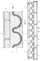
- Figure 1 illustrates the section of a fragment of panel for the construction industry, which in the present example, constitutes a roof or tiling of Arabian tiles, obtained according to the invention.
- the mould surface of mould 1 which is the surface onto which the moulding materials must be applied, is shaped to complement the main surface of the solid body to be obtained; in the present description, reference is made to this mould surface by means of the expression, negative mould surface of the main surface of the solid body to be obtained.
- the main surface of the solid body to be obtained is either the surface intended to be visible (in the case of a tiling) or the functional surface, which in the case of a conduit would be the surface on which the liquid (or other material) runs.
- this second layer 3 contains an abundant quantity of cut fibre, it behaves likes felt and/or protective felt, which absorbs the impact of the coarse aggregates of a third resistant layer 4 of base concrete to be teemed onto the second layer 3, and prevents such coarse aggregates from pervading to the main surface of the panel, through the first layer 2 that constitutes said main surface, which on the one hand, would degrade the desired aesthetic effect, and on the other hand, could damage the surface of the mould 1.
- the third layer 4 of base concrete includes, preferably, a reinforced metallic structure 5, preferably made from right-angled mesh, which is placed in the mould 1 before, during or after the base concrete is provided onto the free surface of the second layer 3.
- the metallic structure 5 is placed, according to standards, at a distance no less than 30 mm from the free surface of the third resistant layer 4 of concrete.
- Figure 2 illustrates a mould 1, which is full to produce a panel for the construction industry like the one illustrated partially in section in Figure 1.
- Figure 2 shows the negative mould 1 which is used to obtain an imitated surface of a stylised tiling composed of Arabian tiles, having the technical and aesthetic features to build a roof for a building, whether or not the building be constructed with outdoor walls and/or indoor walls built with panels made in accordance with the invention.
- the mould 1, illustrated therein as an example is supported on a rigid base 6 formed by panels 6a and 6b associated by a series of small beams 6c.
- the upper part of the edge of the mould 1 has vertical walls 7, removable, movable or foldable, which constitute the side cuts of the actual mould.
- These rigid bases 6 which are self-supporting and level adjustable are on trolleys, not shown, which can run on rails or the like.
- the vertical walls 7 can be provided with means for positioning the metallic reinforcement structure 5 of the third resistant layer 4 of base concrete when same is teemed.
- a possible formulation for the fine mortar cement forming the first impermeable layer 2, or visible surface or functional surface of the panel, is that exposed below: Material Parts by weight Portland cement 38 Fine sand 38 Polymer 5 Water 15 Superflux 1 Pigment 3 these materials are mixed and homogenised in a stirrer at high speed, and a first, homogenous and impermeable layer 2 of the resulting fine mortar mass is applied onto the mould 1.
- the fine mortar cement is prepared adding a fibril reinforcement to form the second layer 3.
- the base concrete consists of a normal aggregate concrete that can be made "in situ” or acquired from a cementing station, to form the third layer 4.
- the first 2 and second 3 layers are applied by projection, so as to achieve an even, finer thickness, while the third 4 layer is deposited by teeming, filling the whole mould including the metallic reinforcement structure 5.
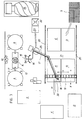
- Figure 3 shows one of the possible, suitable arrangements of the plant for the practical embodiment of the process.
- the plant comprises a storage area for the materials, as can be seen in Figure 4, which includes a silo 8 for the cement, a silo 9 for the fine aggregate and three cisterns 10 for the water, polymer and the superflux.
- These silos 8 and 9 and the cisterns 10 are provided with transferring and metering means, such as transport screws 11, hoppers 12, chisel valves 13, scales , flow meters, etc. automated by a computer.
- the different materials are poured into a homogenising stirring apparatus 14 at high speed and, once the mixture is formed, said apparatus discharges it into the tank 15 of a driving pump 16 ( Figure 3), which transfers the fine mortar cement through a conduit 17 as far as an omni-directional projection nozzle 18 movably mounted on a portal frame 19.
- the portal frame 19 runs, by means of motorised running-boards, on rails 20 situated in parallel to each other on both sides of an area 21 where the moulds are housed mounted on the rigid bases 6.
- both the portal frame 19 and the rigid bases 6 can be mobile, or only one of them can be, preferably, the portal frame 19.
- the plant also comprises a base concrete kneader 22, associated with a pump for concrete 23 which receives the concrete from the concrete mixer-truck 24 which is teemed onto the second layer 3 acting as an absorbent barrier to complete the actual mould 1, covering the metallic reinforcement structure 5.
- a hinged tubular arm 25 is used to deposit the cement and said arm ends in the pouring nozzle, placed next to the omni-directional projection nozzle 18.
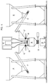
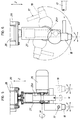
- Figures 5 and 6 show an example of the embodiment of the omni-directional projection nozzle 18, which is mounted on a counterweighted arm 25a, which rotates around an axis M by the action of an electric motor 26 (both mounted in a fork-shaped support 27), which rotates around an axis N by the action of an electric motor 28 which, in turn, is installed in a support column 29 associated with the portal frame 19 by means of a truck 30 (see Figures 3, 7 and 8).
- This truck 30 can move longitudinally on the portal frame 19, around the system's Y axis by the action of the geared motor 31, so that the support column 29 is suitable for moving vertically in the direction of the system's Z axis by the action of the electric motor 32 and the geared motor 32a, at the same time that the truck 30, subject to the movement of the portal frame 19 in the direction of the system's X axis, is also capable of moving in that direction.
- the portal frame 19 moves on the guide rails 33 supported on pillars 34 in the direction of the X axis by the action of a geared motor 35.
- the electric power of the different geared motors 31 and 35, electric motors 26, 28 and 32, as well as the electric mechanisms (ends of stroke, sensors, etc. ) is provided through flexible cables housed in hinged trays 36 made of insulating material.
- the Portland cement and the fine aggregate are metered from the silos 8 and 9 and, together with the water, supplied from the mains or from one of the cisterns 10, the polymer and the superflux, also supplied from the other cisterns 10, are all put into the high speed homogenising stirring apparatus 14, from which the fine mortar cement mixture, once it is made, is discharged into the tank 15 associated with the driving pump 16 which leads the mixture forming the first fluid material, as far as the omni-directional projection nozzle 18, which evenly projects the mixture onto the mould 1, passing over it successively, crosswise, longitudinally, diagonally and in other directions, enabled by the movement of the portal frame 19, on its own, or in combination with the movement of the projection nozzle 18 along said portal frame, until the first, homogenous and impermeable layer 2 is formed defining the main surface of the panel for the construction industry.
- the second layer 3, or absorbent barrier (forming the second fluid material) is deposited, which comprises the same fine mortar cement as the first layer 2, from which the colouring and the polymer can be omitted, and in which the mortar can incorporate the fibril reinforcement consisting of fibres, cut "in situ" in the actual omni-directional projection nozzle 18 by means of a guillotine attached thereto, from bundles of filaments that reach therein from an exterior coil.
- the fibril reinforcement can be added in the form of fibre cut in the stirrer 14, or in the tank 15, and mixed with the fine mortar cement before it is fed into the driving pump 16.
- the fibril reinforcement can also be constituted by continuous filaments, fabric, non-woven fabric, laps, lap robe, mesh, etc.
- the third resistant layer 4 of base concrete is deposited onto the absorbent barrier layer 3 by means of the driving of the pump for concrete 23 and the crosswise movement of the hinged tubular arm 25 as far as the pouring nozzle, placed next to the omni-directional projection nozzle 18, which describes the same basic movements as the omni-directional projection nozzle 18.
- the third resistant layer 4 completes the service volume of the actual mould 1, covering the metallic reinforcement structure 5.
- the plant in Figure 3 shows some square-shaped spaces corresponding to the position of the moulds in the different operational phases, where A corresponds to the mould's position during the projection of the first layer of fine mortar; B corresponds to the position of the projection of the fine mortar with fibre onto a mould onto which the first layer of fine mortar has already been deposited; C corresponds to the depositing of the third resistant layer 4 of base concrete; D corresponds to the positioning of the metallic reinforcement structure 5 not formed of right-angled mesh; E corresponds to the stacking position of the mould 1 and the panel's heat curing position by means of the panel's heating equipment e ; F corresponds to the turning and form removal phase and G corresponds to the stacking position and wet post-curing position.
- the arrow H indicates the direction in which the full mould exits the moulding area.
- the order, distribution and number of such square spaces depend on the size of the panel to be obtained and on the way that the application sequence of the various layers has to be carried out in each case, which will vary if there is only one mould, two or more.
- the moulded body can comprise electrical or fluid conduits and have openings for doors and windows, as well as ensemble arrangements with other elements and means for the handling thereof.
- a form removal arrangement comprising a structure from which at least two flexible rings hang, such as belts, slings, etc., mounted on respective motorised pulleys, which clasp the mould and obtained panel, with sufficient clearance and, by the action of the pulleys, allow the assembly to turn over and said panel to be removed by gravity.
Landscapes
- Engineering & Computer Science (AREA)
- Chemical & Material Sciences (AREA)
- Ceramic Engineering (AREA)
- Mechanical Engineering (AREA)
- Manufacturing & Machinery (AREA)
- Architecture (AREA)
- Civil Engineering (AREA)
- Structural Engineering (AREA)
- Manufacturing Of Tubular Articles Or Embedded Moulded Articles (AREA)
Applications Claiming Priority (1)
| Application Number | Priority Date | Filing Date | Title |
|---|---|---|---|
| PCT/ES1997/000192 WO1999004945A1 (es) | 1997-07-28 | 1997-07-28 | Procedimiento para moldear un cuerpo solido, monopieza y abierto, con materiales fluidos endurecibles al aire, un cuerpo asi obtenido y una instalacion para su realizacion |
Publications (1)
| Publication Number | Publication Date |
|---|---|
| EP0928672A1 true EP0928672A1 (de) | 1999-07-14 |
Family
ID=8298062
Family Applications (1)
| Application Number | Title | Priority Date | Filing Date |
|---|---|---|---|
| EP97932847A Withdrawn EP0928672A1 (de) | 1997-07-28 | 1997-07-28 | Verfahren zum formen eines einstückigen offenen festkörpers mit lufthärtenden flüssigmaterialien, so hergestellter körper und anlage zur herstellung solcher körper |
Country Status (3)
| Country | Link |
|---|---|
| EP (1) | EP0928672A1 (de) |
| AU (1) | AU3624097A (de) |
| WO (1) | WO1999004945A1 (de) |
Cited By (1)
| Publication number | Priority date | Publication date | Assignee | Title |
|---|---|---|---|---|
| WO2005108042A1 (en) * | 2004-04-29 | 2005-11-17 | Keystone Retaining Wall Systems, Inc. | Composite capping block |
Families Citing this family (1)
| Publication number | Priority date | Publication date | Assignee | Title |
|---|---|---|---|---|
| ES2575225B1 (es) * | 2016-04-06 | 2017-04-06 | Carlos Fradera Pellicer | Procedimiento de fabricación de paneles de mortero de cemento pretensados con una etapa de llenado robotizada, e instalación correspondiente |
Family Cites Families (6)
| Publication number | Priority date | Publication date | Assignee | Title |
|---|---|---|---|---|
| FR2540033B1 (fr) * | 1983-01-27 | 1988-05-06 | Humarbo France | Procede et dispositif de fabrication en continu de produits moules en beton ou analogues |
| DK454283A (da) * | 1983-09-30 | 1985-03-31 | Eternit Fab Dansk As | Tagplade, fremgangsmaade til fremstilling af samme, samt taetningsbaand til en saadan tagplade |
| GB8416874D0 (en) * | 1984-07-03 | 1984-08-08 | Mcneil A | Building panel |
| WO1993003238A1 (en) * | 1991-08-02 | 1993-02-18 | Daiken Trade & Industry Co., Ltd | Inorganic constructional board and method of manufacturing the same |
| JP3015628B2 (ja) * | 1993-06-30 | 2000-03-06 | 日本プレストン株式会社 | 転写型化粧シートとその製造方法 |
| ES1034840Y (es) * | 1996-08-01 | 1997-07-01 | Pellicer Carlos F | Panel para cerramiento interior de edificaciones. |
-
1997
- 1997-07-28 EP EP97932847A patent/EP0928672A1/de not_active Withdrawn
- 1997-07-28 WO PCT/ES1997/000192 patent/WO1999004945A1/es not_active Application Discontinuation
- 1997-07-28 AU AU36240/97A patent/AU3624097A/en not_active Abandoned
Non-Patent Citations (1)
| Title |
|---|
| See references of WO9904945A1 * |
Cited By (1)
| Publication number | Priority date | Publication date | Assignee | Title |
|---|---|---|---|---|
| WO2005108042A1 (en) * | 2004-04-29 | 2005-11-17 | Keystone Retaining Wall Systems, Inc. | Composite capping block |
Also Published As
| Publication number | Publication date |
|---|---|
| AU3624097A (en) | 1999-02-16 |
| WO1999004945A1 (es) | 1999-02-04 |
Similar Documents
| Publication | Publication Date | Title |
|---|---|---|
| US9649662B2 (en) | Seamless reinforced concrete structural insulated panel | |
| US5202132A (en) | Production line equipment to manufacture large concrete panels | |
| US4799982A (en) | Method of molding monolithic building structure | |
| US7794825B2 (en) | Prefabricated lightweight concrete structure including columns | |
| CN107297810A (zh) | 一种预制墙体构件的制作及安装方法 | |
| CN1269859A (zh) | 用于建筑物的墙的改进的模板 | |
| JP2003504541A (ja) | 建築パネル及びその製造設備 | |
| EP0928672A1 (de) | Verfahren zum formen eines einstückigen offenen festkörpers mit lufthärtenden flüssigmaterialien, so hergestellter körper und anlage zur herstellung solcher körper | |
| KR100974424B1 (ko) | 보도용 대형 패널블럭 | |
| CN110869568A (zh) | 通用和专用工业化建筑系统中用于建筑通风的钢筋混凝土墙模块的改进 | |
| JPH06122540A (ja) | セメント結合による透水性板材およびその製造方法 | |
| AU2004241359B2 (en) | Building block | |
| CN113565236A (zh) | 一种装饰性室内夯土柱的制作工艺 | |
| KR100562345B1 (ko) | 건축용 경량 마감재 및 그 제조방법 | |
| CN210282686U (zh) | 一种混凝土路面砖养护装置 | |
| CN211622250U (zh) | 一种内墙板 | |
| AU2004202568B2 (en) | Fiber cement construction panel | |
| RU2204477C2 (ru) | Способ изготовления изделия с декоративной поверхностью и изделие с декоративной поверхностью | |
| CN113530085A (zh) | 一种室内夯土柱与grg顶面一体式施工工艺 | |
| CN113585549A (zh) | 一种室内装饰夯土柱浇筑装置 | |
| CN116175780A (zh) | 一种玻璃纤维增强水泥复合混凝土预制建筑构件的生产方法 | |
| SU1350026A1 (ru) | Форма дл изготовлени изделий из бетонных смесей | |
| CN114837358A (zh) | 屋面泛水位置安装的弧形预制件的预制及铺贴方法 | |
| CN113565208A (zh) | 一种室内夯土柱一体式连接系统 | |
| CN115787825A (zh) | 一种不规则异曲面柱廊工程施工方法 |
Legal Events
| Date | Code | Title | Description |
|---|---|---|---|
| PUAI | Public reference made under article 153(3) epc to a published international application that has entered the european phase |
Free format text: ORIGINAL CODE: 0009012 |
|
| 17P | Request for examination filed |
Effective date: 19990422 |
|
| AK | Designated contracting states |
Kind code of ref document: A1 Designated state(s): DE FR GB IT PT |
|
| 17Q | First examination report despatched |
Effective date: 20020219 |
|
| GRAH | Despatch of communication of intention to grant a patent |
Free format text: ORIGINAL CODE: EPIDOS IGRA |
|
| STAA | Information on the status of an ep patent application or granted ep patent |
Free format text: STATUS: THE APPLICATION IS DEEMED TO BE WITHDRAWN |
|
| 18D | Application deemed to be withdrawn |
Effective date: 20030108 |