EP0928623A2 - Vorrichtung zur Regenerierung einer Bremse, insbesondere für Rollschuhe - Google Patents
Vorrichtung zur Regenerierung einer Bremse, insbesondere für Rollschuhe Download PDFInfo
- Publication number
- EP0928623A2 EP0928623A2 EP98124823A EP98124823A EP0928623A2 EP 0928623 A2 EP0928623 A2 EP 0928623A2 EP 98124823 A EP98124823 A EP 98124823A EP 98124823 A EP98124823 A EP 98124823A EP 0928623 A2 EP0928623 A2 EP 0928623A2
- Authority
- EP
- European Patent Office
- Prior art keywords
- pad
- ground
- interacts
- support
- wings
- Prior art date
- Legal status (The legal status is an assumption and is not a legal conclusion. Google has not performed a legal analysis and makes no representation as to the accuracy of the status listed.)
- Withdrawn
Links
- 230000001172 regenerating effect Effects 0.000 title claims abstract description 5
- 230000009471 action Effects 0.000 claims description 9
- 230000004048 modification Effects 0.000 abstract description 3
- 238000012986 modification Methods 0.000 abstract description 3
- 230000007423 decrease Effects 0.000 description 3
- 230000000694 effects Effects 0.000 description 3
- 230000003213 activating effect Effects 0.000 description 2
- 230000003993 interaction Effects 0.000 description 2
- 230000004913 activation Effects 0.000 description 1
- 230000000670 limiting effect Effects 0.000 description 1
- 238000004519 manufacturing process Methods 0.000 description 1
Images



Classifications
-
- A—HUMAN NECESSITIES
- A63—SPORTS; GAMES; AMUSEMENTS
- A63C—SKATES; SKIS; ROLLER SKATES; DESIGN OR LAYOUT OF COURTS, RINKS OR THE LIKE
- A63C17/00—Roller skates; Skate-boards
- A63C17/14—Roller skates; Skate-boards with brakes, e.g. toe stoppers, freewheel roller clutches
- A63C17/1436—Roller skates; Skate-boards with brakes, e.g. toe stoppers, freewheel roller clutches contacting the ground
Definitions
- the present invention relates to a device for regenerating a brake, particularly for skates.
- US-337,161 discloses a skate which is provided with a shoe supporting plate having two lower supports for two pairs of mutually parallel wheels.
- a support for a brake is associated at the rear pair of wheels; the brake is constituted by a pad, having a surface which interacts with the ground and which is generally made of rubber-like material.
- the position of the pad can be adjusted by means of a screw which reduces the distance of the surface of the pad from the facing ground.
- a drawback of this conventional type is that as the pad gradually wears, the user must remove the skate and operate the screw, pushing the pad so that it returns closer to the ground.
- the need to restore the initial condition of the pad, and therefore its position with respect to the ground at a preset height, is in any case indispensable in order to ensure that the user achieves optimum braking.
- US-3,112,120 discloses a skate in which the threaded stem of a brake, provided with a pad towards the ground, is rotatably associated in the rear region of the shoe supporting plate, adjacent to the pair of rear wheels.
- An adjustment washer is associated with the threaded stem; as in the previously illustrated case, during the use of the skate the pad wears at the region that interacts with the ground: as the thickness of the pad, and accordingly the distance of the pad from the ground, decreases, the user is forced to stop his other sports activity, optionally remove the skate to perform the operation more easily, and turn the pad so as to move it closer to the ground; the position can be determined by the adjustment washer.
- US-5,197,572 discloses a skate provided with a brake comprising a support for a pad.
- the brake further comprises an element for fixing and adjusting the support which is accordingly connected between the wheel pivoting frame and the pad support.
- Adjustment occurs by means of the interaction between two toothed surfaces formed on the pad support and on the support fixing and adjustment element. This position can be preset by means of a screw, thus allowing the user to move the pad closer to the ground whenever required by gradual wear.
- this skate also suffers the above-mentioned drawbacks, since this adjustment must be performed by the user whenever he detects a decrease in the braking effect and because this adjustment must be performed by interrupting sports practice, optionally removing the skate and using suitable tools.
- US-5,192,099 discloses a skate provided with a supporting frame for in-line wheels which has, at its rear end, two tabs for the pivoting of the last rear wheel; said tabs can move elastically closer to the overlying part of the frame when the user shifts his weight backward.
- the braking action is achieved because a pad is arranged transversely to the frame in the region above the last wheel and therefore interacts with the wheel when the skate is tilted backward.
- the pad In order to compensate for the wear of the pad, the pad is associated with a system for adjusting its vertical position which however, like the previously described skates, requires manual intervention of the user.
- US-5,348,320 discloses a skate which comprises a supporting frame for mutually in-line wheels, to the rear of which the support for a pad which interacts with the ground during braking is slidingly associated.
- connection between the wheel support and the pad support is adjustable, in that there is a screw whose tightening locks two complementarily toothed surfaces formed respectively on the pad support and on the wheel support.
- the aim of the present invention is to solve the above-mentioned problems, eliminating the drawbacks of the cited prior art and thus providing an invention which allows the user to always achieve the braking action in optimum conditions even as the degree of wear of the braking element that interacts with the ground varies.
- An important object is to provide an invention which allows to achieve, over time, a constantly optimum braking action without requiring the user to temporarily suspend sports practice or to intervene directly to restore the optimum conditions.
- a further important object is to provide an invention which allows to keep the effectiveness of the braking action constant over time and to extend the life of the braking element.
- a further object is to provide an invention which is reliable and safe in use and has low manufacturing costs.
- a device for regenerating a brake, particularly for skates comprising a supporting frame for a plurality of wheels, a pad or block being associated, in a rear region, with said frame, said pad having a surface which is initially intact and interacts with the ground during braking, characterized in that a sensor for detecting the degree of wear of said surface of said pad is connected to a means which is adapted to modify the initial position of said pad.
- this modification of the initial position of said pad or block is achieved by restoring an intact condition for said surface that interacts with the ground.
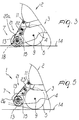
- 1 designates the device, which is particularly usable for skates of the type comprising a shoe 2 below which a preferably U-shaped frame 3 is associated.
- a plurality of mutually in-line wheels 5 are pivoted between the first wings 4 of said frame.
- a support 6 for a pad or block 7 is associated at the rear end of the frame 3 and has a box-like shape which forms a pair of second wings 8 which are pivoted, at one end, at the first pivot 9 for supporting the last wheel 5 of the skate.
- the support 6 has a pair of third wings 10a, 10b which are associated with the shoe or with a tab which protrudes from the frame by means of a suitable second pivot 11.
- the pad or block 7 is pivoted between the first wings 4 of the support 6, in a region to the rear of the last rear wheel 5, by means of a suitable third pivot or screw 12 with respect whereto the pad or block can turn.
- the pad or block has a polygonal plan shape and therefore has a plurality of preferably flat surfaces 13 which are adapted to interact with the ground 14.
- a sensor for detecting the degree of wear of each one of the surfaces 13 is associated with the support 6 and is constituted by a disk 15 which is arranged coaxially to the third pivot or screw 12 at at least one side of the pad or block 7.
- the disk 15 has an essentially annular shape, with a central hole whose diameter is several times larger than the diameter of the third pivot or screw 12.
- a body 16 can be arranged in the hole and is provided with a protrusion or raised portion 16a which is rigidly coupled to said body and in which there is a slot 17 in which said third pivot or screw 12 passes.
- Slot 17 is essentially vertical with respect to the ground 14 in the condition in which the braking action is not activated, as shown in Figure 2, while the raised portion 16a is accommodated within a recessed seat 6a formed inside the support 6. This refinement allows the body 16 to slide exclusively in a vertical direction with respect to the support 6, since rotation is locked by the interaction between the raised portion 16a and the walls of the recessed seat 6a.
- a sprocket 18 is arranged on the opposite side with respect to said body and said disk, rotates rigidly with the pad or block 7 and has a plurality of teeth 19 which selectively interact by abutment with a pair of tabs 20a and 20b which protrude from a pawl 21 which is rotatably associated between the shoulders 8 by means of a fourth pivot 22 and oscillates in contrast with a flexible element such as a spring 23 which is interposed between said pawl and a base 24 located inside said support 6 in a region above the adjacent wheel 5.
- the arrangement of the teeth is such as to block a clockwise rotation of the pad 7 during the normal braking action and therefore when the surface that interacts with the ground is not worn.
- the configuration of said disk 15, said body 16, said slot 17, said sprocket 18, said teeth 19 and said tabs 20a and 20b is such that they are not actively involved during braking in the condition in which the surface 13 that interacts with the ground is not worn beyond a certain threshold.
- each one of the disks 15 interacts with the ground, and as the surface of the pad wears, the disk 15 and the body 16 provided with the slot 17 simultaneously move vertically.
- the disk has disengaged the ends of the tabs 20a and 20b from the respective tooth 19, thus allowing the free clockwise rotation of the pad 7 until, as shown in Figure 5, the worn surface 26 of the pad 7 is turned through an angle which again directs toward the ground 14 a further intact surface 13.
- the ends of the tabs 20a and 20b reengage a corresponding tooth 19.
- the invention has achieved the intended aim and objects, a device having been provided which allows, in a fully automatic manner and therefore sparing the user from any action, to always achieve an optimum braking condition, since as the surface that was initially termed intact and interacts with the ground wears, the pad rotates, restoring the initial optimum conditions, presenting again a new intact surface which makes contact with the ground.
- the invention further allows a longer life of the pad, since all the surfaces formed thereon are utilized before considering its replacement.
- a decrease in the degree of inclination of the skate that determines the braking action when a certain degree of wear of the pad is exceeded is also noted.
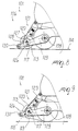
- Figures 6 to 9 illustrate another embodiment of a device 101 in which the tabs 120 of the pawl 121 are lifted by means of a cam 127 which protrudes at the upper perimetric edge 128 of two fourth wings 129 which are arranged laterally to the support 106 and are freely pivoted, at one end, at the first pivot 109 and are transversely connected, at the other end, by a suitable sensor which is constituted by a roller 130 which is freely rotatably pivoted between them and interacts with the ground 114.
- the cam 127 is formed at the region that lies above a slot 117 formed in said fourth wings 129.
- the worn surface 126 of said pad rotates, repositioning at the underlying ground 114 a new intact surface 113, the different height of which allows the pawl 121 to again mesh with one of the teeth 119, which is forced to do so by the presence of the spring 123.
- This embodiment also allows to achieve the intended aim and objects.
Landscapes
- Braking Arrangements (AREA)
- Transition And Organic Metals Composition Catalysts For Addition Polymerization (AREA)
- Separation, Recovery Or Treatment Of Waste Materials Containing Plastics (AREA)
- Footwear And Its Accessory, Manufacturing Method And Apparatuses (AREA)
Applications Claiming Priority (2)
| Application Number | Priority Date | Filing Date | Title |
|---|---|---|---|
| ITTV980001 | 1998-01-09 | ||
| IT98TV000001A ITTV980001A1 (it) | 1998-01-09 | 1998-01-09 | Dispositivo per la rigenerazione di un freno, particolarmente per patt ini |
Publications (2)
| Publication Number | Publication Date |
|---|---|
| EP0928623A2 true EP0928623A2 (de) | 1999-07-14 |
| EP0928623A3 EP0928623A3 (de) | 2000-04-12 |
Family
ID=11420300
Family Applications (1)
| Application Number | Title | Priority Date | Filing Date |
|---|---|---|---|
| EP98124823A Withdrawn EP0928623A3 (de) | 1998-01-09 | 1998-12-30 | Vorrichtung zur Regenerierung einer Bremse, insbesondere für Rollschuhe |
Country Status (3)
| Country | Link |
|---|---|
| US (1) | US6199668B1 (de) |
| EP (1) | EP0928623A3 (de) |
| IT (1) | ITTV980001A1 (de) |
Cited By (1)
| Publication number | Priority date | Publication date | Assignee | Title |
|---|---|---|---|---|
| US6199668B1 (en) * | 1998-01-09 | 2001-03-13 | Benetton Group S.P.A. | Device for regenerating a brake particularly for skates |
Families Citing this family (5)
| Publication number | Priority date | Publication date | Assignee | Title |
|---|---|---|---|---|
| US6505713B1 (en) * | 2000-08-24 | 2003-01-14 | Rite-Hite Holding Corporation | Tire locating wheel restraint |
| US8307956B2 (en) * | 2007-07-25 | 2012-11-13 | Rite-Hite Holding Corporation | Wheel chock system |
| US8006811B2 (en) | 2007-09-07 | 2011-08-30 | Rite-Hite Holding Corporation | Loading dock wheel restraint comprising a flexible elongate member |
| US8464846B2 (en) | 2008-03-04 | 2013-06-18 | Rite-Hite Holding Corporation | Restraining arms for wheel chocks |
| US8286757B2 (en) | 2010-07-09 | 2012-10-16 | Rite-Hite Holding Corporation | Wheel chock system |
Citations (2)
| Publication number | Priority date | Publication date | Assignee | Title |
|---|---|---|---|---|
| US3112120A (en) | 1962-03-14 | 1963-11-26 | Chicago Roller Skate Co | Toe stop |
| US5197572A (en) | 1991-04-25 | 1993-03-30 | Roberts Jeffrey A | In-line skate brake system |
Family Cites Families (11)
| Publication number | Priority date | Publication date | Assignee | Title |
|---|---|---|---|---|
| US2191018A (en) * | 1937-10-01 | 1940-02-20 | Ickenroth Anthony | Roller skate brake |
| US5052701A (en) * | 1989-08-23 | 1991-10-01 | Rollerblade, Inc. | Roller skate with pivoting brake |
| US5465984A (en) * | 1992-04-29 | 1995-11-14 | Nordica S.P.A. | Braking device particularly for skates |
| ES2092169T3 (es) * | 1992-04-29 | 1996-11-16 | Nordica Spa | Dispositivo de frenado para patines. |
| ES2114996T3 (es) * | 1992-11-30 | 1998-06-16 | Benetton Sportsystem Spa | Patin de ruedas con dispositivo de frenado. |
| US5375859A (en) * | 1993-08-26 | 1994-12-27 | David G. Peck | Mechanical brake for in-line roller skate |
| CA2122526A1 (en) * | 1994-04-29 | 1995-10-30 | Scott Harkness | Roller skate brake assembly |
| IT1273890B (it) * | 1994-05-23 | 1997-07-11 | Nordica Spa | Struttura di dispositivo frenante, particolarmente per pattini. |
| IT1273902B (it) * | 1994-06-13 | 1997-07-11 | Nordica Spa | Struttura di dispositivo frenante, particolarmente per pattini ad attivazione migliorata |
| AU6377896A (en) * | 1995-07-14 | 1997-02-18 | First Team Sports, Inc | Adjustable roller brake system |
| ITTV980001A1 (it) * | 1998-01-09 | 1999-07-09 | Benetton Sportsystem Spa | Dispositivo per la rigenerazione di un freno, particolarmente per patt ini |
-
1998
- 1998-01-09 IT IT98TV000001A patent/ITTV980001A1/it unknown
- 1998-12-30 EP EP98124823A patent/EP0928623A3/de not_active Withdrawn
-
1999
- 1999-01-04 US US09/225,235 patent/US6199668B1/en not_active Expired - Fee Related
Patent Citations (2)
| Publication number | Priority date | Publication date | Assignee | Title |
|---|---|---|---|---|
| US3112120A (en) | 1962-03-14 | 1963-11-26 | Chicago Roller Skate Co | Toe stop |
| US5197572A (en) | 1991-04-25 | 1993-03-30 | Roberts Jeffrey A | In-line skate brake system |
Cited By (1)
| Publication number | Priority date | Publication date | Assignee | Title |
|---|---|---|---|---|
| US6199668B1 (en) * | 1998-01-09 | 2001-03-13 | Benetton Group S.P.A. | Device for regenerating a brake particularly for skates |
Also Published As
| Publication number | Publication date |
|---|---|
| ITTV980001A0 (it) | 1998-01-09 |
| EP0928623A3 (de) | 2000-04-12 |
| US6199668B1 (en) | 2001-03-13 |
| ITTV980001A1 (it) | 1999-07-09 |
Similar Documents
| Publication | Publication Date | Title |
|---|---|---|
| US5486011A (en) | Spring biased braking device for in-line roller skates | |
| US5242035A (en) | Caster with pivotable two-armed wheel brake | |
| EP0414522A1 (de) | Rollschuh | |
| US5183275A (en) | Brake for in-line roller skate | |
| US2905275A (en) | Caster brake | |
| EP0877176B1 (de) | Scheibenbremsdesign zur Verhindergung von Klappergeraüschen | |
| EP0518694B1 (de) | Langsam anziehende Bremse für einen Rollschuh | |
| US6199668B1 (en) | Device for regenerating a brake particularly for skates | |
| CA2135364A1 (en) | In-line skate | |
| JPS6045544B2 (ja) | スキ−ビンデイング用のトウ当接装置 | |
| WO2007070401A2 (en) | Vertically reciprocating skate brake | |
| EP1867368B1 (de) | Rollschuhanordnung mit Bremsvorrichtung | |
| EP0815906B1 (de) | Rollschuh mit Bremskontrolleinrichtung | |
| TWI702158B (zh) | 用於車輛座椅的傾斜裝置 | |
| WO1993005854A1 (en) | In-line skate brake system | |
| US6131922A (en) | Roller skate brake arrangement | |
| WO2005014126A1 (en) | Snowboard binding | |
| EP1092455B1 (de) | Bindung für Snowboardstiefel | |
| KR20100066203A (ko) | 의자의 머리받침 조절 장치 | |
| EP0687487A2 (de) | Bremsvorrichtung, insbesondere für Rollschuhe | |
| US4560137A (en) | Positioning device for a supported article | |
| US4844212A (en) | Mechanically actuated brake with automatic adjustment | |
| EP1023847B1 (de) | Einstellvorrichtung für Sportschuhe | |
| JP2002085469A (ja) | 車椅子 | |
| US6425588B1 (en) | Safety brake for in-line skates |
Legal Events
| Date | Code | Title | Description |
|---|---|---|---|
| PUAI | Public reference made under article 153(3) epc to a published international application that has entered the european phase |
Free format text: ORIGINAL CODE: 0009012 |
|
| AK | Designated contracting states |
Kind code of ref document: A2 Designated state(s): DE FR IT |
|
| AX | Request for extension of the european patent |
Free format text: AL;LT;LV;MK;RO;SI |
|
| PUAL | Search report despatched |
Free format text: ORIGINAL CODE: 0009013 |
|
| AK | Designated contracting states |
Kind code of ref document: A3 Designated state(s): AT BE CH CY DE DK ES FI FR GB GR IE IT LI LU MC NL PT SE |
|
| AX | Request for extension of the european patent |
Free format text: AL;LT;LV;MK;RO;SI |
|
| 17P | Request for examination filed |
Effective date: 20000925 |
|
| AKX | Designation fees paid |
Free format text: DE FR IT |
|
| STAA | Information on the status of an ep patent application or granted ep patent |
Free format text: STATUS: THE APPLICATION IS DEEMED TO BE WITHDRAWN |
|
| 18D | Application deemed to be withdrawn |
Effective date: 20020702 |