EP0928037A1 - Battery device - Google Patents
Battery device Download PDFInfo
- Publication number
- EP0928037A1 EP0928037A1 EP98904394A EP98904394A EP0928037A1 EP 0928037 A1 EP0928037 A1 EP 0928037A1 EP 98904394 A EP98904394 A EP 98904394A EP 98904394 A EP98904394 A EP 98904394A EP 0928037 A1 EP0928037 A1 EP 0928037A1
- Authority
- EP
- European Patent Office
- Prior art keywords
- connection member
- connection
- circuit board
- battery device
- battery
- Prior art date
- Legal status (The legal status is an assumption and is not a legal conclusion. Google has not performed a legal analysis and makes no representation as to the accuracy of the status listed.)
- Granted
Links
- HBBGRARXTFLTSG-UHFFFAOYSA-N Lithium ion Chemical compound [Li+] HBBGRARXTFLTSG-UHFFFAOYSA-N 0.000 claims abstract description 27
- 229910001416 lithium ion Inorganic materials 0.000 claims abstract description 27
- 230000005611 electricity Effects 0.000 claims description 5
- 230000000694 effects Effects 0.000 claims description 3
- 239000002861 polymer material Substances 0.000 claims description 2
- 238000005452 bending Methods 0.000 claims 1
- 230000008602 contraction Effects 0.000 description 7
- 230000001965 increasing effect Effects 0.000 description 7
- PXHVJJICTQNCMI-UHFFFAOYSA-N Nickel Chemical compound [Ni] PXHVJJICTQNCMI-UHFFFAOYSA-N 0.000 description 4
- 208000016261 weight loss Diseases 0.000 description 3
- 150000001875 compounds Chemical class 0.000 description 2
- 238000007599 discharging Methods 0.000 description 2
- 239000007772 electrode material Substances 0.000 description 2
- 230000006872 improvement Effects 0.000 description 2
- 239000000463 material Substances 0.000 description 2
- 239000000203 mixture Substances 0.000 description 2
- 229910052759 nickel Inorganic materials 0.000 description 2
- OKTJSMMVPCPJKN-UHFFFAOYSA-N Carbon Chemical compound [C] OKTJSMMVPCPJKN-UHFFFAOYSA-N 0.000 description 1
- RYGMFSIKBFXOCR-UHFFFAOYSA-N Copper Chemical compound [Cu] RYGMFSIKBFXOCR-UHFFFAOYSA-N 0.000 description 1
- 229910032387 LiCoO2 Inorganic materials 0.000 description 1
- WHXSMMKQMYFTQS-UHFFFAOYSA-N Lithium Chemical compound [Li] WHXSMMKQMYFTQS-UHFFFAOYSA-N 0.000 description 1
- 239000004743 Polypropylene Substances 0.000 description 1
- XAGFODPZIPBFFR-UHFFFAOYSA-N aluminium Chemical compound [Al] XAGFODPZIPBFFR-UHFFFAOYSA-N 0.000 description 1
- 229910052782 aluminium Inorganic materials 0.000 description 1
- 230000015572 biosynthetic process Effects 0.000 description 1
- 229910052799 carbon Inorganic materials 0.000 description 1
- 230000008859 change Effects 0.000 description 1
- 239000011889 copper foil Substances 0.000 description 1
- 230000003247 decreasing effect Effects 0.000 description 1
- 238000010586 diagram Methods 0.000 description 1
- 230000002708 enhancing effect Effects 0.000 description 1
- 239000011888 foil Substances 0.000 description 1
- 229910052744 lithium Inorganic materials 0.000 description 1
- 238000004519 manufacturing process Methods 0.000 description 1
- 238000000034 method Methods 0.000 description 1
- -1 polypropylene Polymers 0.000 description 1
- 229920001155 polypropylene Polymers 0.000 description 1
- 239000011148 porous material Substances 0.000 description 1
- 230000008569 process Effects 0.000 description 1
- 239000013585 weight reducing agent Substances 0.000 description 1
Images




Classifications
-
- H—ELECTRICITY
- H01—ELECTRIC ELEMENTS
- H01M—PROCESSES OR MEANS, e.g. BATTERIES, FOR THE DIRECT CONVERSION OF CHEMICAL ENERGY INTO ELECTRICAL ENERGY
- H01M10/00—Secondary cells; Manufacture thereof
- H01M10/04—Construction or manufacture in general
- H01M10/0413—Large-sized flat cells or batteries for motive or stationary systems with plate-like electrodes
-
- H—ELECTRICITY
- H01—ELECTRIC ELEMENTS
- H01M—PROCESSES OR MEANS, e.g. BATTERIES, FOR THE DIRECT CONVERSION OF CHEMICAL ENERGY INTO ELECTRICAL ENERGY
- H01M10/00—Secondary cells; Manufacture thereof
- H01M10/42—Methods or arrangements for servicing or maintenance of secondary cells or secondary half-cells
- H01M10/425—Structural combination with electronic components, e.g. electronic circuits integrated to the outside of the casing
- H01M10/4257—Smart batteries, e.g. electronic circuits inside the housing of the cells or batteries
-
- H—ELECTRICITY
- H01—ELECTRIC ELEMENTS
- H01M—PROCESSES OR MEANS, e.g. BATTERIES, FOR THE DIRECT CONVERSION OF CHEMICAL ENERGY INTO ELECTRICAL ENERGY
- H01M10/00—Secondary cells; Manufacture thereof
- H01M10/04—Construction or manufacture in general
- H01M10/0468—Compression means for stacks of electrodes and separators
-
- H—ELECTRICITY
- H01—ELECTRIC ELEMENTS
- H01M—PROCESSES OR MEANS, e.g. BATTERIES, FOR THE DIRECT CONVERSION OF CHEMICAL ENERGY INTO ELECTRICAL ENERGY
- H01M10/00—Secondary cells; Manufacture thereof
- H01M10/05—Accumulators with non-aqueous electrolyte
- H01M10/052—Li-accumulators
- H01M10/0525—Rocking-chair batteries, i.e. batteries with lithium insertion or intercalation in both electrodes; Lithium-ion batteries
-
- H—ELECTRICITY
- H01—ELECTRIC ELEMENTS
- H01M—PROCESSES OR MEANS, e.g. BATTERIES, FOR THE DIRECT CONVERSION OF CHEMICAL ENERGY INTO ELECTRICAL ENERGY
- H01M10/00—Secondary cells; Manufacture thereof
- H01M10/42—Methods or arrangements for servicing or maintenance of secondary cells or secondary half-cells
- H01M10/425—Structural combination with electronic components, e.g. electronic circuits integrated to the outside of the casing
-
- H—ELECTRICITY
- H01—ELECTRIC ELEMENTS
- H01M—PROCESSES OR MEANS, e.g. BATTERIES, FOR THE DIRECT CONVERSION OF CHEMICAL ENERGY INTO ELECTRICAL ENERGY
- H01M10/00—Secondary cells; Manufacture thereof
- H01M10/42—Methods or arrangements for servicing or maintenance of secondary cells or secondary half-cells
- H01M10/48—Accumulators combined with arrangements for measuring, testing or indicating the condition of cells, e.g. the level or density of the electrolyte
-
- H—ELECTRICITY
- H01—ELECTRIC ELEMENTS
- H01M—PROCESSES OR MEANS, e.g. BATTERIES, FOR THE DIRECT CONVERSION OF CHEMICAL ENERGY INTO ELECTRICAL ENERGY
- H01M50/00—Constructional details or processes of manufacture of the non-active parts of electrochemical cells other than fuel cells, e.g. hybrid cells
- H01M50/50—Current conducting connections for cells or batteries
-
- H—ELECTRICITY
- H01—ELECTRIC ELEMENTS
- H01M—PROCESSES OR MEANS, e.g. BATTERIES, FOR THE DIRECT CONVERSION OF CHEMICAL ENERGY INTO ELECTRICAL ENERGY
- H01M6/00—Primary cells; Manufacture thereof
- H01M6/50—Methods or arrangements for servicing or maintenance, e.g. for maintaining operating temperature
- H01M6/5044—Cells or batteries structurally combined with cell condition indicating means
-
- Y—GENERAL TAGGING OF NEW TECHNOLOGICAL DEVELOPMENTS; GENERAL TAGGING OF CROSS-SECTIONAL TECHNOLOGIES SPANNING OVER SEVERAL SECTIONS OF THE IPC; TECHNICAL SUBJECTS COVERED BY FORMER USPC CROSS-REFERENCE ART COLLECTIONS [XRACs] AND DIGESTS
- Y02—TECHNOLOGIES OR APPLICATIONS FOR MITIGATION OR ADAPTATION AGAINST CLIMATE CHANGE
- Y02E—REDUCTION OF GREENHOUSE GAS [GHG] EMISSIONS, RELATED TO ENERGY GENERATION, TRANSMISSION OR DISTRIBUTION
- Y02E60/00—Enabling technologies; Technologies with a potential or indirect contribution to GHG emissions mitigation
- Y02E60/10—Energy storage using batteries
-
- Y—GENERAL TAGGING OF NEW TECHNOLOGICAL DEVELOPMENTS; GENERAL TAGGING OF CROSS-SECTIONAL TECHNOLOGIES SPANNING OVER SEVERAL SECTIONS OF THE IPC; TECHNICAL SUBJECTS COVERED BY FORMER USPC CROSS-REFERENCE ART COLLECTIONS [XRACs] AND DIGESTS
- Y02—TECHNOLOGIES OR APPLICATIONS FOR MITIGATION OR ADAPTATION AGAINST CLIMATE CHANGE
- Y02P—CLIMATE CHANGE MITIGATION TECHNOLOGIES IN THE PRODUCTION OR PROCESSING OF GOODS
- Y02P70/00—Climate change mitigation technologies in the production process for final industrial or consumer products
- Y02P70/50—Manufacturing or production processes characterised by the final manufactured product
Definitions
- the present invention relates to battery devices. More particularly, the invention relates to a battery device including a lithium ion battery and a protection circuit board.
- the secondary battery of this kind has a characteristic that its electrode member experiences repeated expansion and contraction during charge and discharge of electricity. Under such a situation, various considerations have been made so far, as to how is solved the technical problem caused by expansion and contraction in the electrode material.
- the lithium ion batteries as above often have a protection circuit to suppress the battery from going into overworking.
- a protection circuit is usually arranged directly on the battery as shown in Figure 1 due to the requirement to reduce the size and weight of the above-mentioned electronic appliances, thus achieving space savings.
- FIG. 1 a prior art battery device 1, which includes a lithium ion battery 12 having a layered body (not shown) in a flattened cylindrical form.
- This lithium ion battery 12 has a positive pole lead 14 exposed in a top surface and a negative pole lead 16 exposed in a bottom surface.
- a circuit board 20 built with a protection circuit 18 is arranged in contact with a side surface of the battery 12.
- the circuit board 20 has connection strips 2 and 4 electrically connected to the protection circuit 18. These connection strips 2 and 4 are formed, for example, by nickel thin sheets and electrically connected respectively to the positive pole lead 14 and the negative pole lead 16.
- the use of the lithium ion battery 1 results in repeated expansion and contraction in the layered body (not shown), as stated before. There is, however, no expansion and contraction in the circuit board 20 and the connection strips 2 and 4. As a result, stresses are applied to these parts. If such stresses be applied to structurally weak portions, such as the points fixing connection strips 2 and 4 on the circuit board 20, or to the circuit board 20 itself, there may be cases that cracks occur in circuit parts such as the protection circuit 18 or the circuit board 20.
- connection length Even if there is a variation in the connection length between at least one of the positive and negative poles of the lithium ion battery and the circuit board due to expansion or contraction caused by charging or discharging the lithium ion battery, the variation in the connection length is absorbed by the length varying means provided in association with the first connection member/second connection member.
- the length varying means provided in association with at least one of the first connection member and the second connection member enables the connection member to be relieved of stresses acting thereon. This eliminates the necessity of using specially-designed parts or increasing the part rigidity, thus reducing cost without hindering against size and weight reductions in the battery device.
- the battery device 10 includes a lithium ion battery 12 structured as shown in Figure 3 and Figure 4.
- the lithium ion battery 12 has a structure basically similar to that described, for example, in Japanese Patent Laying-Open No. H7-134984 mentioned before. That is, the lithium ion battery 12 has a negative pole 121 formed by applying a negative-pole compound mixture based on a carbon-containing material to opposite surfaces of a strip-formed copper foil and then curing the same, a positive pole 122 formed by applying a positive-pole compound mixture based on LiCoO 2 to opposite surfaces of a strip-formed aluminum foil and then curing the same, and a separator formed by a polypropylene film with fine pores.
- These negative pole 121, the separator 123, the positive pole 122 and the separator 123 are layered in this order, and spirally wound into a flattened cylindrical form.
- This layered body is provided at its top surface with a positive-pole lead 14 and at its back surface with a negative-pole lead 16, which are respectively connected to the positive pole 122 and the negative pole 121.
- the layered body is entirely sealed by a insulating sheet 124 with flexibility so that only the positive-pole lead 14 and negative-pole lead 16 are exposed.
- a circuit board 20 formed with a protection circuit 18 is provided in contact with a side surface of the layered body.
- the circuit board 20 is fixed with connection strips 22 and 24 electrically connected to the protection circuit 18.
- the connection strips 22 and 24 are formed, for example, by nickel thin sheets (strips), and electrically connected to the respective positive-pole lead 14 and negative-pole lead 16.
- a plurality of partial cuts 121 are formed in a direction transverse a lengthwise direction of the connection strip 22, that is, they are formed in plurality of number extending in a width direction.
- the partial cut 221 at one widthwise side portion of the connection strip 22 extends from one end edge of the connection strip 22 to a point beyond a center line 22a of the connection strip 22, while the partial cut 222 in the other widthwise side portion extends from the other end edge to a point beyond the center line 22a of the connection strip 22. That is, these partial cuts 221 and 222 are alternately formed from the respective end edges of the connection strip 22 to points beyond the center line 22a.
- the partial cuts 221 and 222 are allowed to open lengthening the connection strip 22 in the lengthwise direction. That is, the partial cuts 221 and 222 are opened and dosed depending upon the change of the connection length. This allows the length of the connection strip 22 to be varied in the lengthwise direction, thereby absorbing an corresponding variation amount in the connection lend
- connection strip 22 it is possible to determine a length variation in the lengthwise direction of the connection strip 22 by determining how long the above-stated partial cuts 221 and 222 are formed to a point beyond the center line 22a of the connection strip 22.
- the lengthwise length variation can also be increased by increasing the number of the partial cuts 221 and 222.
- the partial cuts 221 and 222 may be formed to extend obliquely relative to the lengthwise direction (and the width direction) of the connection strip 22, or formed in a curved shape. That is, the partial cuts 221, 222 and 241, 242 may be in any form provided that they are formed extending continuously from the respective end edges to a point beyond the center line of the connection strips 22 and 24. Accordingly, it is possible to provide them in a cut-out form in place of partial cuts. Where employing cut-outs, their forms may be arbitrary provided that the cut-outs are formed to a point beyond the center line of the connection strip 22, 24.
- partial cuts or cut-outs may be formed in a reshaping process after once forming connection strips 22 and 24, or formed simultaneous with the formation of the connection strips 22 and 24.
- FIG 8 is an illustrative view of a battery structure as viewed from a side, showing another embodiment of the present invention.
- connection strips 22 and 24 are provided extending along an outer shape of the battery 12, or the layered body, to connect between the circuit board 20 and the positive-pole lead 14 or negative-pole lead 16.
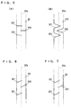
- the connection strips 22 and 24 are respectively formed with curved portions 223 and 243.
- One connection strip 24, representative of these two connection strips 22 and 24, is illustrated in Figure 9.
- This connection strip 24 includes a first portion 24a extending along a side surface of the battery 12 and a second portion 24b along a back surface of the battery 12, wherein the curved portion 243 is formed connecting between the first portion 24a and the second portion 24b.
- the curved portion 243 is formed such that one part in the connection strip 24 projects at its entire width in one direction (outwardly) to form a bend portion.
- connection length between the positive-pole lead 14 or negative-pole lead 16 and the circuit board 20 of the battery 12 is increased by expansion of the layered body or the like, the connection strips 22 and 24 experience tensions in the lengthwise direction. Thereupon the curved portions 223 and 243 are allowed to expand in the lengthwise direction, increasing the length of the connection strips 22, 24 corresponding to the increase in the connection length.
- connection strips 22 and 24 To fix the connection strips 22 and 24 onto the outer surface of the battery 12, there is a necessity to bend them in a manner extending along the outer shape of the battery 12.
- the curved portions 223 and 243 if previously formed at the bend portions of the connection strips 22 and 24 as shown in Figure 8 and Figure 9, facilitate the strips to be bent extending along the outer surface of the battery 12.
- the width-narrowed portion has a decreased strength. Accordingly, the curved portion 223 is readily expanded when a tensile force is applied to the connection strip 22. This reduces loads imparted to other portions than the curved portion 223 of the connection strip 22.
- the width was narrowed at the curved portion 223, it is also possible to reduce the strength of the curved portion 223(243) by reducing the thickness at the curved portion 223(243) of the connection strip 22(24). This also makes the curved portion 223(243) be deformed.
- all the above embodiments can absorb variation in the connection length between the circuit board 20 and the positive-pole lead 14 or the negative-pole lead 16 if partial cuts or cut-outs or curved portions are formed expandable or deformable in at least one of the connection strips 22 and 24. It is therefore possible to relax stresses caused due to the expansion and contraction of the battery 12 (layered body).
- the battery device 10 as embodied has a circuit configuration a shown in Figure 11. That is, this battery device 10 has a function to supply power from the lithium ion battery 12 to a battery-driven device (not shown) through a battery pack terminals.
- the positive pole and the negative pole of the lithium ion battery 12 are connected to the circuit board via the connection strips 22 and 24.
- the circuit board is formed thereon with a protection circuit 18 including a control IC 18a, such as "BA3153FV" made by Rohm Co., Ltd. and a switch 18b.
- the control IC 18a monitors voltage and/or current of the lithium ion battery 12.
- the control IC turns off the switch 18b depending upon the voltage/current when there is an over-current flowing or a voltage drop below a given value. Due to this, the power supply through the battery pack terminals is shut off. Also, the control IC 18a, during electricity charging, turns off the switch 18b based on the voltage/current when a over-current flows or the voltage is increased above a given value. Therefore, the supply of charging power through the battery pack terminal to the lithium ion battery 12 is shut off.
Landscapes
- Engineering & Computer Science (AREA)
- Chemical & Material Sciences (AREA)
- Manufacturing & Machinery (AREA)
- Chemical Kinetics & Catalysis (AREA)
- Electrochemistry (AREA)
- General Chemical & Material Sciences (AREA)
- Microelectronics & Electronic Packaging (AREA)
- Materials Engineering (AREA)
- Connection Of Batteries Or Terminals (AREA)
- Secondary Cells (AREA)
- Battery Mounting, Suspending (AREA)
Abstract
Description


Claims (9)
- A battery device, comprising:a lithium ion battery having a positive pole and a negative pole formed of a polymer material to effect electricity charge and discharge due to lithium ions;a circuit board arranged on an outer surface of said lithium ion battery;a first connection member which connects between said circuit board and said positive pole;a second connection member which connects between said circuit board and said negative pole; anda length varying means provided in association with at least one of said first connection member and said second connection member to vary at least one of a first connection length between said circuit board and said positive pole and a second connection length between said circuit board and said negative pole.
- A battery device according to claim 1, wherein said length varying means includes an expandable/contractible portion formed in at least one of said first connection member and said second connection member.
- A battery device according to claim 2, wherein said expandable/contractible portion includes a readily deformable portion.
- A battery device according to claim 3, wherein at least one of said first connection member and said second connection member is a strip member with a predetermined width, and said readily deformable portion including a plurality of partial cuts each formed extending in a width direction from a lateral end of said strip member.
- A battery device according to claim 4, wherein said plurality of partial cuts extend from said lateral end to a point beyond a widthwise center of said strip member.
- A battery device according to claim 4 or 5, wherein said plurality of partial cuts includes first partial cuts and second partial cuts respectively formed side portions of said strip member.
- A battery device according to claim 6, wherein said first partial cuts and said second partial cuts are alternately formed with respect to a lengthwise direction of said strip member.
- A battery device according to claim 3, wherein said deformable portion includes a curved portion formed in at least one of said first connection member and said second connection member.
- A battery device according to claim 8, wherein at least one of said first connection member and said second connection member includes a bend portion at which bending is given in a manner extending along an outer surface of said lithium ion battery, and said curved portion being formed at said bend portion.
Applications Claiming Priority (3)
| Application Number | Priority Date | Filing Date | Title |
|---|---|---|---|
| JP9041757A JPH10241736A (en) | 1997-02-26 | 1997-02-26 | Battery structure |
| JP4175797 | 1997-02-26 | ||
| PCT/JP1998/000697 WO1998038689A1 (en) | 1997-02-26 | 1998-02-18 | Battery device |
Publications (3)
| Publication Number | Publication Date |
|---|---|
| EP0928037A1 true EP0928037A1 (en) | 1999-07-07 |
| EP0928037A4 EP0928037A4 (en) | 2004-10-13 |
| EP0928037B1 EP0928037B1 (en) | 2007-05-16 |
Family
ID=12617294
Family Applications (1)
| Application Number | Title | Priority Date | Filing Date |
|---|---|---|---|
| EP98904394A Expired - Lifetime EP0928037B1 (en) | 1997-02-26 | 1998-02-18 | Battery device |
Country Status (8)
| Country | Link |
|---|---|
| US (1) | US6117576A (en) |
| EP (1) | EP0928037B1 (en) |
| JP (1) | JPH10241736A (en) |
| KR (1) | KR100511375B1 (en) |
| CN (1) | CN100334773C (en) |
| DE (1) | DE69837782T2 (en) |
| TW (1) | TW364665U (en) |
| WO (1) | WO1998038689A1 (en) |
Cited By (5)
| Publication number | Priority date | Publication date | Assignee | Title |
|---|---|---|---|---|
| EP1035597A1 (en) * | 1999-03-12 | 2000-09-13 | Sony Corporation | Nonaqueous electrolyte battery |
| EP1804328A1 (en) * | 2005-12-29 | 2007-07-04 | Samsung SDI Co., Ltd. | Polymer battery pack |
| EP1808915A1 (en) | 2005-12-29 | 2007-07-18 | Samsung SDI Co., Ltd. | Conductive plate and secondary battery pack using conductive plate |
| EP1093178A4 (en) * | 1999-03-30 | 2007-12-05 | Matsushita Electric Industrial Co Ltd | RECHARGEABLE BATTERY WITH PROTECTION CIRCUIT |
| EP1695401A4 (en) * | 2003-12-16 | 2008-06-04 | Lg Chemical Ltd | DRIVER AND ACCUMULATOR MODULE EQUIPPED WITH SUCH A CONDUCTIVE BODY |
Families Citing this family (23)
| Publication number | Priority date | Publication date | Assignee | Title |
|---|---|---|---|---|
| JP4701464B2 (en) * | 1998-12-04 | 2011-06-15 | 株式会社Gsユアサ | battery |
| JP3899499B2 (en) * | 1998-11-18 | 2007-03-28 | ソニー株式会社 | Non-aqueous electrolyte battery |
| US6337154B1 (en) * | 1999-09-24 | 2002-01-08 | Electrofuel Inc. | Battery box with a metal plastic laminate end |
| JP4494713B2 (en) | 2001-12-04 | 2010-06-30 | パナソニック株式会社 | Battery pack |
| KR100861166B1 (en) | 2002-02-13 | 2008-09-30 | 마츠시타 덴끼 산교 가부시키가이샤 | Manufacturing method of battery pack |
| JP4440548B2 (en) * | 2002-02-13 | 2010-03-24 | パナソニック株式会社 | Battery and manufacturing method thereof |
| KR100958647B1 (en) * | 2002-12-18 | 2010-05-20 | 삼성에스디아이 주식회사 | Pouch Type Secondary Battery Unit |
| KR100645256B1 (en) * | 2004-01-28 | 2006-11-14 | 주식회사 엘지화학 | Secondary battery of assemble-type structure |
| KR100682731B1 (en) * | 2004-02-13 | 2007-02-15 | 주식회사 엘지화학 | Improved battery pack |
| CN1922745B (en) * | 2004-02-18 | 2010-12-01 | 株式会社Lg化学 | Integral cap assembly including protective circuit board and secondary battery including the same |
| US7567306B2 (en) * | 2006-07-14 | 2009-07-28 | Alphamicron, Inc. | Liquid crystal ski goggles and methods of manufacturing the same |
| WO2008021964A2 (en) * | 2006-08-09 | 2008-02-21 | Black & Decker Inc. | Battery pack and internal component arrangement within the battery pack for cordless power tool system |
| KR100770106B1 (en) * | 2006-10-24 | 2007-10-24 | 삼성에스디아이 주식회사 | Lithium secondary battery |
| KR100876266B1 (en) * | 2007-09-28 | 2008-12-26 | 삼성에스디아이 주식회사 | Secondary battery |
| KR100933843B1 (en) | 2008-03-28 | 2009-12-24 | 삼성에스디아이 주식회사 | Lithium secondary battery |
| US10095052B2 (en) | 2010-04-05 | 2018-10-09 | Alphamicron Incorporated | Electronically switchable optical device with a multi-functional optical control apparatus and methods for operating the same |
| EP2556406B1 (en) | 2010-04-05 | 2019-09-18 | Alphamicron Incorporated | Electronically switchable optical device with a multi-functional optical control apparatus and methods for operating the same |
| JP2012099645A (en) * | 2010-11-02 | 2012-05-24 | Mitsubishi Electric Corp | Power storage device |
| US9159984B2 (en) * | 2011-11-25 | 2015-10-13 | Samsung Sdi Co., Ltd. | Rechargeable battery |
| CN106959093B (en) * | 2016-01-08 | 2020-11-03 | 中兴通讯股份有限公司 | A kind of battery deformation detection method and equipment |
| USD837790S1 (en) * | 2016-08-03 | 2019-01-08 | Transcend Information, Inc. | Mobile storage device |
| US12438240B2 (en) | 2019-10-02 | 2025-10-07 | Lg Energy Solution, Ltd. | Cylindrical battery and battery pack including the same |
| KR102580240B1 (en) * | 2019-12-11 | 2023-09-19 | 삼성에스디아이 주식회사 | Battery pack |
Family Cites Families (12)
| Publication number | Priority date | Publication date | Assignee | Title |
|---|---|---|---|---|
| GB2026760B (en) * | 1978-07-27 | 1983-04-27 | Varta Ltd | Battery and a method of its manufacture |
| JPS609300U (en) * | 1983-06-29 | 1985-01-22 | 富士通株式会社 | Chained thin plate parts |
| JPS609300A (en) * | 1983-06-29 | 1985-01-18 | Toshiba Corp | Electrostatic type electroacoustic transducer and its manufacture |
| JPH01177869A (en) * | 1987-12-30 | 1989-07-14 | Tdk Corp | Dc-dc converter |
| JPH01177869U (en) * | 1988-06-03 | 1989-12-19 | ||
| DE68910813T2 (en) * | 1989-06-12 | 1994-06-09 | Honda Motor Co Ltd | Process for the stabilization of electroactive polymer electrodes. |
| CA2093763C (en) * | 1993-04-08 | 1999-12-07 | David Wainwright | Battery incorporating hydraulic activation of disconnect safety device on overcharge |
| JPH07134984A (en) * | 1993-11-10 | 1995-05-23 | Sony Corp | Cylindrical non-aqueous electrolyte secondary battery |
| JPH07220754A (en) * | 1994-02-07 | 1995-08-18 | Tdk Corp | Layer built lithium secondary battery |
| US5538805A (en) * | 1994-05-31 | 1996-07-23 | Power Battery Corporation | Battery with integral recharger |
| US5472804A (en) * | 1994-12-01 | 1995-12-05 | Motorola, Inc. | Battery device with integrated circuit substrate packaging |
| JPH1177864A (en) * | 1997-09-12 | 1999-03-23 | Yokohama Rubber Co Ltd:The | Hose and its manufacture |
-
1997
- 1997-02-26 JP JP9041757A patent/JPH10241736A/en active Pending
-
1998
- 1998-02-18 WO PCT/JP1998/000697 patent/WO1998038689A1/en not_active Ceased
- 1998-02-18 EP EP98904394A patent/EP0928037B1/en not_active Expired - Lifetime
- 1998-02-18 CN CNB988001888A patent/CN100334773C/en not_active Expired - Fee Related
- 1998-02-18 KR KR10-1998-0708542A patent/KR100511375B1/en not_active Expired - Fee Related
- 1998-02-18 DE DE69837782T patent/DE69837782T2/en not_active Expired - Fee Related
- 1998-02-18 US US09/171,746 patent/US6117576A/en not_active Expired - Lifetime
- 1998-02-26 TW TW087202752U patent/TW364665U/en unknown
Cited By (10)
| Publication number | Priority date | Publication date | Assignee | Title |
|---|---|---|---|---|
| EP1035597A1 (en) * | 1999-03-12 | 2000-09-13 | Sony Corporation | Nonaqueous electrolyte battery |
| EP1093178A4 (en) * | 1999-03-30 | 2007-12-05 | Matsushita Electric Industrial Co Ltd | RECHARGEABLE BATTERY WITH PROTECTION CIRCUIT |
| EP1695401A4 (en) * | 2003-12-16 | 2008-06-04 | Lg Chemical Ltd | DRIVER AND ACCUMULATOR MODULE EQUIPPED WITH SUCH A CONDUCTIVE BODY |
| US7615309B2 (en) | 2003-12-16 | 2009-11-10 | Lg Chem, Ltd. | Lead member and secondary battery module with the same |
| EP1804328A1 (en) * | 2005-12-29 | 2007-07-04 | Samsung SDI Co., Ltd. | Polymer battery pack |
| EP1808915A1 (en) | 2005-12-29 | 2007-07-18 | Samsung SDI Co., Ltd. | Conductive plate and secondary battery pack using conductive plate |
| US7879477B2 (en) | 2005-12-29 | 2011-02-01 | Samsung Sdi Co., Ltd. | Polymer battery pack |
| US7887945B2 (en) | 2005-12-29 | 2011-02-15 | Samsung Sdi Co., Ltd. | Conductive plate and secondary battery pack using conductive plate |
| US7993775B2 (en) | 2005-12-29 | 2011-08-09 | Samsung Sdi Co., Ltd. | Conductive plate and secondary battery pack using conductive plate |
| US7993774B2 (en) | 2005-12-29 | 2011-08-09 | Samsung Sdi Co., Ltd. | Conductive plate and secondary battery pack using conductive plate |
Also Published As
| Publication number | Publication date |
|---|---|
| US6117576A (en) | 2000-09-12 |
| JPH10241736A (en) | 1998-09-11 |
| DE69837782D1 (en) | 2007-06-28 |
| WO1998038689A1 (en) | 1998-09-03 |
| EP0928037A4 (en) | 2004-10-13 |
| KR20000065007A (en) | 2000-11-06 |
| TW364665U (en) | 1999-07-11 |
| DE69837782T2 (en) | 2007-10-18 |
| EP0928037B1 (en) | 2007-05-16 |
| KR100511375B1 (en) | 2005-11-21 |
| CN1217825A (en) | 1999-05-26 |
| CN100334773C (en) | 2007-08-29 |
Similar Documents
| Publication | Publication Date | Title |
|---|---|---|
| US6117576A (en) | Battery device | |
| US7585589B2 (en) | Pouch-type lithium secondary battery | |
| KR100779282B1 (en) | Non-aqueous electrolyte secondary battery | |
| US9023513B2 (en) | Rechargeable secondary battery having improved safety against puncture and collapse | |
| US9299970B2 (en) | Jelly-roll type battery unit and winding method thereof and lithium secondary battery comprising the same | |
| CN100517850C (en) | Pouch-type lithium secondary battery and fabrication method thereof | |
| EP0949699A2 (en) | Electrical connection structure in a lithium secondary battery | |
| EP0928035A1 (en) | Prismatic battery with a bow shaped casing | |
| US20060068275A1 (en) | Pouch-type lithium secondary battery and fabrication method thereof | |
| US20120225336A1 (en) | Battery unit and lithium secondary battery employing the same | |
| KR20050121907A (en) | Secondary battery and electrodes assembly using the same | |
| KR101717197B1 (en) | Flexible Battery Employed with a Plurality of Unit Cells | |
| JP4603108B2 (en) | Secondary battery electrode roll | |
| US6258487B1 (en) | Lithium secondary battery including a divided electrode base layer | |
| EP1808915B1 (en) | Conductive plate and secondary battery pack using conductive plate | |
| JP2002050322A (en) | Sealed rectangular flat battery | |
| JP2003187856A (en) | Battery | |
| JP2008166243A (en) | Crude cell for high-capacity secondary battery and its manufacturing method as well as high-capacity secondary battery | |
| KR20240056427A (en) | Elctrode assembly and electrochemical device comprising the same | |
| EP4002576B1 (en) | Power supply assembly and method for manufacturing the same | |
| JP2000285905A (en) | Thin battery | |
| JPH11121040A (en) | Lithium secondary battery | |
| CN116895919A (en) | battery module | |
| JPH11345626A (en) | Sealed battery | |
| JP2003142161A (en) | Flat non-aqueous electrolyte secondary battery |
Legal Events
| Date | Code | Title | Description |
|---|---|---|---|
| PUAI | Public reference made under article 153(3) epc to a published international application that has entered the european phase |
Free format text: ORIGINAL CODE: 0009012 |
|
| 17P | Request for examination filed |
Effective date: 19981016 |
|
| AK | Designated contracting states |
Kind code of ref document: A1 Designated state(s): DE FR GB |
|
| A4 | Supplementary search report drawn up and despatched |
Effective date: 20040830 |
|
| GRAP | Despatch of communication of intention to grant a patent |
Free format text: ORIGINAL CODE: EPIDOSNIGR1 |
|
| GRAC | Information related to communication of intention to grant a patent modified |
Free format text: ORIGINAL CODE: EPIDOSCIGR1 |
|
| GRAS | Grant fee paid |
Free format text: ORIGINAL CODE: EPIDOSNIGR3 |
|
| GRAA | (expected) grant |
Free format text: ORIGINAL CODE: 0009210 |
|
| AK | Designated contracting states |
Kind code of ref document: B1 Designated state(s): DE FR GB |
|
| REG | Reference to a national code |
Ref country code: GB Ref legal event code: FG4D |
|
| REF | Corresponds to: |
Ref document number: 69837782 Country of ref document: DE Date of ref document: 20070628 Kind code of ref document: P |
|
| ET | Fr: translation filed | ||
| PLBE | No opposition filed within time limit |
Free format text: ORIGINAL CODE: 0009261 |
|
| STAA | Information on the status of an ep patent application or granted ep patent |
Free format text: STATUS: NO OPPOSITION FILED WITHIN TIME LIMIT |
|
| 26N | No opposition filed |
Effective date: 20080219 |
|
| PGFP | Annual fee paid to national office [announced via postgrant information from national office to epo] |
Ref country code: DE Payment date: 20090213 Year of fee payment: 12 |
|
| PGFP | Annual fee paid to national office [announced via postgrant information from national office to epo] |
Ref country code: GB Payment date: 20090217 Year of fee payment: 12 |
|
| PGFP | Annual fee paid to national office [announced via postgrant information from national office to epo] |
Ref country code: FR Payment date: 20090213 Year of fee payment: 12 |
|
| GBPC | Gb: european patent ceased through non-payment of renewal fee |
Effective date: 20100218 |
|
| REG | Reference to a national code |
Ref country code: FR Ref legal event code: ST Effective date: 20101029 |
|
| PG25 | Lapsed in a contracting state [announced via postgrant information from national office to epo] |
Ref country code: FR Free format text: LAPSE BECAUSE OF NON-PAYMENT OF DUE FEES Effective date: 20100301 |
|
| PG25 | Lapsed in a contracting state [announced via postgrant information from national office to epo] |
Ref country code: DE Free format text: LAPSE BECAUSE OF NON-PAYMENT OF DUE FEES Effective date: 20100901 |
|
| PG25 | Lapsed in a contracting state [announced via postgrant information from national office to epo] |
Ref country code: GB Free format text: LAPSE BECAUSE OF NON-PAYMENT OF DUE FEES Effective date: 20100218 |