EP0927872A1 - Geschwindigkeits- und Positionsgeber für rotierende Wellen - Google Patents
Geschwindigkeits- und Positionsgeber für rotierende Wellen Download PDFInfo
- Publication number
- EP0927872A1 EP0927872A1 EP98403147A EP98403147A EP0927872A1 EP 0927872 A1 EP0927872 A1 EP 0927872A1 EP 98403147 A EP98403147 A EP 98403147A EP 98403147 A EP98403147 A EP 98403147A EP 0927872 A1 EP0927872 A1 EP 0927872A1
- Authority
- EP
- European Patent Office
- Prior art keywords
- encoder
- sensor
- magnetic
- sensitive elements
- axis
- Prior art date
- Legal status (The legal status is an assumption and is not a legal conclusion. Google has not performed a legal analysis and makes no representation as to the accuracy of the status listed.)
- Granted
Links
- 230000007704 transition Effects 0.000 claims abstract description 69
- 230000010363 phase shift Effects 0.000 claims abstract description 21
- 230000005355 Hall effect Effects 0.000 claims description 4
- 238000000034 method Methods 0.000 claims description 4
- 230000005405 multipole Effects 0.000 abstract description 2
- 238000013461 design Methods 0.000 description 8
- 230000008901 benefit Effects 0.000 description 6
- 238000010276 construction Methods 0.000 description 6
- 238000005259 measurement Methods 0.000 description 4
- 238000005516 engineering process Methods 0.000 description 2
- 230000005415 magnetization Effects 0.000 description 2
- 238000004519 manufacturing process Methods 0.000 description 2
- 238000004377 microelectronic Methods 0.000 description 2
- 241000861223 Issus Species 0.000 description 1
- BGPVFRJUHWVFKM-UHFFFAOYSA-N N1=C2C=CC=CC2=[N+]([O-])C1(CC1)CCC21N=C1C=CC=CC1=[N+]2[O-] Chemical compound N1=C2C=CC=CC2=[N+]([O-])C1(CC1)CCC21N=C1C=CC=CC1=[N+]2[O-] BGPVFRJUHWVFKM-UHFFFAOYSA-N 0.000 description 1
- 229920000297 Rayon Polymers 0.000 description 1
- 239000000470 constituent Substances 0.000 description 1
- 238000012937 correction Methods 0.000 description 1
- 230000001815 facial effect Effects 0.000 description 1
- 239000000463 material Substances 0.000 description 1
- 238000012545 processing Methods 0.000 description 1
- 239000002964 rayon Substances 0.000 description 1
- 238000006467 substitution reaction Methods 0.000 description 1
Images


Classifications
-
- G—PHYSICS
- G01—MEASURING; TESTING
- G01D—MEASURING NOT SPECIALLY ADAPTED FOR A SPECIFIC VARIABLE; ARRANGEMENTS FOR MEASURING TWO OR MORE VARIABLES NOT COVERED IN A SINGLE OTHER SUBCLASS; TARIFF METERING APPARATUS; MEASURING OR TESTING NOT OTHERWISE PROVIDED FOR
- G01D5/00—Mechanical means for transferring the output of a sensing member; Means for converting the output of a sensing member to another variable where the form or nature of the sensing member does not constrain the means for converting; Transducers not specially adapted for a specific variable
- G01D5/12—Mechanical means for transferring the output of a sensing member; Means for converting the output of a sensing member to another variable where the form or nature of the sensing member does not constrain the means for converting; Transducers not specially adapted for a specific variable using electric or magnetic means
- G01D5/14—Mechanical means for transferring the output of a sensing member; Means for converting the output of a sensing member to another variable where the form or nature of the sensing member does not constrain the means for converting; Transducers not specially adapted for a specific variable using electric or magnetic means influencing the magnitude of a current or voltage
- G01D5/142—Mechanical means for transferring the output of a sensing member; Means for converting the output of a sensing member to another variable where the form or nature of the sensing member does not constrain the means for converting; Transducers not specially adapted for a specific variable using electric or magnetic means influencing the magnitude of a current or voltage using Hall-effect devices
- G01D5/145—Mechanical means for transferring the output of a sensing member; Means for converting the output of a sensing member to another variable where the form or nature of the sensing member does not constrain the means for converting; Transducers not specially adapted for a specific variable using electric or magnetic means influencing the magnitude of a current or voltage using Hall-effect devices influenced by the relative movement between the Hall device and magnetic fields
Definitions
- the present invention relates to a device for relative position and speed measurement of a shaft mobile in rotation, composed of a magnetic encoder annular, with multipolar magnetization, integral and concentric of the shaft, and a sensor at least two separate sensitive elements, Hall effect or magnetoristance, linked to a fixed frame.
- the originality of the invention relates more particularly to new designs of multipole encoders which simplify the final assembly of measuring devices and using a type sensor unique against coders with characteristics of different magnetization.
- signals from sensitive elements are shaped sinusoidal, it is also known to be able to adjust quadrature by signal processing suitable electronics.
- a provision consists of mounting concentrically and in solidarity with the rotating shaft, a disc-shaped encoder annular, magnetized on one of its faces.
- the magnetic transitions defined between the sectors of North polarity and the South polarity sectors are generally carried by spokes of the disc or the encoder ring.
- the multipolar magnet is therefore consisting of a number equal to 2m circular sectors or poles of angle ⁇ / m, of alternating polarities opposite, which determine m sector periods of 2 ⁇ / m of angular value.
- the first problem resulting from this provision comes from the fact that with each new conception of a measuring device modifying, i.e. the number of encoder periods, i.e. the position of the sensor on the reading radius R, it is necessary to create a new sensor with two sensitive elements suitably spaced to ensure the condition of squaring, which increases manufacturing costs.
- the appropriate manufacturing technologies are preferably those that implement processes by carrying sensitive elements into discrete components on a support, the placement details of which are insufficient and do not allow to overcome the obligation of an adjustment at the end of assembly of each measuring device built.
- the purpose of the present invention is to overcome these disadvantages by proposing a new device rotation speed and position measurement, which comprises on the one hand a sensor carrying two elements, sensitive to Hall effect or magnetoresistance, to precise predetermined spacing, linked to a fixed frame and on the other hand a multipolar encoder, integral with the rotating part and centered on the axis of rotation, realized in such a way that the sensitive elements of the sensor always have the same relative phase shift in the magnetic field of the encoder, when said sensor is moved along an axis passing through the centers of sensitive elements.
- the invention also relates to the conditions using the same sensor in front of encoders different dimensions or that have a number different from magnetic periods.
- This character universality gives the manufacturer the possibility of realize the sensor in integrated circuit by known micro-electronic technologies, which can possibly, with a view to miniaturization, drive to tighten the elements sensitive to a value less than that which corresponds to the placement in quadrature of the sensor in the magnetic field of the encoder then orthogonalize the signals from sensitive elements by simple electronic means known; the deviation from exact squaring being of value constant, electronic correction remains constant for all coders produced and used in conditions of the invention.
- the invention also relates to several variants of realization of circular multipolar encoders or annulars, including the length of the magnetic period, measured along a previously defined axis, is constant, regardless of the number of periods in the magnetic division per turn of encoder and whatever are the dimensions of said encoder.
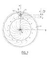
- Figure 1 shows a measuring device comprising a circular encoder of annular shape 1, according to the prior art, comprising m periods North-South magnetic, concentrically united to a rotating shaft not shown facing a sensor 2 comprising two sensitive elements 21 and 22, the centers are distant by a value d.
- the two sensitive elements of the sensor 21 and 22, both located on the same circle C L of reading radius R, are in geometric quadrature in the magnetic field of the encoder if the following relation is verified: d 2R * sin [(2n + 1) * ⁇ / 4m] n being a negative, zero or positive integer.
- the distance d can take at most m distinct values for a given reading radius R.
- any deviation from the values of d and R set by the designer according to this relation entailed deviations from quadrature therefore requires adjustment after assembly of the device.
- the design of a new device comprising an encoder with a number different from magnetic poles usually leads to design also a new sensor with a distance d adapted.
- FIG. 2 represents a measuring device according to the invention, comprising a sensor 5, produced in an integrated circuit by micro-electronic means for example, which has two elements 51 and 52 sensitive to the magnetic field, the distance d between their centers is fixed at a single and constant value and whose position of the axis joining said centers is known. It further comprises a magnetic encoder 4 concentric and integral with the movable shaft in rotation, not shown, and with an axis of rotation ⁇ R.
- the sensor 5 is mounted in a plane P parallel to the magnetized face 6 of the encoder 4, so that the sensitive elements 51 and 52 are opposite the magnetic pattern of the encoder at an air gap distance e.
- the axis ⁇ c of the centers of the sensitive elements belonging to this plane P is located at a distance R 0 from the axis of rotation ⁇ R of the device.
- the axis ⁇ c is the axis on which the magnetic pattern of the encoder 4 is read by each of the sensitive elements 51 and 52.
- the distance d between the centers of the two sensitive elements is chosen to be compatible with the embodiment of the sensor .
- the axis ⁇ c is the axis on which the magnetic pattern of the encoder 4 is read by each of the sensitive elements 51 and 52.
- the spacing d being chosen, the quadrature situation or a phase shift situation of constant value is obtained whatever the position of the sensor holder 8 moving on the axis ⁇ c provided that the sensitive elements 51 and 52 both remain opposite the magnetic pattern of the encoder 4.
- the annular encoder 4 made of one of the constituent materials of the permanent magnets known to those skilled in the art, is magnetized on one of its faces 6, according to a succession in rotationally scrollable North and South magnetic patterns constituting m magnetic periods.
- one of the magnetic transitions separating two poles of opposite polarities is represented by one or the other of the systems of equations in polar coordinates ( ⁇ , ⁇ ): or
- the set of magnetic transitions of the encoder is defined by 2m successive rotations of angle ⁇ / m from the first magnetic transition from the center of the encoder giving 2m transitions or m periods magnetic.
- FIG. 3a represents the layout according to the invention of a magnetic transition 10 between two North and South poles on an encoder 4 with center O.
- the axis ⁇ c located at a distance R o from the center O intersects the axis Oz, over which the distance R o at point X 'is measured.
- the point X ′ of the axis Oz is the origin of the magnetic transition 10 in the form of a spiral, which extends to the outer limit of the encoder.
- a point of the transition 10 is defined by its polar coordinates ( ⁇ , ⁇ ) which are on the one hand the module ⁇ and on the other hand the angle ⁇ of the origin Oz of the phase defined by the following relationships: in which, the quantity a ⁇ is carried by the axis ⁇ c from the origin X ', a is a constant calculated as a function of the distance d between the sensitive centers of the sensor and the number of magnetic periods of the encoder, ⁇ is the angle of rotation in the direct direction around the center O of the encoder 4 which generates, from the point the axis ⁇ c of ordinate a ⁇ , the corresponding point of the transition 10 phase shifted by the angle ⁇ relative to l 'origin.
- FIG. 3b represents the plot according to the invention of a magnetic transition 12 between two North and South poles on an encoder 4 responding to the relationships in polar coordinates ( ⁇ , ⁇ ) as follows: with a rotation of opposite direction of angle - ⁇ of the point of ordinate a ⁇ belonging to the axis ⁇ c , to generate the corresponding point of the transition 12.
- FIG. 4 represents a first embodiment a magnetic encoder according to the invention, for which the layout of all the transitions between the poles magnetic north and south which are obtained by rotations, around the center O of the encoder, of the transition 10 as described in FIG. 3a. Each transition is deduced from the transition immediately consecutive by a rotation of angle ⁇ / m.
- the succession of these transitions 10 defines a succession of 2m North or South poles of the encoder magnet 4.
- the axis ⁇ c of origin X 'located on the axis Oz, at a distance R o from the center O of the encoder 4 intercepts the succession of transitions 10 according to a constant step equal to ⁇ a / m, while the circumferential step is by construction equal to ⁇ / m.
- the sensor 5 is placed so that the centers of the sensitive elements 51 and 52, distant from d, are on the axis ⁇ c .
- the signals from the sensitive elements 51 and 52 remain in constant phase shift, the value of which is solely a function of the relative value of the distance d, chosen as the distance separating the centers sensitive elements of the sensor, at the value of the pitch ⁇ a / m of the encoder measured on the axis ⁇ c .
- This phase shift of the signals from elements 51 and 52 also remains constant when the encoder rotates around its axis O.
- FIG. 5 represents a second embodiment of a magnetic coder according to the invention, for which the plot of all the magnetic transitions between the poles obtained by rotations, around the center O of the coder, of the transition 12 as described in Figure 3b.
- Each transition is deduced from the neighboring transition by a rotation of angle ⁇ / m.
- the succession of these transitions defines a succession of m periods or 2m North or South poles of the encoder magnet.
- FIG. 6 shows that from the plot of FIG. 4, it is possible to produce an infinite number of annular encoders of different diameters and / or width having the advantages described above.
- the two conditions to be fulfilled are firstly that the internal diameter ⁇ i of the chosen encoder is not less than twice the distance R o between the two axes ⁇ c and ⁇ R and secondly that the centers of the sensitive elements of the sensor are located on the axis ⁇ c both facing the encoder.
- the spiral transitions can be extended beyond the layout, necessarily limited, of this figure without losing the advantages of the invention.
- FIG. 7 represents another nonlimiting example of a multipolar coder 4 whose magnetic spiral transitions are defined according to one of the preceding relationships ⁇ and ⁇ , with the distance R o zero.
- the axis ⁇ c on which the centers of the sensitive elements of the sensor are located passes through the center O of the encoder and intercepts the succession of transitions according to a constant step equal to ⁇ a / m, while the circumferential step is by construction equal to ⁇ / m.
- the two sensitive elements 51 and 52, distant from d, from sensor 5 therefore operate in the same situation of signal phase shift as in the previous examples.
- the axis ⁇ c of origin X 'situated on the axis Oz at a distance R o from the center of the encoder 4 passing through the centers of the sensitive elements 51 and 52 and of the sensor 5 intercepts the succession of transitions according to an equal constant pitch at ⁇ b / m ' ⁇ a / m, while the circumferential step is by construction equal to ⁇ / m'.
- the sensor 5 consisting of two sensitive elements 51 and 52 whose centers remote from d are carried by the axis ⁇ c therefore operates in the same situation of phase shift of the signals as for the previous examples, while the number of transitions or the number of magnetic periods of the encoder are different.
- FIGS. 4, 5, 6, 7 and 8 show an essential characteristic of the invention, according to which a single sensor made up of two sensitive elements, whose centers are distant by a value d, makes it possible to construct any sensor device when associated with annular coders whose magnetized face shows an alternation of 2m pale North and South with circumferential scrolling, i.e. m magnetic periods, provided that the transitions between the poles respond, in polar coordinates, to the either of the following systems of equations: or : and that each of the transitions of an encoder is deduced from the immediately consecutive transition by a rotation of angle ⁇ / m relative to the center of the encoder.
- the half-axis ⁇ c of origin X 'corresponding to its intersection in facial projection with the axis Oz which is the origin of the phases, located at a distance R o from the center of the encoder, carries the centers of the two sensitive elements of the sensor in any position opposite the encoder whose internal diameter is at least equal to 2 R o .
- the value of R o which depends on the choice of the designer can take any value from the zero value.
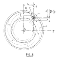
- Figure 9 shows another design of the device measurement where the phase shift of the output signals of sensitive elements 51 and 52 of sensor 5 is different of squaring.
- This choice can be made for example to allow a simplification of the realization of the encoder 4 or greater miniaturization of the sensor 5, by reducing the distance d from the centers of sensitive elements 51 and 52.
- the value of the phase shift chosen can be unified to all designs of speed sensor devices, and then it's possible to also provide a unified treatment of sensor 5 signals and thus maintain the benefit of the existence of a single sensor 5 for all designs of speed sensing devices or position.
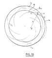
- FIG. 10 represents, for an annular encoder 13 of small width, a possibility of simplification which consists in replacing the magnetic transition between two pale North and South in arc of spiral by a magnetic transition in arc of circle 14 of radius r, centered on the center of curvature O 'of point A of the spiral 15, located at the average diameter ⁇ m of the encoder.
- the means for calculating this radius of curvature and the position of the center of curvature are known.
- Another possibility is to use a circular arc transition 14, in substitution for the spiral transition 15 for its part between the inner circumference C i and the outer circumference C e of the encoder, which consists in choosing the arc of a circle closest to the spiral axis by a method of minimizing the average of the quadratic distances of the two plots.
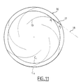
- FIG. 11 represents another simplified embodiment of an annular encoder 16 of small width which consists in replacing the magnetic transition between two North and South poles 19 in a spiral arc by a linear magnetic transition 17.
- the line 18 defining the position of the magnetic transition 17 can be either tangent to the spiral at mid-radius of the encoder 16, or intersecting passing through the two points P 1 and P 2 of intersection of the spiral with the internal circumferences C i and external C e of the coding ring 16.
- the straight line 18 can also be the secant with a spiral arc, the position of which minimizes the mean of the quadratic differences in distance between the spiral and the straight line over the width of the annular magnet.
Landscapes
- Physics & Mathematics (AREA)
- General Physics & Mathematics (AREA)
- Transmission And Conversion Of Sensor Element Output (AREA)
Applications Claiming Priority (2)
| Application Number | Priority Date | Filing Date | Title |
|---|---|---|---|
| FR9716783 | 1997-12-31 | ||
| FR9716783A FR2773212B1 (fr) | 1997-12-31 | 1997-12-31 | Capteurs de position et de vitesse d'un arbre en rotation |
Publications (2)
| Publication Number | Publication Date |
|---|---|
| EP0927872A1 true EP0927872A1 (de) | 1999-07-07 |
| EP0927872B1 EP0927872B1 (de) | 2003-07-02 |
Family
ID=9515366
Family Applications (1)
| Application Number | Title | Priority Date | Filing Date |
|---|---|---|---|
| EP98403147A Expired - Lifetime EP0927872B1 (de) | 1997-12-31 | 1998-12-14 | Geschwindigkeits- und Positionsgeber für rotierende Wellen |
Country Status (5)
| Country | Link |
|---|---|
| US (1) | US6163147A (de) |
| EP (1) | EP0927872B1 (de) |
| JP (1) | JPH11248486A (de) |
| DE (1) | DE69816020T2 (de) |
| FR (1) | FR2773212B1 (de) |
Cited By (4)
| Publication number | Priority date | Publication date | Assignee | Title |
|---|---|---|---|---|
| CN101660892A (zh) * | 2008-08-28 | 2010-03-03 | S.N.R.鲁尔门斯公司 | 用于测量旋转的可移动部件的轴向移动的系统和方法 |
| CN104571116A (zh) * | 2015-01-09 | 2015-04-29 | 西安应用光学研究所 | 一种光电稳定平台的位置回路坐标系转换方法 |
| FR3055959A1 (fr) * | 2016-09-13 | 2018-03-16 | Ntn Snr Roulements | Systeme de determination d’au moins un parametre de rotation d’un organe tournant |
| FR3055960A1 (fr) * | 2016-09-13 | 2018-03-16 | Ntn Snr Roulements | Codeur et systeme de determination d’au moins un parametre de rotation comprenant un tel codeur |
Families Citing this family (21)
| Publication number | Priority date | Publication date | Assignee | Title |
|---|---|---|---|---|
| DE19849613A1 (de) * | 1998-10-28 | 2000-05-04 | Philips Corp Intellectual Pty | Anordnung zur Messung einer relativen linearen Position |
| EP1208348B1 (de) * | 2000-03-08 | 2012-07-18 | Mts Systems Corporation | Linearer und rotierender magnetischer sensor |
| JP2003211765A (ja) | 2001-11-16 | 2003-07-29 | Matsushita Electric Ind Co Ltd | 印字装置及びロール装置 |
| ITTO20030024A1 (it) * | 2003-01-20 | 2004-07-21 | Rft Spa | Dispositivo di comando a ruota fonica |
| US7229746B2 (en) * | 2003-04-02 | 2007-06-12 | Delphi Technologies, Inc. | Printed high strength permanent magnet targets for magnetic sensors |
| DE102005021300B4 (de) * | 2005-05-09 | 2007-08-16 | Vs Sensorik Gmbh | Drehgeber |
| FR2898189B1 (fr) * | 2006-03-02 | 2008-10-17 | Moving Magnet Tech | Capteur de position a direction d'aimantation variable et procede de realisation |
| ITTO20060771A1 (it) * | 2006-10-25 | 2008-04-26 | Elmotron S R L | Dispositivo rilevatore della posizione e della velocita' angolare di un elemento rotante |
| JP2009168679A (ja) * | 2008-01-17 | 2009-07-30 | Denso Corp | 回転検出装置 |
| DE102008043556B4 (de) | 2008-11-07 | 2022-03-31 | Dr. Johannes Heidenhain Gmbh | Positionsmesseinrichtung |
| US10704925B2 (en) * | 2009-01-12 | 2020-07-07 | Infineon Technologies Ag | Sensor and method for determining angular position including measuring magnetic field lines at a distance greater than the inner radius and less than the outer radius of a ring magnet, and at a distance greater than the outer radius or less than the inner radius |
| DE102009023395B4 (de) | 2009-05-29 | 2019-06-19 | Lakeview Innovation Ltd. | Codescheibe für einen Encoder |
| WO2016029972A1 (en) * | 2014-08-29 | 2016-03-03 | Aktiebolaget Skf | Sensor-bearing unit, mechanical system comprising such unit and method for manufacturing such unit |
| DE202014105652U1 (de) * | 2014-11-24 | 2015-06-18 | Infineon Technologies Ag | Magnetanordnung für magnetischen Positionssensor und entsprechende Positionssensoreinrichtung |
| FR3051552B1 (fr) * | 2016-05-18 | 2018-05-25 | Continental Automotive France | Capteur de position inductif lineaire pour une mesure angulaire d'une piece mecanique en rotation |
| JP6798530B2 (ja) * | 2018-02-28 | 2020-12-09 | 株式会社デンソー | リニアポジションセンサ |
| FR3078775B1 (fr) * | 2018-03-12 | 2020-04-03 | Ntn-Snr Roulements | Systeme de determination d'au moins un parametre de rotation d'un organe tournant |
| EP3671222A1 (de) | 2018-12-18 | 2020-06-24 | Baumer Electric AG | Drehgebervorrichtung mit zwei detektoreinheiten auf gemeinsamem träger |
| FR3093798B1 (fr) * | 2019-03-12 | 2021-06-25 | Ntn Snr Roulements | Système de détermination d’au moins un paramètre de rotation d’un organe tournant |
| CN112986608B (zh) * | 2021-03-31 | 2023-04-11 | 长光卫星技术股份有限公司 | 一种基于线性霍尔的微纳卫星反作用飞轮测速方法 |
| EP4675298A3 (de) * | 2024-07-02 | 2026-01-28 | Honeywell International Inc. | Ausseraxialer magnetfeldsensor |
Citations (3)
| Publication number | Priority date | Publication date | Assignee | Title |
|---|---|---|---|---|
| FR2271544A2 (de) * | 1974-05-15 | 1975-12-12 | Siemens Ag | |
| EP0431976A2 (de) * | 1989-12-08 | 1991-06-12 | Hewlett-Packard Company | Vorrichtung und Verfahren fÀ¼r optische Kodierung |
| DE9420147U1 (de) * | 1994-12-16 | 1995-03-02 | Ind Tech Res Inst | Flacher magnetischer Meßgeber für eine absolute Position eines sich drehenden Teiles |
-
1997
- 1997-12-31 FR FR9716783A patent/FR2773212B1/fr not_active Expired - Fee Related
-
1998
- 1998-12-14 DE DE69816020T patent/DE69816020T2/de not_active Expired - Fee Related
- 1998-12-14 EP EP98403147A patent/EP0927872B1/de not_active Expired - Lifetime
- 1998-12-30 US US09/223,484 patent/US6163147A/en not_active Expired - Lifetime
-
1999
- 1999-01-04 JP JP11000177A patent/JPH11248486A/ja not_active Withdrawn
Patent Citations (3)
| Publication number | Priority date | Publication date | Assignee | Title |
|---|---|---|---|---|
| FR2271544A2 (de) * | 1974-05-15 | 1975-12-12 | Siemens Ag | |
| EP0431976A2 (de) * | 1989-12-08 | 1991-06-12 | Hewlett-Packard Company | Vorrichtung und Verfahren fÀ¼r optische Kodierung |
| DE9420147U1 (de) * | 1994-12-16 | 1995-03-02 | Ind Tech Res Inst | Flacher magnetischer Meßgeber für eine absolute Position eines sich drehenden Teiles |
Cited By (13)
| Publication number | Priority date | Publication date | Assignee | Title |
|---|---|---|---|---|
| CN101660892A (zh) * | 2008-08-28 | 2010-03-03 | S.N.R.鲁尔门斯公司 | 用于测量旋转的可移动部件的轴向移动的系统和方法 |
| CN103217179A (zh) * | 2008-08-28 | 2013-07-24 | S.N.R.鲁尔门斯公司 | 用于测量旋转的可移动部件的轴向移动的方法 |
| CN101660892B (zh) * | 2008-08-28 | 2015-07-22 | S.N.R.鲁尔门斯公司 | 用于测量旋转的可移动部件的轴向移动的系统和方法 |
| CN103217179B (zh) * | 2008-08-28 | 2015-08-26 | S.N.R.鲁尔门斯公司 | 用于测量旋转的可移动部件的轴向移动的方法 |
| CN104571116A (zh) * | 2015-01-09 | 2015-04-29 | 西安应用光学研究所 | 一种光电稳定平台的位置回路坐标系转换方法 |
| CN104571116B (zh) * | 2015-01-09 | 2017-02-22 | 西安应用光学研究所 | 一种光电稳定平台的位置回路坐标系转换方法 |
| FR3055959A1 (fr) * | 2016-09-13 | 2018-03-16 | Ntn Snr Roulements | Systeme de determination d’au moins un parametre de rotation d’un organe tournant |
| FR3055960A1 (fr) * | 2016-09-13 | 2018-03-16 | Ntn Snr Roulements | Codeur et systeme de determination d’au moins un parametre de rotation comprenant un tel codeur |
| WO2018051011A1 (fr) * | 2016-09-13 | 2018-03-22 | Ntn-Snr Roulements | Système de détermination d'au moins un paramètre de rotation d'un organe tournant |
| CN110023720A (zh) * | 2016-09-13 | 2019-07-16 | Ntn-Snr轴承股份有限公司 | 确定转动构件的至少一转动参数的确定系统 |
| US20190265073A1 (en) * | 2016-09-13 | 2019-08-29 | Ntn-Snr Roulements | System for determining at least one rotation parameter of a rotating member |
| US10969252B2 (en) * | 2016-09-13 | 2021-04-06 | Ntn-Snr Roulements | System for determining at least one rotation parameter of a rotating member |
| CN110023720B (zh) * | 2016-09-13 | 2021-12-14 | Ntn-Snr轴承股份有限公司 | 确定转动构件的至少一转动参数的确定系统 |
Also Published As
| Publication number | Publication date |
|---|---|
| US6163147A (en) | 2000-12-19 |
| FR2773212A1 (fr) | 1999-07-02 |
| FR2773212B1 (fr) | 2000-03-31 |
| EP0927872B1 (de) | 2003-07-02 |
| DE69816020T2 (de) | 2004-06-03 |
| DE69816020D1 (de) | 2003-08-07 |
| JPH11248486A (ja) | 1999-09-17 |
Similar Documents
| Publication | Publication Date | Title |
|---|---|---|
| EP0927872B1 (de) | Geschwindigkeits- und Positionsgeber für rotierende Wellen | |
| EP1949036B1 (de) | Magnetischer winkelpositionssensor für eine umdrehung bis 360° | |
| EP1017967B1 (de) | Digitaler geber zur messung einer relativen position | |
| EP2496914B1 (de) | Bidirektionaler magnetischer positionssensor mit rotierendem magnetfeld | |
| EP2452160B1 (de) | Multiperiodischer absoluter positionssensor | |
| EP1403622B1 (de) | Absoluter Drehgeber | |
| WO2008071875A2 (fr) | Capteur de position lineaire ou rotatif a profil d'aimant variable | |
| WO2007099238A1 (fr) | Capteur de position a direction d'aimantation variable et procede de realisation | |
| WO2010046550A1 (fr) | Capteur de position magnetique a mesure de direction de champ et a collecteur de flux | |
| EP1102995B1 (de) | Wälzlager mit vorrichtung zur messdatenerfassung | |
| EP0939293B1 (de) | Mehrpoliger magnetischer Ring | |
| EP0319355A2 (de) | Lager mit Magnetfelddetektor | |
| WO2016169645A1 (fr) | Capteur de mesure du couple d'un arbre d'entrainement | |
| EP1404016B1 (de) | Vorrichtung zur Steuerung eines elektronischen kommutierten Motor mit winkelverteilten Singularitäten | |
| EP0443937B1 (de) | Geschwindigkeitsmessaufnehmer für den Ausgang eines Getriebes | |
| FR2833663A1 (fr) | Roulement comprenant un ensemble de transmission d'informations sans fil | |
| EP3807598B1 (de) | Verfahren zur bestimmung einer relativen winkellage zwischen zwei teilen | |
| EP0038744A1 (de) | Schrittmotor, besonders für eine elektronische Uhr | |
| EP4305385A1 (de) | Magnetsensor und ferromagnetische pole | |
| EP3708963A1 (de) | System zur bestimmung mindestens eines parameters der rotation eines rotationsorgans | |
| EP4235109B1 (de) | Prüfkörper mit kodierer | |
| EP3708964B1 (de) | System zur bestimmung mindestens eines parameters der rotation eines rotationsorgans | |
| FR3058202B1 (fr) | Robinet pour reservoir de fluide et bouteille comprenant un tel robinet | |
| FR2644240A1 (fr) | Capteur inductif de position angulaire | |
| WO1991006108A1 (fr) | Actionneur electromagnetique monophase |
Legal Events
| Date | Code | Title | Description |
|---|---|---|---|
| PUAI | Public reference made under article 153(3) epc to a published international application that has entered the european phase |
Free format text: ORIGINAL CODE: 0009012 |
|
| AK | Designated contracting states |
Kind code of ref document: A1 Designated state(s): DE ES FR IT |
|
| AX | Request for extension of the european patent |
Free format text: AL;LT;LV;MK;RO;SI |
|
| 17P | Request for examination filed |
Effective date: 19990913 |
|
| AKX | Designation fees paid |
Free format text: DE ES FR GB |
|
| RBV | Designated contracting states (corrected) |
Designated state(s): DE ES FR IT |
|
| GRAH | Despatch of communication of intention to grant a patent |
Free format text: ORIGINAL CODE: EPIDOS IGRA |
|
| GRAH | Despatch of communication of intention to grant a patent |
Free format text: ORIGINAL CODE: EPIDOS IGRA |
|
| GRAA | (expected) grant |
Free format text: ORIGINAL CODE: 0009210 |
|
| AK | Designated contracting states |
Designated state(s): DE ES FR IT |
|
| PG25 | Lapsed in a contracting state [announced via postgrant information from national office to epo] |
Ref country code: ES Free format text: LAPSE BECAUSE OF FAILURE TO SUBMIT A TRANSLATION OF THE DESCRIPTION OR TO PAY THE FEE WITHIN THE PRESCRIBED TIME-LIMIT Effective date: 20030702 |
|
| REF | Corresponds to: |
Ref document number: 69816020 Country of ref document: DE Date of ref document: 20030807 Kind code of ref document: P |
|
| PLBE | No opposition filed within time limit |
Free format text: ORIGINAL CODE: 0009261 |
|
| STAA | Information on the status of an ep patent application or granted ep patent |
Free format text: STATUS: NO OPPOSITION FILED WITHIN TIME LIMIT |
|
| 26N | No opposition filed |
Effective date: 20040405 |
|
| PGFP | Annual fee paid to national office [announced via postgrant information from national office to epo] |
Ref country code: IT Payment date: 20071221 Year of fee payment: 10 |
|
| PGFP | Annual fee paid to national office [announced via postgrant information from national office to epo] |
Ref country code: DE Payment date: 20071221 Year of fee payment: 10 |
|
| PGFP | Annual fee paid to national office [announced via postgrant information from national office to epo] |
Ref country code: FR Payment date: 20071217 Year of fee payment: 10 |
|
| REG | Reference to a national code |
Ref country code: FR Ref legal event code: ST Effective date: 20090831 |
|
| PG25 | Lapsed in a contracting state [announced via postgrant information from national office to epo] |
Ref country code: DE Free format text: LAPSE BECAUSE OF NON-PAYMENT OF DUE FEES Effective date: 20090701 |
|
| PG25 | Lapsed in a contracting state [announced via postgrant information from national office to epo] |
Ref country code: FR Free format text: LAPSE BECAUSE OF NON-PAYMENT OF DUE FEES Effective date: 20081231 |
|
| PG25 | Lapsed in a contracting state [announced via postgrant information from national office to epo] |
Ref country code: IT Free format text: LAPSE BECAUSE OF NON-PAYMENT OF DUE FEES Effective date: 20081214 |