EP3708964B1 - System zur bestimmung mindestens eines parameters der rotation eines rotationsorgans - Google Patents
System zur bestimmung mindestens eines parameters der rotation eines rotationsorgans Download PDFInfo
- Publication number
- EP3708964B1 EP3708964B1 EP20162813.8A EP20162813A EP3708964B1 EP 3708964 B1 EP3708964 B1 EP 3708964B1 EP 20162813 A EP20162813 A EP 20162813A EP 3708964 B1 EP3708964 B1 EP 3708964B1
- Authority
- EP
- European Patent Office
- Prior art keywords
- magnetic
- transitions
- distance
- magnetic field
- track
- Prior art date
- Legal status (The legal status is an assumption and is not a legal conclusion. Google has not performed a legal analysis and makes no representation as to the accuracy of the status listed.)
- Active
Links
Images

Classifications
-
- G—PHYSICS
- G01—MEASURING; TESTING
- G01R—MEASURING ELECTRIC VARIABLES; MEASURING MAGNETIC VARIABLES
- G01R33/00—Arrangements or instruments for measuring magnetic variables
- G01R33/02—Measuring direction or magnitude of magnetic fields or magnetic flux
- G01R33/06—Measuring direction or magnitude of magnetic fields or magnetic flux using galvano-magnetic devices
- G01R33/07—Hall effect devices
-
- G—PHYSICS
- G01—MEASURING; TESTING
- G01D—MEASURING NOT SPECIALLY ADAPTED FOR A SPECIFIC VARIABLE; ARRANGEMENTS FOR MEASURING TWO OR MORE VARIABLES NOT COVERED IN A SINGLE OTHER SUBCLASS; TARIFF METERING APPARATUS; MEASURING OR TESTING NOT OTHERWISE PROVIDED FOR
- G01D5/00—Mechanical means for transferring the output of a sensing member; Means for converting the output of a sensing member to another variable where the form or nature of the sensing member does not constrain the means for converting; Transducers not specially adapted for a specific variable
- G01D5/12—Mechanical means for transferring the output of a sensing member; Means for converting the output of a sensing member to another variable where the form or nature of the sensing member does not constrain the means for converting; Transducers not specially adapted for a specific variable using electric or magnetic means
- G01D5/14—Mechanical means for transferring the output of a sensing member; Means for converting the output of a sensing member to another variable where the form or nature of the sensing member does not constrain the means for converting; Transducers not specially adapted for a specific variable using electric or magnetic means influencing the magnitude of a current or voltage
- G01D5/142—Mechanical means for transferring the output of a sensing member; Means for converting the output of a sensing member to another variable where the form or nature of the sensing member does not constrain the means for converting; Transducers not specially adapted for a specific variable using electric or magnetic means influencing the magnitude of a current or voltage using Hall-effect devices
- G01D5/145—Mechanical means for transferring the output of a sensing member; Means for converting the output of a sensing member to another variable where the form or nature of the sensing member does not constrain the means for converting; Transducers not specially adapted for a specific variable using electric or magnetic means influencing the magnitude of a current or voltage using Hall-effect devices influenced by the relative movement between the Hall device and magnetic fields
-
- G—PHYSICS
- G01—MEASURING; TESTING
- G01R—MEASURING ELECTRIC VARIABLES; MEASURING MAGNETIC VARIABLES
- G01R33/00—Arrangements or instruments for measuring magnetic variables
- G01R33/02—Measuring direction or magnitude of magnetic fields or magnetic flux
- G01R33/06—Measuring direction or magnitude of magnetic fields or magnetic flux using galvano-magnetic devices
- G01R33/09—Magnetoresistive devices
- G01R33/091—Constructional adaptation of the sensor to specific applications
-
- G—PHYSICS
- G01—MEASURING; TESTING
- G01D—MEASURING NOT SPECIALLY ADAPTED FOR A SPECIFIC VARIABLE; ARRANGEMENTS FOR MEASURING TWO OR MORE VARIABLES NOT COVERED IN A SINGLE OTHER SUBCLASS; TARIFF METERING APPARATUS; MEASURING OR TESTING NOT OTHERWISE PROVIDED FOR
- G01D5/00—Mechanical means for transferring the output of a sensing member; Means for converting the output of a sensing member to another variable where the form or nature of the sensing member does not constrain the means for converting; Transducers not specially adapted for a specific variable
- G01D5/12—Mechanical means for transferring the output of a sensing member; Means for converting the output of a sensing member to another variable where the form or nature of the sensing member does not constrain the means for converting; Transducers not specially adapted for a specific variable using electric or magnetic means
- G01D5/244—Mechanical means for transferring the output of a sensing member; Means for converting the output of a sensing member to another variable where the form or nature of the sensing member does not constrain the means for converting; Transducers not specially adapted for a specific variable using electric or magnetic means influencing characteristics of pulses or pulse trains; generating pulses or pulse trains
- G01D5/245—Mechanical means for transferring the output of a sensing member; Means for converting the output of a sensing member to another variable where the form or nature of the sensing member does not constrain the means for converting; Transducers not specially adapted for a specific variable using electric or magnetic means influencing characteristics of pulses or pulse trains; generating pulses or pulse trains using a variable number of pulses in a train
- G01D5/2451—Incremental encoders
-
- G—PHYSICS
- G01—MEASURING; TESTING
- G01R—MEASURING ELECTRIC VARIABLES; MEASURING MAGNETIC VARIABLES
- G01R33/00—Arrangements or instruments for measuring magnetic variables
- G01R33/02—Measuring direction or magnitude of magnetic fields or magnetic flux
- G01R33/06—Measuring direction or magnitude of magnetic fields or magnetic flux using galvano-magnetic devices
- G01R33/09—Magnetoresistive devices
- G01R33/093—Magnetoresistive devices using multilayer structures, e.g. giant magnetoresistance sensors
-
- G—PHYSICS
- G01—MEASURING; TESTING
- G01R—MEASURING ELECTRIC VARIABLES; MEASURING MAGNETIC VARIABLES
- G01R33/00—Arrangements or instruments for measuring magnetic variables
- G01R33/02—Measuring direction or magnitude of magnetic fields or magnetic flux
- G01R33/06—Measuring direction or magnitude of magnetic fields or magnetic flux using galvano-magnetic devices
- G01R33/09—Magnetoresistive devices
- G01R33/096—Magnetoresistive devices anisotropic magnetoresistance sensors
-
- G—PHYSICS
- G01—MEASURING; TESTING
- G01R—MEASURING ELECTRIC VARIABLES; MEASURING MAGNETIC VARIABLES
- G01R33/00—Arrangements or instruments for measuring magnetic variables
- G01R33/02—Measuring direction or magnitude of magnetic fields or magnetic flux
- G01R33/06—Measuring direction or magnitude of magnetic fields or magnetic flux using galvano-magnetic devices
- G01R33/09—Magnetoresistive devices
- G01R33/098—Magnetoresistive devices comprising tunnel junctions, e.g. tunnel magnetoresistance sensors
-
- G—PHYSICS
- G01—MEASURING; TESTING
- G01D—MEASURING NOT SPECIALLY ADAPTED FOR A SPECIFIC VARIABLE; ARRANGEMENTS FOR MEASURING TWO OR MORE VARIABLES NOT COVERED IN A SINGLE OTHER SUBCLASS; TARIFF METERING APPARATUS; MEASURING OR TESTING NOT OTHERWISE PROVIDED FOR
- G01D5/00—Mechanical means for transferring the output of a sensing member; Means for converting the output of a sensing member to another variable where the form or nature of the sensing member does not constrain the means for converting; Transducers not specially adapted for a specific variable
- G01D5/12—Mechanical means for transferring the output of a sensing member; Means for converting the output of a sensing member to another variable where the form or nature of the sensing member does not constrain the means for converting; Transducers not specially adapted for a specific variable using electric or magnetic means
- G01D5/244—Mechanical means for transferring the output of a sensing member; Means for converting the output of a sensing member to another variable where the form or nature of the sensing member does not constrain the means for converting; Transducers not specially adapted for a specific variable using electric or magnetic means influencing characteristics of pulses or pulse trains; generating pulses or pulse trains
- G01D5/24428—Error prevention
- G01D5/24433—Error prevention by mechanical means
- G01D5/24438—Special design of the sensing element or scale
Definitions
- the invention relates to a system for determining at least one rotation parameter of a rotating member, said system comprising an encoder emitting a periodic magnetic field as well as a sensor capable of detecting said magnetic field.
- At least one rotation parameter of a rotating member such as its position, its speed, its acceleration or its direction of movement.
- each sensitive element can comprise at least one pattern based on a tunnel magnetoresistive material (TMR in English for Tunnel Magneto Resistance) whose resistance varies as a function of the detected magnetic field, as for example described in the document WO-2004/083881 .
- TMR tunnel magnetoresistive material
- the document WO-2006/064169 provides a combination of signals representative of the resistance of each of the sensitive elements in order to deliver two signals in quadrature and of the same amplitude which can be used to calculate said parameter.
- the document WO-2018/051011 proposes a determination system in which the encoder track presents an alternation of North and South magnetic poles separated by transitions each extending following an Archimedean spiral.
- this realization makes it possible to dissociate the number of magnetic poles, the width of these and the diameter of the encoder. It is thus possible to have few poles while keeping magnetic signals of good sinusoidality.
- encoders comprising a body having a cylindrical periphery on which the magnetic track is formed, said track having magnetic transitions aligned with the axis of rotation.
- the width of the poles is the ratio of the circumference to the number of poles, which poses a problem with encoders with a low number of pairs of poles, typically less than 6, since the polar width becomes important, in particular from l of the order of ten millimeters.
- the invention aims to improve the prior art by proposing in particular a system for determining with radial reading of the magnetic field delivered by an encoder, in which the compromise between the periodicity and the amplitude of the detected magnetic field can be satisfied without inducing constraint.
- specific size for the encoder particularly in relation to a magnetic encoder with a low number of pole pairs.
- the radial reading encoder according to the invention is such that the polar width of each of the poles is independent of the number of pairs of poles, thus being able to reconcile a small number of pairs of poles with adequate positioning of the sensitive elements relative to the sinusoidality and the amplitude of the magnetic field to be detected.
- the invention proposes a system for determining at least one rotation parameter of a rotating member according to claim 1.
- a system for determining at least one rotation parameter of a rotating member relative to a fixed structure.
- the parameter of the rotating member can be chosen from its position, its speed, its direction of rotation, its acceleration or its direction of movement, in particular axial.
- the system can be used in connection with the control of a brushless direct current electric motor, making it possible in particular to know the absolute angular position on a pair of motor poles of the rotor relative to the stator.
- the determination system comprises an encoder 1 intended to be integral with the rotating member so as to move jointly with it, said encoder comprising a body having a cylindrical periphery of radius a around an axis of revolution a magnetic track 2 which is capable of emitting a periodic magnetic field representative of the rotation of said encoder.
- the emitted magnetic field can be sinusoidal or pseudo-sinusoidal, that is to say having at least one portion which can be correctly approximated by a sinusoid.
- Track 2 has an alternation of North 2n and South 2s magnetic poles of width l which are separated by transitions 3, each of said transitions extending along a helix of pitch p and angle a.
- the periodic magnetic field delivered by the magnetic track 2 rotates in a plane perpendicular to said magnetic track and to the transitions 3.
- the magnetic field generated by the encoder 1 on a pair of magnetic poles 2n, 2s is the combination of a fundamental, perfect sinusoidal component that we wish to measure to determine the parameter, and several harmonics of odd rank (3, 5 , etc).
- the amplitude H 3 of the harmonic of order 3 can typically represent 5% of the amplitude H 1 of the fundamental. Depending on the position of the sensor and the reading distance, this proportion of the amplitude H 3 of the third harmonic can be much higher.
- the encoder 1 comprises four pairs of poles 2n, 2s, which is particularly suitable for controlling an electric motor with four pairs of poles, the system providing the absolute position on a pair of motor poles, i.e. 90° mechanical.
- the encoder 1 is formed of a magnet on the cylindrical periphery of which the multipolar magnetic track 2 is produced.
- the magnet can be formed from an annular matrix, for example made from a plastic or elastomeric material, in which magnetic particles, in particular ferrite or rare earth particles such as NdFeB, are dispersed.
- the determination system comprises at least one sensor which is intended to be integral with the fixed structure, said sensor being capable of detecting the rotating magnetic field emitted by the encoder 1.
- the sensor comprises a mounting 4 of at least two magnetic sensitive elements 5, said assembly being arranged at a radial reading distance from the magnetic track 2 to deliver quadrature signals which are representative of the rotation of the encoder 1.
- Each of the sensitive elements 5 can in particular be chosen from among the magnetosensitive probes.
- probes based on the Hall effect tunneling magnetoresistors (TMR), anisotropic magnetoresistors (AMR) or giant magnetoresistors (GMR) can measure each of the two components of the magnetic field (normal and tangential to the encoder 1 ).
- TMR tunneling magnetoresistors
- AMR anisotropic magnetoresistors
- GMR giant magnetoresistors
- each element 5 forms a tunnel junction by comprising a stack of a magnetic reference layer, an insulating separation layer and a magnetic layer sensitive to the field to be detected, the resistance of the stack being a function of the relative orientation of the magnetization of the magnetic layers.
- each sensitive element 5 can comprise at least one pattern based on a magnetoresistive material, in particular with tunnel effect, whose resistance varies as a function of the magnetic field, a sensitive element 5 can comprise a single pattern or a group of patterns connected in series or parallel.
- the signals delivered by the assembly 4 of sensitive elements 5 must preferably be in quadrature, that is to say geometrically phase shifted by 90° divided by N pp .
- quadrature signals in the sensor or in an associated calculator, it is known to determine the angular position of the encoder 1, for example by direct calculation of a function arctangent, using a “Look-Up Table” (LUT) or using a CORDIC type method.
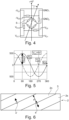
- the assembly 4 can comprise two Wheatstone bridge circuits of four sensitive elements 5, said circuits being arranged in a plane perpendicular to the magnetic track 2 so as to detect the magnetic field rotating in said plane which is emitted by said track.
- Figure 3 represents an assembly 4 in the middle position of the periphery of the encoder 1 to be kept as far away as possible from the edges of said encoder.
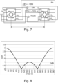
- the determination system comprises according to the invention two sensors whose assemblies 4, 4' are spaced by a distance e measured along the normal N at transitions 3 by respectively delivering signals V 01 , V 02 and V' 01 , V' 02 in quadrature, said system further comprising a signal subtraction device to form SIN, COS signals in quadrature.
- V 1 t G . H 1 . sin ⁇ t + ⁇ 1 + G . H 3 . sin 3 ⁇ t + 3 ⁇ 1 + G . H 5 . sin 5 ⁇ t + 5 ⁇ 1 + ...
- V 2 t G . H 1 . sin ⁇ t + ⁇ 2 + G . H 3 . sin 3 ⁇ t + 3 ⁇ 2 + G . H 5 . sin 5 ⁇ t + 5 ⁇ 2 + ...
- V 1 t ⁇ V 2 t 2 . G . H 1 cos ⁇ t + ⁇ 1 + ⁇ 2 2 ⁇ 2 . G . H 3 . cos 3 ⁇ t + 3 . ⁇ 1 + ⁇ 2 2 + 2 . G . H 5 . cos 5 ⁇ t + 5 . ⁇ 1 + ⁇ 2 2 + ...
- FIG. 8 illustrates the filtering of the third-order harmonic as a function of the value of the phase shift ⁇ 1 - ⁇ 2 .
- V 1 t ⁇ V 2 t 3 .
- G . H 1 cos ⁇ t + ⁇ 1 + ⁇ 2 2 + 0 ⁇ 3 .
- G . H 5 . cos 5 ⁇ t + 5 . ⁇ 1 + ⁇ 2 2 + ⁇
- harmonic 3 is canceled, the fundamental and harmonic 5 have a gain of 1.73 after the subtraction operation.
- the assemblies 4, 4' must therefore be spaced by a distance e measured along the normal N at transitions 3 which is such that: 0.55 L p ⁇ e ⁇ 0.82 L p , module 2 L p ; Or 1.18 L p ⁇ e ⁇ 1.45 L p , module 2 L p .
- the distance e between the assemblies 4, 4' can vary within the ranges mentioned above to optimize the filtering - gain couple.
- the assemblies 4, 4' can be aligned along the normal N at transitions 3, along the axis X or offset circumferentially ( Figure 6 ).
Landscapes
- Physics & Mathematics (AREA)
- General Physics & Mathematics (AREA)
- Condensed Matter Physics & Semiconductors (AREA)
- Transmission And Conversion Of Sensor Element Output (AREA)
Claims (6)
- Bestimmungssystem für mindestens einen Rotationsparameter eines rotierenden Elements, wobei das System Folgendes umfasst:- einen Codierer (1), der dazu bestimmt ist, drehbar mit dem rotierenden Element verbunden zu sein, so dass er sich gemeinsam mit ihm bewegt, wobei der Codierer einen Körper umfasst, der einen zylindrischen Umfang mit einem Radius um eine Drehachse (X) aufweist, wobei der Umfang einen Wechsel von magnetischen Nord- (2n) und Südpolen (2s) mit der Breite I aufweist, die durch Übergänge (3) voneinander getrennt sind, wobei sich jeder der Übergänge entlang einer Helix mit der Steigung p und dem Winkel α erstreckt, um eine multipolare Magnetspur (2) zu bilden, die ein periodisches Magnetfeld aussenden kann, das in einer Ebene senkrecht zur Magnetspur und zu den Übergängen rotiert, wobei die Spur Npp Paare von Nord- (2n) und Südpolen (2s) und eine Polarbreite Lp aufweist, die entlang einer Normalen (N) zu den Übergängen (3) gemessen wird, welche wie folgt sind:wobei das System dadurch gekennzeichnet ist, dass es zwei Sensoren umfasst, die dazu ausgelegt sind, das rotierende Magnetfeld, das vom Codierer mittels einer Anordnung (4, 4') von mindestens zwei empfindlichen magnetischen Elementen (5) für jeden Sensor zu erfassen, wobei die Anordnungen in einem radialen Leseabstand von der Magnetspur (2) angeordnet sind und jede Anordnung (4, 4') dazu angeordnet ist, Quadratursignale (V01, V02; V'01, V'02) zu liefern, und dadurch, dass die Anordnungen (4, 4') der beiden Sensoren um einen Abstand e, der entlang der Normalen (N) zu den Übergangen (3) gemessen wird, voneinander beabstandet sind, und dadurch, dass das System ferner eine Vorrichtung zur Subtraktion zwischen den Signalen der beiden Anordnungen der beiden Sensoren umfasst, um die Quadratursignale (SIN, COS) zu bilden.

- Bestimmungssystem nach Anspruch 1, dadurch gekennzeichnet, dass die Anordnung (4, 4') zwei Wheatstone-Brückenschaltungen mit vier empfindlichen Elementen (5) umfasst, wobei die Schaltungen in einer Ebene senkrecht zur Magnetspur (2) angeordnet sind, um das in der Ebene rotierende Magnetfeld zu erfassen, das von der Spur ausgesendet wird.
- Bestimmungssystem nach einem der Ansprüche 1 oder 2, dadurch gekennzeichnet, dass jedes empfindliche Element (5) mindestens ein Muster auf der Basis eines magnetoresistiven Tunnelmaterials umfasst, dessen Widerstand entsprechend dem erfassten Magnetfeld variiert.
- Bestimmungssystem nach einem der Ansprüche 1 bis 3, dadurch gekennzeichnet, dass der Abstand e wie folgt ist:

- Bestimmungssystem nach einem der Ansprüche 1 bis 4, dadurch gekennzeichnet, dass der Abstand e wie folgt ist:


- Bestimmungssystem nach Anspruch 5, dadurch gekennzeichnet, dass der Abstand e im Wesentlichen gleich 2/3Lp oder 4/3Lp Modulo 2Lp ist.
Applications Claiming Priority (1)
| Application Number | Priority Date | Filing Date | Title |
|---|---|---|---|
| FR1902523A FR3093799B1 (fr) | 2019-03-12 | 2019-03-12 | Système de détermination d’au moins un paramètre de rotation d’un organe tournant |
Publications (2)
| Publication Number | Publication Date |
|---|---|
| EP3708964A1 EP3708964A1 (de) | 2020-09-16 |
| EP3708964B1 true EP3708964B1 (de) | 2024-07-24 |
Family
ID=67514789
Family Applications (1)
| Application Number | Title | Priority Date | Filing Date |
|---|---|---|---|
| EP20162813.8A Active EP3708964B1 (de) | 2019-03-12 | 2020-03-12 | System zur bestimmung mindestens eines parameters der rotation eines rotationsorgans |
Country Status (5)
| Country | Link |
|---|---|
| US (2) | US11598825B2 (de) |
| EP (1) | EP3708964B1 (de) |
| JP (1) | JP7721255B2 (de) |
| CN (1) | CN111693909B (de) |
| FR (1) | FR3093799B1 (de) |
Family Cites Families (15)
| Publication number | Priority date | Publication date | Assignee | Title |
|---|---|---|---|---|
| JPH02307011A (ja) * | 1989-05-23 | 1990-12-20 | Hitachi Ltd | 磁気センサ用回転体及びこれを備える回転検出装置 |
| AT4639U1 (de) * | 2000-10-23 | 2001-09-25 | Austria Mikrosysteme Int | Winkelmesseinrichtung |
| JP2003097971A (ja) * | 2001-09-27 | 2003-04-03 | Koyo Seiko Co Ltd | 転がり軸受およびパルサリング |
| FR2852400B1 (fr) | 2003-03-14 | 2005-06-24 | Capteur magnetoresistif comprenant un element sensible ferromagnetique/antiferromagnetique | |
| FR2879737B1 (fr) | 2004-12-17 | 2007-03-09 | Snr Roulements Sa | Capteur de position a boucle de courant et roulement equipe d'un tel capteur |
| FR2935485B1 (fr) * | 2008-08-28 | 2010-09-10 | Roulements Soc Nouvelle | Systeme et procede de mesure du mouvement axial d'une piece mobile en rotation |
| FR2935478B1 (fr) * | 2008-08-28 | 2010-09-10 | Roulements Soc Nouvelle | Systeme et procede de mesure du mouvement axial d'une piece mobile en rotation |
| US8203334B2 (en) * | 2010-10-28 | 2012-06-19 | General Electric Company | Magnetically spirally encoded shaft for measuring rotational angel, rotational speed and torque |
| JP5762567B2 (ja) | 2011-12-20 | 2015-08-12 | 三菱電機株式会社 | 回転角度検出装置 |
| JP6074988B2 (ja) | 2012-09-28 | 2017-02-08 | アイシン精機株式会社 | 回転磁気検出回路および回転磁気センサ |
| CN107003364B (zh) | 2014-11-24 | 2019-08-20 | 森斯泰克有限责任公司 | 磁阻式惠斯通电桥和具有至少两个这种电桥的角度传感器 |
| US11448524B2 (en) * | 2016-04-07 | 2022-09-20 | Phoenix America Inc. | Multipole magnet for use with a pitched magnetic sensor |
| FR3055960B1 (fr) * | 2016-09-13 | 2018-10-12 | Ntn Snr Roulements | Codeur et systeme de determination d’au moins un parametre de rotation comprenant un tel codeur |
| FR3055959B1 (fr) | 2016-09-13 | 2018-10-12 | Ntn Snr Roulements | Systeme de determination d’au moins un parametre de rotation d’un organe tournant |
| WO2019177603A1 (en) * | 2018-03-14 | 2019-09-19 | Honeywell International Inc. | Off-axis magnetic angular sensor using a magnetic sensing probe and multi-pole magnet array |
-
2019
- 2019-03-12 FR FR1902523A patent/FR3093799B1/fr active Active
-
2020
- 2020-03-11 JP JP2020041871A patent/JP7721255B2/ja active Active
- 2020-03-12 CN CN202010168496.9A patent/CN111693909B/zh active Active
- 2020-03-12 US US16/816,679 patent/US11598825B2/en active Active
- 2020-03-12 EP EP20162813.8A patent/EP3708964B1/de active Active
-
2022
- 2022-07-27 US US17/874,877 patent/US20230016570A1/en not_active Abandoned
Also Published As
| Publication number | Publication date |
|---|---|
| US20200292634A1 (en) | 2020-09-17 |
| EP3708964A1 (de) | 2020-09-16 |
| JP7721255B2 (ja) | 2025-08-12 |
| FR3093799A1 (fr) | 2020-09-18 |
| US20230016570A1 (en) | 2023-01-19 |
| FR3093799B1 (fr) | 2021-03-19 |
| US11598825B2 (en) | 2023-03-07 |
| CN111693909B (zh) | 2024-12-13 |
| JP2020153981A (ja) | 2020-09-24 |
| CN111693909A (zh) | 2020-09-22 |
Similar Documents
| Publication | Publication Date | Title |
|---|---|---|
| EP3540377B1 (de) | System zur bestimmung mindestens eines parameters der drehung eines drehorgans | |
| EP2338030B2 (de) | Magnetpositionssensor mit feldrichtungsmessung und flusskollektor | |
| EP3513149B1 (de) | Vorrichtung zur bestimmung von mindestens einem rotationsparameter eines rotationselements | |
| EP1949036B1 (de) | Magnetischer winkelpositionssensor für eine umdrehung bis 360° | |
| EP1989505B1 (de) | Positionssensor mit veränderlicher magnetisierungsrichtung und produktionsverfahren | |
| EP2496914B1 (de) | Bidirektionaler magnetischer positionssensor mit rotierendem magnetfeld | |
| FR2947902A1 (fr) | Capteur de position absolue et multi-periodique | |
| WO2008071875A2 (fr) | Capteur de position lineaire ou rotatif a profil d'aimant variable | |
| WO1999017082A1 (fr) | Capteur numerique de position relative | |
| WO2007077389A2 (fr) | Systeme de detection de position angulaire absolue par comparaison differentielle, roulement et machine tournante | |
| EP3708963B1 (de) | System zur bestimmung mindestens eines parameters der rotation eines rotationsorgans | |
| EP1825223A2 (de) | Stromschleifenpositionssensor und wälzlager damit | |
| EP3708964B1 (de) | System zur bestimmung mindestens eines parameters der rotation eines rotationsorgans | |
| WO1999046565A1 (fr) | Dispositif de mesure de position angulaire utilisant un capteur magnetique | |
| FR2950426A1 (fr) | Capteur de position angulaire sans contact | |
| FR3143733A1 (fr) | Système de détermination d’au moins un paramètre de rotation d’un organe tournant | |
| WO2022152996A1 (fr) | Capteur de position sans contact comportant un aimant permanent | |
| WO2022200740A1 (fr) | Système de capteur pour la détermination d'une position angulaire relative, un procédé de fabrication d'un corps aimanté et une méthode mettant en œuvre un tel capteur |
Legal Events
| Date | Code | Title | Description |
|---|---|---|---|
| PUAI | Public reference made under article 153(3) epc to a published international application that has entered the european phase |
Free format text: ORIGINAL CODE: 0009012 |
|
| STAA | Information on the status of an ep patent application or granted ep patent |
Free format text: STATUS: THE APPLICATION HAS BEEN PUBLISHED |
|
| AK | Designated contracting states |
Kind code of ref document: A1 Designated state(s): AL AT BE BG CH CY CZ DE DK EE ES FI FR GB GR HR HU IE IS IT LI LT LU LV MC MK MT NL NO PL PT RO RS SE SI SK SM TR |
|
| AX | Request for extension of the european patent |
Extension state: BA ME |
|
| STAA | Information on the status of an ep patent application or granted ep patent |
Free format text: STATUS: REQUEST FOR EXAMINATION WAS MADE |
|
| 17P | Request for examination filed |
Effective date: 20210316 |
|
| RBV | Designated contracting states (corrected) |
Designated state(s): AL AT BE BG CH CY CZ DE DK EE ES FI FR GB GR HR HU IE IS IT LI LT LU LV MC MK MT NL NO PL PT RO RS SE SI SK SM TR |
|
| STAA | Information on the status of an ep patent application or granted ep patent |
Free format text: STATUS: EXAMINATION IS IN PROGRESS |
|
| 17Q | First examination report despatched |
Effective date: 20210924 |
|
| GRAP | Despatch of communication of intention to grant a patent |
Free format text: ORIGINAL CODE: EPIDOSNIGR1 |
|
| STAA | Information on the status of an ep patent application or granted ep patent |
Free format text: STATUS: GRANT OF PATENT IS INTENDED |
|
| RAP3 | Party data changed (applicant data changed or rights of an application transferred) |
Owner name: NTN EUROPE |
|
| INTG | Intention to grant announced |
Effective date: 20240221 |
|
| GRAS | Grant fee paid |
Free format text: ORIGINAL CODE: EPIDOSNIGR3 |
|
| GRAA | (expected) grant |
Free format text: ORIGINAL CODE: 0009210 |
|
| STAA | Information on the status of an ep patent application or granted ep patent |
Free format text: STATUS: THE PATENT HAS BEEN GRANTED |
|
| AK | Designated contracting states |
Kind code of ref document: B1 Designated state(s): AL AT BE BG CH CY CZ DE DK EE ES FI FR GB GR HR HU IE IS IT LI LT LU LV MC MK MT NL NO PL PT RO RS SE SI SK SM TR |
|
| REG | Reference to a national code |
Ref country code: GB Ref legal event code: FG4D Free format text: NOT ENGLISH |
|
| REG | Reference to a national code |
Ref country code: CH Ref legal event code: EP |
|
| REG | Reference to a national code |
Ref country code: IE Ref legal event code: FG4D Free format text: LANGUAGE OF EP DOCUMENT: FRENCH Ref country code: DE Ref legal event code: R096 Ref document number: 602020034343 Country of ref document: DE |
|
| REG | Reference to a national code |
Ref country code: LT Ref legal event code: MG9D |
|
| REG | Reference to a national code |
Ref country code: NL Ref legal event code: MP Effective date: 20240724 |
|
| PG25 | Lapsed in a contracting state [announced via postgrant information from national office to epo] |
Ref country code: PT Free format text: LAPSE BECAUSE OF FAILURE TO SUBMIT A TRANSLATION OF THE DESCRIPTION OR TO PAY THE FEE WITHIN THE PRESCRIBED TIME-LIMIT Effective date: 20241125 |
|
| REG | Reference to a national code |
Ref country code: AT Ref legal event code: MK05 Ref document number: 1706678 Country of ref document: AT Kind code of ref document: T Effective date: 20240724 |
|
| PG25 | Lapsed in a contracting state [announced via postgrant information from national office to epo] |
Ref country code: NL Free format text: LAPSE BECAUSE OF FAILURE TO SUBMIT A TRANSLATION OF THE DESCRIPTION OR TO PAY THE FEE WITHIN THE PRESCRIBED TIME-LIMIT Effective date: 20240724 |
|
| PG25 | Lapsed in a contracting state [announced via postgrant information from national office to epo] |
Ref country code: PT Free format text: LAPSE BECAUSE OF FAILURE TO SUBMIT A TRANSLATION OF THE DESCRIPTION OR TO PAY THE FEE WITHIN THE PRESCRIBED TIME-LIMIT Effective date: 20241125 Ref country code: NL Free format text: LAPSE BECAUSE OF FAILURE TO SUBMIT A TRANSLATION OF THE DESCRIPTION OR TO PAY THE FEE WITHIN THE PRESCRIBED TIME-LIMIT Effective date: 20240724 |
|
| PG25 | Lapsed in a contracting state [announced via postgrant information from national office to epo] |
Ref country code: NO Free format text: LAPSE BECAUSE OF FAILURE TO SUBMIT A TRANSLATION OF THE DESCRIPTION OR TO PAY THE FEE WITHIN THE PRESCRIBED TIME-LIMIT Effective date: 20241024 |
|
| PG25 | Lapsed in a contracting state [announced via postgrant information from national office to epo] |
Ref country code: FI Free format text: LAPSE BECAUSE OF FAILURE TO SUBMIT A TRANSLATION OF THE DESCRIPTION OR TO PAY THE FEE WITHIN THE PRESCRIBED TIME-LIMIT Effective date: 20240724 Ref country code: GR Free format text: LAPSE BECAUSE OF FAILURE TO SUBMIT A TRANSLATION OF THE DESCRIPTION OR TO PAY THE FEE WITHIN THE PRESCRIBED TIME-LIMIT Effective date: 20241025 Ref country code: PL Free format text: LAPSE BECAUSE OF FAILURE TO SUBMIT A TRANSLATION OF THE DESCRIPTION OR TO PAY THE FEE WITHIN THE PRESCRIBED TIME-LIMIT Effective date: 20240724 |
|
| PG25 | Lapsed in a contracting state [announced via postgrant information from national office to epo] |
Ref country code: BG Free format text: LAPSE BECAUSE OF FAILURE TO SUBMIT A TRANSLATION OF THE DESCRIPTION OR TO PAY THE FEE WITHIN THE PRESCRIBED TIME-LIMIT Effective date: 20240724 |
|
| PG25 | Lapsed in a contracting state [announced via postgrant information from national office to epo] |
Ref country code: LV Free format text: LAPSE BECAUSE OF FAILURE TO SUBMIT A TRANSLATION OF THE DESCRIPTION OR TO PAY THE FEE WITHIN THE PRESCRIBED TIME-LIMIT Effective date: 20240724 |
|
| PG25 | Lapsed in a contracting state [announced via postgrant information from national office to epo] |
Ref country code: AT Free format text: LAPSE BECAUSE OF FAILURE TO SUBMIT A TRANSLATION OF THE DESCRIPTION OR TO PAY THE FEE WITHIN THE PRESCRIBED TIME-LIMIT Effective date: 20240724 Ref country code: IS Free format text: LAPSE BECAUSE OF FAILURE TO SUBMIT A TRANSLATION OF THE DESCRIPTION OR TO PAY THE FEE WITHIN THE PRESCRIBED TIME-LIMIT Effective date: 20241124 |
|
| PG25 | Lapsed in a contracting state [announced via postgrant information from national office to epo] |
Ref country code: HR Free format text: LAPSE BECAUSE OF FAILURE TO SUBMIT A TRANSLATION OF THE DESCRIPTION OR TO PAY THE FEE WITHIN THE PRESCRIBED TIME-LIMIT Effective date: 20240724 |
|
| PG25 | Lapsed in a contracting state [announced via postgrant information from national office to epo] |
Ref country code: RS Free format text: LAPSE BECAUSE OF FAILURE TO SUBMIT A TRANSLATION OF THE DESCRIPTION OR TO PAY THE FEE WITHIN THE PRESCRIBED TIME-LIMIT Effective date: 20241024 Ref country code: ES Free format text: LAPSE BECAUSE OF FAILURE TO SUBMIT A TRANSLATION OF THE DESCRIPTION OR TO PAY THE FEE WITHIN THE PRESCRIBED TIME-LIMIT Effective date: 20240724 |
|
| PG25 | Lapsed in a contracting state [announced via postgrant information from national office to epo] |
Ref country code: RS Free format text: LAPSE BECAUSE OF FAILURE TO SUBMIT A TRANSLATION OF THE DESCRIPTION OR TO PAY THE FEE WITHIN THE PRESCRIBED TIME-LIMIT Effective date: 20241024 Ref country code: PL Free format text: LAPSE BECAUSE OF FAILURE TO SUBMIT A TRANSLATION OF THE DESCRIPTION OR TO PAY THE FEE WITHIN THE PRESCRIBED TIME-LIMIT Effective date: 20240724 Ref country code: NO Free format text: LAPSE BECAUSE OF FAILURE TO SUBMIT A TRANSLATION OF THE DESCRIPTION OR TO PAY THE FEE WITHIN THE PRESCRIBED TIME-LIMIT Effective date: 20241024 Ref country code: LV Free format text: LAPSE BECAUSE OF FAILURE TO SUBMIT A TRANSLATION OF THE DESCRIPTION OR TO PAY THE FEE WITHIN THE PRESCRIBED TIME-LIMIT Effective date: 20240724 Ref country code: IS Free format text: LAPSE BECAUSE OF FAILURE TO SUBMIT A TRANSLATION OF THE DESCRIPTION OR TO PAY THE FEE WITHIN THE PRESCRIBED TIME-LIMIT Effective date: 20241124 Ref country code: HR Free format text: LAPSE BECAUSE OF FAILURE TO SUBMIT A TRANSLATION OF THE DESCRIPTION OR TO PAY THE FEE WITHIN THE PRESCRIBED TIME-LIMIT Effective date: 20240724 Ref country code: GR Free format text: LAPSE BECAUSE OF FAILURE TO SUBMIT A TRANSLATION OF THE DESCRIPTION OR TO PAY THE FEE WITHIN THE PRESCRIBED TIME-LIMIT Effective date: 20241025 Ref country code: FI Free format text: LAPSE BECAUSE OF FAILURE TO SUBMIT A TRANSLATION OF THE DESCRIPTION OR TO PAY THE FEE WITHIN THE PRESCRIBED TIME-LIMIT Effective date: 20240724 Ref country code: ES Free format text: LAPSE BECAUSE OF FAILURE TO SUBMIT A TRANSLATION OF THE DESCRIPTION OR TO PAY THE FEE WITHIN THE PRESCRIBED TIME-LIMIT Effective date: 20240724 Ref country code: BG Free format text: LAPSE BECAUSE OF FAILURE TO SUBMIT A TRANSLATION OF THE DESCRIPTION OR TO PAY THE FEE WITHIN THE PRESCRIBED TIME-LIMIT Effective date: 20240724 Ref country code: AT Free format text: LAPSE BECAUSE OF FAILURE TO SUBMIT A TRANSLATION OF THE DESCRIPTION OR TO PAY THE FEE WITHIN THE PRESCRIBED TIME-LIMIT Effective date: 20240724 |
|
| PG25 | Lapsed in a contracting state [announced via postgrant information from national office to epo] |
Ref country code: RO Free format text: LAPSE BECAUSE OF FAILURE TO SUBMIT A TRANSLATION OF THE DESCRIPTION OR TO PAY THE FEE WITHIN THE PRESCRIBED TIME-LIMIT Effective date: 20240724 Ref country code: DK Free format text: LAPSE BECAUSE OF FAILURE TO SUBMIT A TRANSLATION OF THE DESCRIPTION OR TO PAY THE FEE WITHIN THE PRESCRIBED TIME-LIMIT Effective date: 20240724 Ref country code: SM Free format text: LAPSE BECAUSE OF FAILURE TO SUBMIT A TRANSLATION OF THE DESCRIPTION OR TO PAY THE FEE WITHIN THE PRESCRIBED TIME-LIMIT Effective date: 20240724 |
|
| PG25 | Lapsed in a contracting state [announced via postgrant information from national office to epo] |
Ref country code: EE Free format text: LAPSE BECAUSE OF FAILURE TO SUBMIT A TRANSLATION OF THE DESCRIPTION OR TO PAY THE FEE WITHIN THE PRESCRIBED TIME-LIMIT Effective date: 20240724 |
|
| PG25 | Lapsed in a contracting state [announced via postgrant information from national office to epo] |
Ref country code: CZ Free format text: LAPSE BECAUSE OF FAILURE TO SUBMIT A TRANSLATION OF THE DESCRIPTION OR TO PAY THE FEE WITHIN THE PRESCRIBED TIME-LIMIT Effective date: 20240724 |
|
| REG | Reference to a national code |
Ref country code: DE Ref legal event code: R097 Ref document number: 602020034343 Country of ref document: DE |
|
| PG25 | Lapsed in a contracting state [announced via postgrant information from national office to epo] |
Ref country code: SK Free format text: LAPSE BECAUSE OF FAILURE TO SUBMIT A TRANSLATION OF THE DESCRIPTION OR TO PAY THE FEE WITHIN THE PRESCRIBED TIME-LIMIT Effective date: 20240724 Ref country code: IT Free format text: LAPSE BECAUSE OF FAILURE TO SUBMIT A TRANSLATION OF THE DESCRIPTION OR TO PAY THE FEE WITHIN THE PRESCRIBED TIME-LIMIT Effective date: 20240724 |
|
| PLBE | No opposition filed within time limit |
Free format text: ORIGINAL CODE: 0009261 |
|
| STAA | Information on the status of an ep patent application or granted ep patent |
Free format text: STATUS: NO OPPOSITION FILED WITHIN TIME LIMIT |
|
| 26N | No opposition filed |
Effective date: 20250425 |
|
| PG25 | Lapsed in a contracting state [announced via postgrant information from national office to epo] |
Ref country code: SE Free format text: LAPSE BECAUSE OF FAILURE TO SUBMIT A TRANSLATION OF THE DESCRIPTION OR TO PAY THE FEE WITHIN THE PRESCRIBED TIME-LIMIT Effective date: 20240724 |
|
| PG25 | Lapsed in a contracting state [announced via postgrant information from national office to epo] |
Ref country code: MC Free format text: LAPSE BECAUSE OF FAILURE TO SUBMIT A TRANSLATION OF THE DESCRIPTION OR TO PAY THE FEE WITHIN THE PRESCRIBED TIME-LIMIT Effective date: 20240724 |
|
| REG | Reference to a national code |
Ref country code: CH Ref legal event code: H13 Free format text: ST27 STATUS EVENT CODE: U-0-0-H10-H13 (AS PROVIDED BY THE NATIONAL OFFICE) Effective date: 20251023 |
|
| PG25 | Lapsed in a contracting state [announced via postgrant information from national office to epo] |
Ref country code: LU Free format text: LAPSE BECAUSE OF NON-PAYMENT OF DUE FEES Effective date: 20250312 |
|
| GBPC | Gb: european patent ceased through non-payment of renewal fee |
Effective date: 20250312 |
|
| REG | Reference to a national code |
Ref country code: BE Ref legal event code: MM Effective date: 20250331 |
|
| PG25 | Lapsed in a contracting state [announced via postgrant information from national office to epo] |
Ref country code: GB Free format text: LAPSE BECAUSE OF NON-PAYMENT OF DUE FEES Effective date: 20250312 |
|
| PG25 | Lapsed in a contracting state [announced via postgrant information from national office to epo] |
Ref country code: BE Free format text: LAPSE BECAUSE OF NON-PAYMENT OF DUE FEES Effective date: 20250331 |
|
| PG25 | Lapsed in a contracting state [announced via postgrant information from national office to epo] |
Ref country code: CH Free format text: LAPSE BECAUSE OF NON-PAYMENT OF DUE FEES Effective date: 20250331 |
|
| PG25 | Lapsed in a contracting state [announced via postgrant information from national office to epo] |
Ref country code: IE Free format text: LAPSE BECAUSE OF NON-PAYMENT OF DUE FEES Effective date: 20250312 |
|
| PGFP | Annual fee paid to national office [announced via postgrant information from national office to epo] |
Ref country code: DE Payment date: 20260319 Year of fee payment: 7 |
|
| PGFP | Annual fee paid to national office [announced via postgrant information from national office to epo] |
Ref country code: FR Payment date: 20260320 Year of fee payment: 7 |