EP0927508B1 - Air bag control unit - Google Patents
Air bag control unit Download PDFInfo
- Publication number
- EP0927508B1 EP0927508B1 EP97935473A EP97935473A EP0927508B1 EP 0927508 B1 EP0927508 B1 EP 0927508B1 EP 97935473 A EP97935473 A EP 97935473A EP 97935473 A EP97935473 A EP 97935473A EP 0927508 B1 EP0927508 B1 EP 0927508B1
- Authority
- EP
- European Patent Office
- Prior art keywords
- housing
- control unit
- circuit board
- cover
- accordance
- Prior art date
- Legal status (The legal status is an assumption and is not a legal conclusion. Google has not performed a legal analysis and makes no representation as to the accuracy of the status listed.)
- Expired - Lifetime
Links
Images


Classifications
-
- H—ELECTRICITY
- H05—ELECTRIC TECHNIQUES NOT OTHERWISE PROVIDED FOR
- H05K—PRINTED CIRCUITS; CASINGS OR CONSTRUCTIONAL DETAILS OF ELECTRIC APPARATUS; MANUFACTURE OF ASSEMBLAGES OF ELECTRICAL COMPONENTS
- H05K5/00—Casings, cabinets or drawers for electric apparatus
-
- H—ELECTRICITY
- H05—ELECTRIC TECHNIQUES NOT OTHERWISE PROVIDED FOR
- H05K—PRINTED CIRCUITS; CASINGS OR CONSTRUCTIONAL DETAILS OF ELECTRIC APPARATUS; MANUFACTURE OF ASSEMBLAGES OF ELECTRICAL COMPONENTS
- H05K5/00—Casings, cabinets or drawers for electric apparatus
- H05K5/0026—Casings, cabinets or drawers for electric apparatus provided with connectors and printed circuit boards [PCB], e.g. automotive electronic control units
- H05K5/0047—Casings, cabinets or drawers for electric apparatus provided with connectors and printed circuit boards [PCB], e.g. automotive electronic control units having a two-part housing enclosing a PCB
- H05K5/006—Casings, cabinets or drawers for electric apparatus provided with connectors and printed circuit boards [PCB], e.g. automotive electronic control units having a two-part housing enclosing a PCB characterized by features for holding the PCB within the housing
-
- B—PERFORMING OPERATIONS; TRANSPORTING
- B60—VEHICLES IN GENERAL
- B60R—VEHICLES, VEHICLE FITTINGS, OR VEHICLE PARTS, NOT OTHERWISE PROVIDED FOR
- B60R21/00—Arrangements or fittings on vehicles for protecting or preventing injuries to occupants or pedestrians in case of accidents or other traffic risks
- B60R21/01—Electrical circuits for triggering passive safety arrangements, e.g. airbags, safety belt tighteners, in case of vehicle accidents or impending vehicle accidents
-
- H—ELECTRICITY
- H05—ELECTRIC TECHNIQUES NOT OTHERWISE PROVIDED FOR
- H05K—PRINTED CIRCUITS; CASINGS OR CONSTRUCTIONAL DETAILS OF ELECTRIC APPARATUS; MANUFACTURE OF ASSEMBLAGES OF ELECTRICAL COMPONENTS
- H05K5/00—Casings, cabinets or drawers for electric apparatus
- H05K5/0026—Casings, cabinets or drawers for electric apparatus provided with connectors and printed circuit boards [PCB], e.g. automotive electronic control units
- H05K5/0073—Casings, cabinets or drawers for electric apparatus provided with connectors and printed circuit boards [PCB], e.g. automotive electronic control units having specific features for mounting the housing on an external structure
-
- H—ELECTRICITY
- H05—ELECTRIC TECHNIQUES NOT OTHERWISE PROVIDED FOR
- H05K—PRINTED CIRCUITS; CASINGS OR CONSTRUCTIONAL DETAILS OF ELECTRIC APPARATUS; MANUFACTURE OF ASSEMBLAGES OF ELECTRICAL COMPONENTS
- H05K5/00—Casings, cabinets or drawers for electric apparatus
- H05K5/0026—Casings, cabinets or drawers for electric apparatus provided with connectors and printed circuit boards [PCB], e.g. automotive electronic control units
- H05K5/0078—Casings, cabinets or drawers for electric apparatus provided with connectors and printed circuit boards [PCB], e.g. automotive electronic control units specially adapted for acceleration sensors, e.g. crash sensors, airbag sensors
Definitions
- the invention relates to an airbag control device according to the preamble of claim 1; (see DE-A-4 111 883).
- Electronic control devices for personal protection devices in Motor vehicles such as airbags, belt tensioners, etc. include various electronic components on a circuit board, which are enclosed by a cover-provided housing, such as is described for example in DE 44 06 499 C2.
- the housing cover has the housing cover fastened to the motor vehicle Fastening tabs or flanges on which also the orientation of the control unit is determined. This Fixed orientation of the control unit is imperative, since it is usually used acceleration sensor a predetermined Direction of sensitivity.
- the circuit board is in the housing attached by screws. To get out of long lines Reducing the resulting radiation is mostly central Housing a screw attached as a diverting element.
- the invention has for its object a fastening for an airbag control unit that is simple, cost-effective assembly of the control unit allowed, whereby vibration problems occurring in the area of the circuit board are reduced to a minimum.
- the airbag control device according to the invention can be used of inexpensive parts, such as a die-cast housing and a lid made by deep drawing, quickly and with few fastening parts on the vehicle body be attached. Installation is also inexpensive. This is made possible by the fact that the invention only one central attachment point for the complete control unit is present, so only one fastening process instead of previously four screw connections, for example is. This means that at least two bolts and nuts, not only assembly time, but also material saved.
- control unit By eliminating the usual mounting tabs there is more space available for the control unit itself, whose internal volume can be increased.
- the circuit board area can be enlarged so that no two-sided PCB assembly or multi-layer arrangement required is.
- An airbag control unit 10 comprises a housing 20, for example an aluminum die-cast housing with a base 22, side walls 24 and a cover 26 made, for example, from deep-drawn sheet metal.
- the housing contains a printed circuit board 40 on which an evaluation circuit with various components 42 and one with the Evaluation circuit connected acceleration sensor 44 are arranged.
- a connector 46 serves as an interface and connection to the airbag and other control devices in the motor vehicle.
- the housing 20 has a central feedthrough 30, the housing base 22 being drawn inwards into the housing 20 and extending with molded parts through the housing to the other outside.
- the housing base 22 is in the middle of the housing bent inward so that it is a blind hole with a blind hole bottom 32 forms with a central opening 34.
- the blind hole floor 32 is located approximately at the height of the circuit board 40 and has a gradation to the end on the inside of the housing of the housing bottom 22. Due to the gradation is a support shoulder 70 formed, whose function is still discussed becomes.
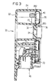
- the blind hole bottom 32 is one on the cover side Cylinder ring 36 pulled up over the cover 26 and the The height of the side wall 24 protrudes, as can be seen from FIG. 3 is.
- the cylinder ring 36 is forming a solid Segment section 38 formed with an asymmetrical interior, which will also be discussed later.
- the outside diameter the cylinder ring 36 is smaller than that Diameter of the outer circumference of the feedthrough 30 Blind hole wall.
- the cover 26 has a central opening 261 and is in the area down the opening 261 and part of the outer edges, i.e. towards the inside of the housing, forming support edges 262, 263 pulled. In the area of the corners are the Support edges widened to fastening tabs 264.
- the Cover 26 is shaped so that its inner support edge 263rd deeper than the outer support edge 262 and the mounting tabs 264 lies.
- the side wall 24 of the housing 20 is in the corner areas in Height of the circuit board 40 inwards to form support shoulders 72 drawn, which are shown in Figure 4. On these support shoulders 72 reach the cover 26 in the area the mounting tabs 264 for support.
- FIG. 2 illustrates the Assembly of cover 26, circuit board 40 and housing 20. Screw connections are used for this, i.e. these three parts will be assembled together using four screws 80, 82, 84, 86. Alternatively, only three screws can be used. For this purpose, the one additionally drawn in for illustration is used Screw 88 instead of screws 80 and 86. At the screwing process is described by the lid shape and the centrally provided support shoulder 70 the circuit board 40 clamped in the middle. This eliminates the one hand Screws or other fasteners for the circuit board and on the other hand there are vibrations of the circuit board prevented. By mounting the acceleration sensor 44 closer to a clamping point of the circuit board 40, ie in Near the edge, additional vibration protection can be added of the acceleration sensor can be created.
- the fastening and / or clamping the circuit board in the area of the central one Carrying out the housing or the cover provides an additional one Support point for the PCB, in the middle of the PCB, that with conventional control units by an additional Screw or similar had to be bought.
- the central one Clamping point fixes the circuit board in a central one Area that would otherwise show a strong tendency to vibrate would.
- the distances between which are decisive for the swing Fastening points are through the central clamping point kept low on all sides.
- the central clamping point enables also a ground connection from the circuit board to the housing 20 and the lid 26.
- Figure 5 illustrates a threaded weld stud 90 which welded to the schematically indicated body panel 100 and an asymmetrical head 92 with segment recess 94 and a shaft 96.
- the housing with the lid side on the shaft 96 of the welding stud 90 put on and is then due to the positive connection between the head 92 and the cylinder ring 36 then inevitably in the right orientation.
- the welding stud 90 has the task of the control unit 10 on Attach motor vehicle. It also serves as a diverting element for interference radiation.
Description
Die Erfindung betrifft ein Airbag-Steuergerät gemäß Oberbegriff des Anspruchs 1; (vgl. DE-A-4 111 883).The invention relates to an airbag control device according to the preamble of claim 1; (see DE-A-4 111 883).
Elektronische Steuergeräte für Personenschutzeinrichtungen in
Kraftfahrzeugen wie Airbags, Gurtstrammersysteme etc. umfassen
auf einer Leiterplatte diverse elektronische Bauteile,
die von einem deckelversehenen Gehäuse umschlossen sind, wie
beispielsweise in der DE 44 06 499 C2 beschrieben ist. Zur
Befestigung des Gehäuses am Kraftfahrzeug weist der Gehäusedeckel
Befestigungslaschen oder Flansche auf, über die außerdem
die Orientierung des Steuergeräts festgelegt wird. Diese
feste Orientierung des Steuergeräts ist zwingend, da der üblicherweise
verwendete Beschleunigungssensor eine vorgegebene
Empfindlichkeitsrichtung hat. Die Leiterplatte wird im Gehäuse
mittels Schrauben befestigt. Um sich aus langen Leitungswegen
ergebende Strahlung zu reduzieren, ist meist zentral am
Gehäuse eine Schraube als Ableitelement angebracht.Electronic control devices for personal protection devices in
Motor vehicles such as airbags, belt tensioners, etc. include
various electronic components on a circuit board,
which are enclosed by a cover-provided housing, such as
is described for example in
Der Erfindung liegt die Aufgabe zugrunde, eine Befestigung für ein Airbag-Steuergerät zu schaffen, die eine einfache, kosten günstige Montage des Steuergeräts gestattet, wobei auftretende Schwingungsprobleme im Bereich der Leiterplatte auf ein Minimum herabgesetzt sind.The invention has for its object a fastening for an airbag control unit that is simple, cost-effective assembly of the control unit allowed, whereby vibration problems occurring in the area of the circuit board are reduced to a minimum.
Diese Aufgabe ist erfindungsgemäß bei einem Airbag-Steuergerät mit den Merkmalen des Anspruchs 1 gelöst.This object is according to the invention in an airbag control unit solved with the features of claim 1.
Vorteilhafte weitere Ausgestaltungen der Erfindung sind Gegenstand der Unteransprüche.Advantageous further developments of the invention are the subject of subclaims.
Das erfindungsgemäße Airbag-Steuergerät kann unter Verwendung von kostengünstig herstellbaren Teilen, etwa einem Druckgußgehäuse und einem durch Tiefziehen hergestellten Deckel, schnell und mit wenigen Befestigungsteilen an der Fahrzeugkarosserie befestigt werden. Die Montage ist damit auch kostengünstig. Dies wird dadurch ermöglicht, daß erfindungsgemäß nur eine zentrale Befestigungsstelle für das komplette Steuergerät vorhanden ist, somit nur ein Befestigungsvorgang anstelle von bisher beispielsweise vier Schraubverbindungen erforderlich ist. Damit werden mindestens zwei Bolzen und Muttern, somit nicht nur Montagezeit, sondern auch Material eingespart.The airbag control device according to the invention can be used of inexpensive parts, such as a die-cast housing and a lid made by deep drawing, quickly and with few fastening parts on the vehicle body be attached. Installation is also inexpensive. This is made possible by the fact that the invention only one central attachment point for the complete control unit is present, so only one fastening process instead of previously four screw connections, for example is. This means that at least two bolts and nuts, not only assembly time, but also material saved.
Durch das Entfallen von bisher üblichen Befestigungslaschen steht mehr Raum für das Steuergerät selbst zur Verfügung, dessen Innenvolumen so vergrößert werden kann. Die Leiterplattenfläche kann vergrößert werden, so daß keine zweiseitige Leiterplattenbestückung oder Mehrlagenanordnung erforderlich ist.By eliminating the usual mounting tabs there is more space available for the control unit itself, whose internal volume can be increased. The circuit board area can be enlarged so that no two-sided PCB assembly or multi-layer arrangement required is.
Darüber hinaus ergibt sich durch die zentrale Befestigungsstelle
die Möglichkeit einer zentralen Einspannung der Leiterplatte.
Hierdurch können Schwingungen der Leiterplatte
deutlich reduziert oder sogar vermieden werden, die sich auf
den schwingungempfindlichen elektronischen Beschleunigungssensor
nachteilig auswirken, und es kann ggf. auf das Vergießen
des Beschleunigungssensors verzichtet werden, wie es in
der oben erwähnten DE 44 06 499 C2 beschrieben ist.In addition, there is the central attachment point
the possibility of central clamping of the circuit board.
This can cause vibration of the circuit board
that are significantly reduced or even avoided
the vibration-sensitive electronic acceleration sensor
adversely affect, and it can possibly on the shedding
the acceleration sensor can be dispensed with, as in
the above-mentioned
Wird eine formschlüssige Verbindung von Steuergerät und dem betreffenden Befestigungsteil mit asymmetrischer Form vorgesehen, ergibt sich automatisch eine verdrehsichere und lagegenaue Montage des Steuergeräts im Kraftfahrzeug.Is a positive connection between the control unit and the provided fastening part with asymmetrical shape, the result is automatically a twist-proof and precise position Installation of the control unit in the motor vehicle.
Ein Ausführungsbeispiel der Erfindung wird im folgenden anhand der Zeichnung erläutert. Es zeigen
- Figur 1:
- Eine perspektivische Draufsicht auf die Gehäusebodenseite eines Airbag-Steuergeräts,
- Figur 2:
- Eine perspektivische Ansicht auf die Deckelseite des Gehäuses,
- Figur 3:
- Eine Schnittansicht längs Linie B-B in Fig. 1,
- Figur 4:
- Eine Schnittansicht längs Linie A-A in Fig. 1 und
- Figur 5:
- Eine perspektivische Ansicht eines Gewindeschweißbolzens für die Montage des Gehäuses.
- Figure 1:
- A perspective top view of the housing bottom side of an airbag control unit,
- Figure 2:
- A perspective view of the cover side of the housing,
- Figure 3:
- 2 shows a sectional view along line BB in FIG. 1,
- Figure 4:
- A sectional view taken along line AA in Fig. 1 and
- Figure 5:
- A perspective view of a threaded weld stud for mounting the housing.
Ein Airbag-Steuergerät 10 umfaßt ein Gehäuse 20, z.B. ein
Aluminium-Druckgußgehäuse mit einem Boden 22, Seitenwänden 24
und einen beispielsweise aus Tiefziehblech hergestellten Dekkel
26. Das Gehäuse enthält eine Leiterplatte 40, auf der eine
Auswerteschaltung mit diversen Bauteilen 42 und ein mit
der Auswerteschaltung verbundener Beschleunigungssensor 44
angeordnet sind.
Ein Steckverbinder 46 dient als Schnittstelle und Anschluß
zum Airbag und anderen Steuergeräten im Kraftfahrzeug. Das
Gehäuse 20 weist eine zentrale Durchführung 30 auf, wobei der
Gehäuseboden 22 nach innen in das Gehäuse 20 eingezogen ist
und sich mit Anformteilen durch das Gehäuse hindurch bis zur
anderen Außenseite erstreckt.An
A
Mehr im einzelnen: Der Gehäuseboden 22 ist in der Gehäusemitte
nach innen gebogen, so daß er ein Sackloch mit einem Sacklochboden
32 mit einer mittigen Öffnung 34 bildet. Der Sacklochboden
32 befindet sich etwa in der Höhe der Leiterplatte
40 und weist auf der Gehäuseinnenseite eine Abstufung zum Ende
des Gehäusebodens 22 auf. Durch die Abstufung ist eine Auflageschulter
70 gebildet, auf deren Funktion noch eingegangen
wird. Der Sacklochboden 32 ist auf der Deckelseite zu einem
Zylinderring 36 hochgezogen, der über den Deckel 26 und die
Höhe der Seitenwand 24 vorsteht, wie aus Figur 3 zu ersehen
ist. Der Zylinderring 36 ist unter Bildung eines massiven
Segmentabschnitts 38 mit asymmetrischem Innenraum ausgebildet,
worauf ebenfalls später noch eingegangen wird. Der Außendurchmesser
des Zylinderrings 36 ist kleiner als der
Durchmesser des Außenumfangs der die Durchführung 30 bildenden
Sacklochwand. Wie die obige Beschreibung zeigt, ist die
zentrale Durchführung des Gehäuses 20 hermetisch gegen das
Gehäuseinnere abgeschirmt.More in detail: The
Der Deckel 26 weist eine zentrale Öffnung 261 auf und ist im-Bereich
der Öffnung 261 und eines Teils der Außenkanten nachunten,
d.h. zum Gehäuseinneren hin, unter Bildung von Auflagerändern
262, 263 gezogen. Im Bereich der Ecken sind die
Auflageränder zu Befestigungslaschen 264 verbreitert. Der
Deckel 26 ist so geformt, daß sein innerer Auflagerand 263
tiefer als der äußere Auflagerand 262 und die Befestigungslaschen
264 liegt.The
Die Seitenwand 24 des Gehäuses 20 ist in den Eckbereichen in
Höhe der Leiterplatte 40 nach innen unter Bildung von Auflageschultern
72 gezogen, die in Figur 4 dargestellt sind. Auf
diese Auflageschultern 72 gelangt der Deckel 26 im Bereich
der Befestigungslaschen 264 zur Auflage.The
Die perspektivische Ansicht von Figur 2 veranschaulicht den
Zusammenbau von Deckel 26, Leiterplatte 40 und Gehäuse 20.
Hierzu dienen Schraubverbindungen, d.h. diese drei Teile werden
gemeinsam mittels vier Schrauben 80, 82, 84, 86 montiert.
Alternativ können auch nur drei Schrauben verwendet werden.
Hierzu dient dann die zur Veranschaulichung zusätzlich eingezeichnete
Schraube 88 anstelle der Schrauben 80 und 86. Bei
dem Verschraubvorgang wird durch die beschriebene Deckelform
und die mittig vorgesehene Auflageschulter 70 die Leiterplatte
40 in der Mitte eingespannt. Dadurch entfallen zum einen
Schrauben oder sonstige Befestigungsmittel für die Leiterplatte
und zum anderen werden Schwingungen der Leiterplatte
verhindert. Durch die Montage des Beschleunigungssensors 44
näher an einer Einspannstelle der Leiterplatte 40, also in
Randnähe, kann noch zusätzlich ein weiterer Vibrationsschutz
des Beschleunigungssensors geschaffen werden. Das Befestigen
und/oder Einspannen der Leiterplatte im Bereich der zentralen
Durchführung am Gehäuse oder am Deckel verschafft einen zusätzlichen
Auflagerpunkt für die Leiterplatte, in Leiterplattenmitte,
der bei herkömmlichen Steuergeräten durch eine zusätzliche
Schraube o.ä. erkauft werden mußte. Die zentrale
Einspannstelle fixiert die Leiterplatte in einem zentralen
Bereich, der andernfalls starke Schwingungsneigung zeigen
würde. Die für das Schwingen maßgebenden Strecken zwischen
Befestigungspunkten sind durch die zentrale Einspannstelle
allseits gering gehalten. Die zentrale Einspannstelle ermöglicht
auch eine Masseanbindung von der Leiterplatte zum Gehäuse
20 und zum Deckel 26.The perspective view of Figure 2 illustrates the
Assembly of
Figur 5 veranschaulicht einen Gewindeschweißbolzen 90, der
mit dem schematisch angedeuteten Karosserieblech 100 verschweißt
ist und einen asymmetrischen Kopf 92 mit Segmentaussparung
94 sowie einen Schaft 96 aufweist.Figure 5 illustrates a threaded
Bei der Montage des Steuergeräts 10, d.h. des deckelversehenen
Gehäuses 20, an der Fahrzeugkarosserie wird das Gehäuse
mit der Deckelseite auf den Schaft 96 des Schweißbolzens 90
aufgesetzt und befindet sich dann aufgrund des Formschlusses
zwischen dem Kopf 92 und dem Zylinderring 36 dann zwangsläufig
in der richtigen Orientierung. Auf der Gegenseite, d.h.
im Sackloch der Durchführung 30 muß dann lediglich noch eine
Befestigungsmutter auf den Schaft 96 aufgeschraubt werden.
Der Schweißbolzen 90 hat die Aufgabe, das Steuergerät 10 am
Kraftfahrzeug zu befestigen. Darüber hinaus dient er als Ableitelement
für Störstrahlung.When installing the
Claims (10)
- Airbag control unit, with circuit board (40) carrying an electronic component (42), with a housing (20) for the circuit board (40) and with a cover (26) for the housing (20) and with means of mounting the control unit on a vehicle, whereby the housing (20) as a mounting has an essentially central passage (30), against which the inside of the housing is sealed, characterised in that the central passage (30) of the housing (20) extends through the circuit board (40) and the cover (26).
- Airbag control unit in accordance with claim 1, characterised in that the central passage (30) of the housing (20) has, at least in one area, an asymmetric shape which when positively connected to a mounting part (90) with a mating shape, forms a locating fixing.
- Airbag control unit in accordance with claim 1, characterised in that the circuit board (40) is held, fastened, on the housing (20) or on the cover (26) in the area of the central passage (30).
- Airbag control unit in accordance with claim 1, characterised in that in the area of the central passage (30) of the housing (20) a support (70) is provided for the circuit board (40) and the cover (26) is so shaped that it presses against the circuit board (40), thus providing a central clamping of the circuit board.
- Airbag control unit in accordance with claim 4, characterised in that the cover (26) is deeper than the outer rim in the area of the central housing passage (30).
- Airbag control unit in accordance with claim 5, characterised in that the central clamping point (70) of the circuit board has a ground connection to the housing (20) and cover (26).
- Airbag control unit in accordance with claim 3, characterised in that the circuit board (40) is held at at least one further point (80, 82, 84, 86) on the housing (20) or on the cover (26).
- Airbag control unit in accordance with claim 7, characterised in that the housing (20), the circuit board (40) and the cover (26) are bolted together.
- Airbag control unit in accordance with claim 1, characterised in that the circuit board carries an acceleration sensor.
- Airbag control unit in accordance with claims 3, 7 and 9, characterised in that the acceleration sensor is arranged between the central opening (30) and the further points (80, 82, 84, 86) on the circuit board (40).
Applications Claiming Priority (3)
| Application Number | Priority Date | Filing Date | Title |
|---|---|---|---|
| DE19638454 | 1996-09-19 | ||
| DE19638454 | 1996-09-19 | ||
| PCT/DE1997/001561 WO1998012904A1 (en) | 1996-09-19 | 1997-07-23 | Air bag control unit |
Publications (2)
| Publication Number | Publication Date |
|---|---|
| EP0927508A1 EP0927508A1 (en) | 1999-07-07 |
| EP0927508B1 true EP0927508B1 (en) | 2000-06-14 |
Family
ID=7806256
Family Applications (1)
| Application Number | Title | Priority Date | Filing Date |
|---|---|---|---|
| EP97935473A Expired - Lifetime EP0927508B1 (en) | 1996-09-19 | 1997-07-23 | Air bag control unit |
Country Status (6)
| Country | Link |
|---|---|
| US (1) | US6213495B1 (en) |
| EP (1) | EP0927508B1 (en) |
| JP (1) | JP3370682B2 (en) |
| KR (1) | KR100296235B1 (en) |
| DE (1) | DE59701895D1 (en) |
| WO (1) | WO1998012904A1 (en) |
Cited By (3)
| Publication number | Priority date | Publication date | Assignee | Title |
|---|---|---|---|---|
| DE102008002160A1 (en) | 2008-06-02 | 2009-12-03 | Robert Bosch Gmbh | Personal protective device for a vehicle and method for assembling a personal protective device for a vehicle |
| WO2010000523A1 (en) * | 2008-07-03 | 2010-01-07 | Robert Bosch Gmbh | Control unit for personal protection means for a vehicle and a method for assembling such a control unit |
| DE102008040157A1 (en) | 2008-07-03 | 2010-01-07 | Robert Bosch Gmbh | Personal protective device for a vehicle or method for assembling such a control device |
Families Citing this family (19)
| Publication number | Priority date | Publication date | Assignee | Title |
|---|---|---|---|---|
| DE19837833A1 (en) * | 1998-08-20 | 2000-02-10 | Daimler Chrysler Ag | Electronic unit with unit housing and at least one electric component for producing signal, first and second plug parts and at least one fixing facility |
| DE19841258C1 (en) * | 1998-09-09 | 2000-03-16 | Siemens Ag | Automobile air-bag control device |
| WO2000032022A1 (en) * | 1998-11-24 | 2000-06-02 | Continental Teves Ag & Co. Ohg | Protective arrangement for electronic functional units and/or functional groups |
| DE19911990A1 (en) * | 1999-03-17 | 2000-09-28 | Trw Automotive Electron & Comp | Metal housing, in particular for an airbag control unit |
| DE19911989C2 (en) * | 1999-03-17 | 2003-04-24 | Trw Automotive Electron & Comp | metal housing |
| DE29918914U1 (en) * | 1999-10-27 | 2000-03-09 | Trw Automotive Electron & Comp | Control device for occupant restraint systems in vehicles |
| DE20019524U1 (en) * | 2000-11-17 | 2001-03-29 | Trw Automotive Electron & Comp | Housing system for safety-related control units in motor vehicles |
| US6913472B2 (en) | 2002-06-28 | 2005-07-05 | Siemens Vdo Automotive Corporation | Method and apparatus for attaching a sensor assembly in a control unit |
| DE10238528A1 (en) * | 2002-08-22 | 2004-03-04 | Robert Bosch Gmbh | mounting assembly |
| US20060288464A1 (en) * | 2005-06-24 | 2006-12-28 | Warden Matthew P | Personal protection device |
| DE102009045565A1 (en) * | 2009-10-12 | 2011-04-14 | Robert Bosch Gmbh | Adapter plate for mounting a housing in a vehicle and corresponding control unit |
| FR2978098A3 (en) * | 2011-07-20 | 2013-01-25 | Renault Sa | Electronic device for controlling safety system e.g. airbag, of vehicle i.e. car, has member i.e. pin, inserted in through-hole, where pin projects from securing element via through-hole for fixing device on securing element of vehicle body |
| JP5629384B2 (en) * | 2011-09-22 | 2014-11-19 | オートリブ ディベロップメント エービー | Electronic circuit device for airbag deployment |
| ITTO20111168A1 (en) * | 2011-12-19 | 2013-06-20 | Gate Srl | ELECTRONIC UNIT, IN PARTICULAR CONTROL UNIT FOR THE ENGINE OF AN ELECTRIC FAN |
| JP6257881B2 (en) * | 2012-05-31 | 2018-01-10 | 株式会社ミクニ | Engine control unit |
| JP5747894B2 (en) * | 2012-11-01 | 2015-07-15 | 株式会社デンソー | Case for electronic device |
| WO2015022730A1 (en) * | 2013-08-13 | 2015-02-19 | 三菱電機株式会社 | Electronic apparatus |
| US10788509B2 (en) * | 2017-06-09 | 2020-09-29 | Simmonds Precision Products, Inc. | High frequency accelerometer housing including circuit board disposed directly above support pad |
| CN114497942B (en) * | 2021-12-06 | 2023-07-25 | 深圳市鸿富胜科技有限公司 | Combiner for communication base station |
Family Cites Families (17)
| Publication number | Priority date | Publication date | Assignee | Title |
|---|---|---|---|---|
| JPS5111172Y2 (en) * | 1971-05-10 | 1976-03-25 | ||
| US3774938A (en) * | 1972-09-25 | 1973-11-27 | Gen Motors Corp | Velocity responsive sensor for vehicle occupant restraints |
| JPS5331161Y2 (en) * | 1973-08-17 | 1978-08-03 | ||
| DE2813457A1 (en) * | 1978-03-29 | 1979-10-11 | Bosch Gmbh Robert | Fail=safe release circuit for vehicle air bag - has low-pass filter and is mounted in HF shielding housing |
| DE8215422U1 (en) * | 1982-05-27 | 1982-09-23 | Robert Bosch Gmbh, 7000 Stuttgart | Electronic control device, in particular for motor vehicles |
| DE3319724A1 (en) * | 1983-05-31 | 1984-12-06 | Özgürgil, Murat, 8028 Taufkirchen | Boiling, baking/roasting and grilling appliance with grilling device (compact appliance) with interchangeable coal, gas and electric heating source device for camping, the household and gastronomy |
| EP0195832B1 (en) * | 1985-03-23 | 1989-06-07 | Petri AG | Steering wheel with a current conduction to a shock-preventing airbag-safety system situated in a steering-wheel bowl |
| US4811168A (en) * | 1987-11-23 | 1989-03-07 | Chesnut Milton L | Housing and connector apparatus for electronic circuit |
| JPH03253440A (en) * | 1990-03-01 | 1991-11-12 | Zexel Corp | Control system for vehicle safety device |
| GB2242871B (en) * | 1990-04-12 | 1994-05-04 | Autoliv Dev | Improvements in or relating to an air-bag arrangement |
| JPH04342638A (en) * | 1991-05-17 | 1992-11-30 | Nippon Oil & Fats Co Ltd | Air bag device |
| US5327796A (en) * | 1992-12-28 | 1994-07-12 | General Motors Corporation | Horn switch actuated by rocking air bag module |
| DE4406499C2 (en) * | 1994-02-28 | 1996-02-08 | Siemens Ag | Sensor unit for controlling an occupant protection system of a motor vehicle |
| FR2728847B1 (en) * | 1994-12-28 | 1997-01-31 | Sagem Autoliv | VEHICLE AIR BAG CALCULATOR |
| US5590900A (en) * | 1995-07-21 | 1997-01-07 | Avibank Mfg., Inc. | Air bag mounting system |
| US5873597A (en) * | 1996-02-07 | 1999-02-23 | Robert Bosch Corporation | Modular sensor unit console |
| DE19622228C1 (en) * | 1996-06-03 | 1997-06-26 | Kostal Leopold Gmbh & Co Kg | Device for signal transmission to or from motor vehicle steering column |
-
1997
- 1997-07-23 DE DE59701895T patent/DE59701895D1/en not_active Expired - Fee Related
- 1997-07-23 JP JP51413298A patent/JP3370682B2/en not_active Expired - Fee Related
- 1997-07-23 WO PCT/DE1997/001561 patent/WO1998012904A1/en active IP Right Grant
- 1997-07-23 EP EP97935473A patent/EP0927508B1/en not_active Expired - Lifetime
-
1999
- 1999-03-17 KR KR1019997002255A patent/KR100296235B1/en not_active IP Right Cessation
- 1999-03-19 US US09/272,963 patent/US6213495B1/en not_active Expired - Fee Related
Cited By (5)
| Publication number | Priority date | Publication date | Assignee | Title |
|---|---|---|---|---|
| DE102008002160A1 (en) | 2008-06-02 | 2009-12-03 | Robert Bosch Gmbh | Personal protective device for a vehicle and method for assembling a personal protective device for a vehicle |
| WO2010000523A1 (en) * | 2008-07-03 | 2010-01-07 | Robert Bosch Gmbh | Control unit for personal protection means for a vehicle and a method for assembling such a control unit |
| DE102008040156A1 (en) | 2008-07-03 | 2010-01-07 | Robert Bosch Gmbh | Personal protective device for a vehicle and a method for assembling such a control device |
| DE102008040157A1 (en) | 2008-07-03 | 2010-01-07 | Robert Bosch Gmbh | Personal protective device for a vehicle or method for assembling such a control device |
| CN102076529B (en) * | 2008-07-03 | 2014-03-05 | 罗伯特·博世有限公司 | Control unit for personal protection means for vehicle and method for assembling such control unit |
Also Published As
| Publication number | Publication date |
|---|---|
| DE59701895D1 (en) | 2000-07-20 |
| WO1998012904A1 (en) | 1998-03-26 |
| JP2000502639A (en) | 2000-03-07 |
| KR100296235B1 (en) | 2001-08-07 |
| EP0927508A1 (en) | 1999-07-07 |
| JP3370682B2 (en) | 2003-01-27 |
| US6213495B1 (en) | 2001-04-10 |
| KR20000036200A (en) | 2000-06-26 |
Similar Documents
| Publication | Publication Date | Title |
|---|---|---|
| EP0927508B1 (en) | Air bag control unit | |
| DE10104568B4 (en) | Mounting structure of a printed circuit board for an electronic control unit | |
| DE4121263C2 (en) | Holder for an auxiliary device on an engine, in particular a motor vehicle engine | |
| DE4134673C1 (en) | ||
| DE19530941A1 (en) | Motor vehicle door with mirror using insertion bolt mounting | |
| DE202007013477U1 (en) | Driver alarm system for the steering wheel of a motor vehicle | |
| DE102004016997A1 (en) | Sealed air filter assembly | |
| DE102015206482A1 (en) | control unit | |
| EP0193862B1 (en) | External rear view mirror for a vehicle | |
| DE102004001098A1 (en) | Piezoelectric material for dampening vibrations of a dashboard and / or a steering column | |
| EP3931539B1 (en) | Torque sensor unit comprising a magnetic shield | |
| EP1949041B1 (en) | Acceleration sensor | |
| EP0348618B1 (en) | Mounting device | |
| DE3323624A1 (en) | Housing for equipment sensitive to vibration and impact | |
| DE19845777A1 (en) | Airbag fixture for vehicles | |
| DE3013684C2 (en) | Knock sensor | |
| DE102008037278A1 (en) | Electronic control device for regulating e.g. airbag, in motor vehicle, has housing, connection unit and mount that are mechanically fixed in stiffening frame at region of sensor, where device is mechanically mounted on mounting surface | |
| DE102009023317A1 (en) | Electronic control device for controlling e.g. airbag in motor vehicle, has reinforcement frames at which housing, connecting unit and carrier are mechanically fastened in region of sensor, where carrier is formed as printed circuit board | |
| EP0803409B1 (en) | Passenger air bag module | |
| DE102018105501A1 (en) | Shielding device for an ultrasonic sensor device and method for producing an ultrasonic sensor device | |
| DE4230710C2 (en) | Device for sealing between the oil pan and crankcase of an internal combustion engine | |
| DE602004011103T2 (en) | ENGINE STORAGE DEVICE | |
| DE4005090C2 (en) | ||
| DE112019007684T5 (en) | electrical device | |
| DE102016010825B4 (en) | Casing for holding a radar device |
Legal Events
| Date | Code | Title | Description |
|---|---|---|---|
| PUAI | Public reference made under article 153(3) epc to a published international application that has entered the european phase |
Free format text: ORIGINAL CODE: 0009012 |
|
| 17P | Request for examination filed |
Effective date: 19990304 |
|
| AK | Designated contracting states |
Kind code of ref document: A1 Designated state(s): DE FR GB IT |
|
| GRAG | Despatch of communication of intention to grant |
Free format text: ORIGINAL CODE: EPIDOS AGRA |
|
| 17Q | First examination report despatched |
Effective date: 19991102 |
|
| GRAG | Despatch of communication of intention to grant |
Free format text: ORIGINAL CODE: EPIDOS AGRA |
|
| GRAH | Despatch of communication of intention to grant a patent |
Free format text: ORIGINAL CODE: EPIDOS IGRA |
|
| GRAH | Despatch of communication of intention to grant a patent |
Free format text: ORIGINAL CODE: EPIDOS IGRA |
|
| GRAA | (expected) grant |
Free format text: ORIGINAL CODE: 0009210 |
|
| AK | Designated contracting states |
Kind code of ref document: B1 Designated state(s): DE FR GB IT |
|
| REF | Corresponds to: |
Ref document number: 59701895 Country of ref document: DE Date of ref document: 20000720 |
|
| GBT | Gb: translation of ep patent filed (gb section 77(6)(a)/1977) |
Effective date: 20000710 |
|
| ITF | It: translation for a ep patent filed |
Owner name: STUDIO JAUMANN P. & C. S.N.C. |
|
| ET | Fr: translation filed | ||
| PLBE | No opposition filed within time limit |
Free format text: ORIGINAL CODE: 0009261 |
|
| STAA | Information on the status of an ep patent application or granted ep patent |
Free format text: STATUS: NO OPPOSITION FILED WITHIN TIME LIMIT |
|
| 26N | No opposition filed | ||
| REG | Reference to a national code |
Ref country code: GB Ref legal event code: IF02 |
|
| PGFP | Annual fee paid to national office [announced via postgrant information from national office to epo] |
Ref country code: FR Payment date: 20090716 Year of fee payment: 13 |
|
| PGFP | Annual fee paid to national office [announced via postgrant information from national office to epo] |
Ref country code: GB Payment date: 20090720 Year of fee payment: 13 Ref country code: DE Payment date: 20090731 Year of fee payment: 13 |
|
| PGFP | Annual fee paid to national office [announced via postgrant information from national office to epo] |
Ref country code: IT Payment date: 20090725 Year of fee payment: 13 |
|
| GBPC | Gb: european patent ceased through non-payment of renewal fee |
Effective date: 20100723 |
|
| REG | Reference to a national code |
Ref country code: FR Ref legal event code: ST Effective date: 20110331 |
|
| PG25 | Lapsed in a contracting state [announced via postgrant information from national office to epo] |
Ref country code: DE Free format text: LAPSE BECAUSE OF NON-PAYMENT OF DUE FEES Effective date: 20110201 |
|
| REG | Reference to a national code |
Ref country code: DE Ref legal event code: R119 Ref document number: 59701895 Country of ref document: DE Effective date: 20110201 |
|
| PG25 | Lapsed in a contracting state [announced via postgrant information from national office to epo] |
Ref country code: IT Free format text: LAPSE BECAUSE OF NON-PAYMENT OF DUE FEES Effective date: 20100723 Ref country code: FR Free format text: LAPSE BECAUSE OF NON-PAYMENT OF DUE FEES Effective date: 20100802 |
|
| PG25 | Lapsed in a contracting state [announced via postgrant information from national office to epo] |
Ref country code: GB Free format text: LAPSE BECAUSE OF NON-PAYMENT OF DUE FEES Effective date: 20100723 |