EP0926338A1 - Gerät zur Messung des Ionisationsstromes einer Brennkammer - Google Patents
Gerät zur Messung des Ionisationsstromes einer Brennkammer Download PDFInfo
- Publication number
- EP0926338A1 EP0926338A1 EP98403207A EP98403207A EP0926338A1 EP 0926338 A1 EP0926338 A1 EP 0926338A1 EP 98403207 A EP98403207 A EP 98403207A EP 98403207 A EP98403207 A EP 98403207A EP 0926338 A1 EP0926338 A1 EP 0926338A1
- Authority
- EP
- European Patent Office
- Prior art keywords
- antenna
- combustion chamber
- spark plug
- measuring device
- combustion
- Prior art date
- Legal status (The legal status is an assumption and is not a legal conclusion. Google has not performed a legal analysis and makes no representation as to the accuracy of the status listed.)
- Granted
Links
Images


Classifications
-
- F—MECHANICAL ENGINEERING; LIGHTING; HEATING; WEAPONS; BLASTING
- F02—COMBUSTION ENGINES; HOT-GAS OR COMBUSTION-PRODUCT ENGINE PLANTS
- F02P—IGNITION, OTHER THAN COMPRESSION IGNITION, FOR INTERNAL-COMBUSTION ENGINES; TESTING OF IGNITION TIMING IN COMPRESSION-IGNITION ENGINES
- F02P17/00—Testing of ignition installations, e.g. in combination with adjusting; Testing of ignition timing in compression-ignition engines
- F02P17/12—Testing characteristics of the spark, ignition voltage or current
-
- G—PHYSICS
- G01—MEASURING; TESTING
- G01N—INVESTIGATING OR ANALYSING MATERIALS BY DETERMINING THEIR CHEMICAL OR PHYSICAL PROPERTIES
- G01N27/00—Investigating or analysing materials by the use of electric, electrochemical, or magnetic means
- G01N27/62—Investigating or analysing materials by the use of electric, electrochemical, or magnetic means by investigating the ionisation of gases, e.g. aerosols; by investigating electric discharges, e.g. emission of cathode
- G01N27/626—Investigating or analysing materials by the use of electric, electrochemical, or magnetic means by investigating the ionisation of gases, e.g. aerosols; by investigating electric discharges, e.g. emission of cathode using heat to ionise a gas
-
- G—PHYSICS
- G01—MEASURING; TESTING
- G01R—MEASURING ELECTRIC VARIABLES; MEASURING MAGNETIC VARIABLES
- G01R19/00—Arrangements for measuring currents or voltages or for indicating presence or sign thereof
- G01R19/0046—Arrangements for measuring currents or voltages or for indicating presence or sign thereof characterised by a specific application or detail not covered by any other subgroup of G01R19/00
- G01R19/0061—Measuring currents of particle-beams, currents from electron multipliers, photocurrents, ion currents; Measuring in plasmas
-
- G—PHYSICS
- G01—MEASURING; TESTING
- G01R—MEASURING ELECTRIC VARIABLES; MEASURING MAGNETIC VARIABLES
- G01R31/00—Arrangements for testing electric properties; Arrangements for locating electric faults; Arrangements for electrical testing characterised by what is being tested not provided for elsewhere
- G01R31/005—Testing of electric installations on transport means
- G01R31/006—Testing of electric installations on transport means on road vehicles, e.g. automobiles or trucks
Definitions
- the present invention relates to a device for measuring the ionization current in a room combustion.
- JP documents 129534/93 and JP 129796/93 disclose embodiments of a detector, but do not specify how the measurement should be made to offer the best quality.
- the present invention therefore relates to a ionization current measuring device which improves the performance of known devices date, offering excellent sensitivity of measuring and limiting the disturbances caused by ignition sparks.
- the current measurement device ionization in a combustion chamber of internal combustion engine with positive ignition is of the type comprising a candle with a central electrode connected to means of electrical supply and inserted in a pellet via an insulator, and at least one antenna opening into the room at neighborhood of the candle, this antenna cooperating with measurement means and polarization means.
- the measuring device of the ionization current in a combustion is characterized in that the means of antenna polarization are shaped to polarize the latter to an electrical potential positive adapted, so as to collect the current generated by negative ionized species present in the combustion chamber and generated by the combustion of the fuel mixture initiated by the triggering of an electric arc between the electrode central and the base of the candle.
- the means of electrical supply to the electrode candle center are shaped to polarize negatively said central electrode.
- the means of antenna polarization are shaped to polarize the latter to an electrical potential positive of a few tens of volts.
- the means of electrical supply to the electrode candle center are shaped to polarize positively said central electrode.
- the antenna polarization means are conformed to polarize the antenna at an electrical potential positive significantly higher than that substantially stable spark plug center electrode next the ignition peak of the electric arc.
- the means of electrical supply to the electrode candle center are shaped to continue polarizing said electrode after the end of the arc electric.
- the means of electrical supply to the electrode central candle are shaped to control the duration of the electric arc.
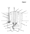
- This candle 1 is conventionally constituted a base 2, an electrical insulator 5, and a central electrode 4.
- the central electrode 4 is connected to means 23 allowing generation, to a predetermined instant, of an electric arc 17 between the central electrode 4 and a point on the base 2, for example a rod 16.
- a voltage source 22 ensures the polarization of the antenna 12 by compared to base 2 and cylinder head 7.
- a sleeve insulator 13 in alumina-based ceramic, ensures the electrical insulation of the antenna 12 with respect to the whole environment except the bedroom combustion 3, the measuring device 15, and the polarization means 22.
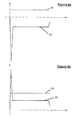
- the difference of potential generated by means 23 between the central electrode 4 and the base 2 reaches a peak very high absolute value (around ten thousand volts) during the short interval required to the establishment of the electric arc 17, then falls back to a more modest value (a few hundred absolute volts) where it stabilizes during the rest of the duration of arc 17.
- a peak very high absolute value around ten thousand volts
- a more modest value a few hundred absolute volts
- the antenna 12 Due to the existence of a difference of potential between the antenna 12 polarized by means 22 and the combustion gases 19, the antenna 12 therefore captures one of these two kinds of species; he an ionization current is thus established, the characteristics depend on the nature of the gases combustion and therefore the quality of combustion.
- the antenna 12 is according to the invention, polarized at a positive potential higher than those of base 2 and cylinder head 7, so as to capture the negatively charged species 21, which, appearing more mobile than charged species positively 20, are easier to collect and thus guarantee an excellent sensitivity of measured.
- the bias potential 26 can therefore be chosen to an arbitrary positive value, by example a few volts or a few dozen volts, to achieve the desired effect of capturing negatively charged ionic species from the start of combustion. It is even possible not to polarize the antenna 12 by an external source and the leave at floating potential.
- the low level of potential applied to antenna 12 therefore allows mounting particularly simple.
- the potential for polarization 22 of antenna 12 must be chosen greater than the potential of the central electrode 4 after the initiation peak of arc 17. This provision then ensures that the antenna 12 attracts negatively charged species 21 preferentially to the central electrode 4.
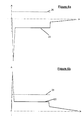
- the polarization potential 26 of the antenna 12 is therefore chosen at a positive value arbitrary about a few hundred volts, this which significantly complicates the assembly compared to the solution described in relation to Figure 4a since the required voltage level is high.
- the quality of the current measurement ionization is related to the potential difference between the antenna 12 and the combustion gases which are are polarized by the central electrode 4, therefore plus the return to 0 V of the electrode potential 4 is slow and the longer it is possible to extend in time the measurement of the ionization current without have to use a high bias potential for antenna 12, even not to polarize the antenna by an external source and leave it at floating potential.
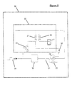
- the arc 17 in the candle 1 takes place when the transistor 34, on receipt of the control signal 29, closes the primary circuit 27 of the coil, which generates a high voltage current in the secondary 28 of the coil.
- the command 29, consisting of a positive niche of voltage is received by a retarder 30 whose delay time is equal to the duration of the signal command 29 added to the desired duration of the arc 17.
- This delay means that immediately before the self-timer 30 transmits the control 29 to the field effect transistor 32, the primary circuit 27 of the coil is open, the resistance 33 having the effect of maintaining the terminals of transistor 32 at neighboring potentials.
- the capacity 31 has the effect of adding the potentials of the control signal 29 and of the primary 27 supply of the coil and bring the potential of the gate of transistor 32 to this value.
- the transistor short-circuits primary of the coil 27 having at its terminals a potential of the order of a volt, which generates a potential difference in the secondary of the coil 28 of about 100 volts, lower than that necessary for the establishment of arc 17, and again polarizes the central electrode 4 with a potential gradually evolving towards 0 V up to what all of the electrical energy present in the primary circuit be dissipated in the transistor 32, cf.
- Figures 6a and 6b are the effect of adding the potentials of the control signal 29 and of the primary 27 supply of the coil and bring the potential of the gate of transistor 32 to this value.
- the device object of the invention it is possible to measure the current ionization generated in a combustion chamber during the combustion of the fuel mixture by a antenna integrated in the spark plug, from the arrival of the flame on the antenna even in presence of the ignition electric arc.
- the present invention can apply regardless of the number of antennas used. It may indeed be preferable use multiple antennas to appreciate more precisely the course of combustion.
- the antenna (s) used for measure the ionization current may not be carried by the spark plug base, or the antennas being for example located directly through the cylinder head.
Applications Claiming Priority (2)
| Application Number | Priority Date | Filing Date | Title |
|---|---|---|---|
| FR9716128A FR2772922B1 (fr) | 1997-12-19 | 1997-12-19 | Dispositif de mesure du courant d'ionisation dans une chambre de combustion |
| FR9716128 | 1997-12-19 |
Publications (2)
| Publication Number | Publication Date |
|---|---|
| EP0926338A1 true EP0926338A1 (de) | 1999-06-30 |
| EP0926338B1 EP0926338B1 (de) | 2003-08-13 |
Family
ID=9514818
Family Applications (1)
| Application Number | Title | Priority Date | Filing Date |
|---|---|---|---|
| EP19980403207 Expired - Lifetime EP0926338B1 (de) | 1997-12-19 | 1998-12-18 | Gerät zur Messung des Ionisationsstromes einer Brennkammer |
Country Status (3)
| Country | Link |
|---|---|
| EP (1) | EP0926338B1 (de) |
| DE (1) | DE69817134T2 (de) |
| FR (1) | FR2772922B1 (de) |
Cited By (2)
| Publication number | Priority date | Publication date | Assignee | Title |
|---|---|---|---|---|
| EP2732142A4 (de) * | 2011-07-15 | 2015-03-04 | Univ Wayne State | Gleichzeitige ionenmessung und gasprobennahme bei verbrennungsmotorzylindern und anderen verbrennungssystemen |
| WO2018098278A1 (en) | 2016-11-22 | 2018-05-31 | Ic Llc | Spark plug combustion ionization sensor |
Citations (3)
| Publication number | Priority date | Publication date | Assignee | Title |
|---|---|---|---|---|
| US5180983A (en) * | 1990-09-27 | 1993-01-19 | Mitsubishi Denki K.K. | Ignition plug for an internal combustion engine provided with an ionization current detector electrode |
| US5271268A (en) * | 1990-11-26 | 1993-12-21 | Mitsubishi Denki Kabushiki Kaisha | Ionic current sensing apparatus |
| EP0627622A2 (de) * | 1993-05-31 | 1994-12-07 | Ngk Spark Plug Co., Ltd | Ionisierungsfühler für Verbrennungsmotoren |
-
1997
- 1997-12-19 FR FR9716128A patent/FR2772922B1/fr not_active Expired - Fee Related
-
1998
- 1998-12-18 EP EP19980403207 patent/EP0926338B1/de not_active Expired - Lifetime
- 1998-12-18 DE DE69817134T patent/DE69817134T2/de not_active Expired - Lifetime
Patent Citations (3)
| Publication number | Priority date | Publication date | Assignee | Title |
|---|---|---|---|---|
| US5180983A (en) * | 1990-09-27 | 1993-01-19 | Mitsubishi Denki K.K. | Ignition plug for an internal combustion engine provided with an ionization current detector electrode |
| US5271268A (en) * | 1990-11-26 | 1993-12-21 | Mitsubishi Denki Kabushiki Kaisha | Ionic current sensing apparatus |
| EP0627622A2 (de) * | 1993-05-31 | 1994-12-07 | Ngk Spark Plug Co., Ltd | Ionisierungsfühler für Verbrennungsmotoren |
Cited By (4)
| Publication number | Priority date | Publication date | Assignee | Title |
|---|---|---|---|---|
| EP2732142A4 (de) * | 2011-07-15 | 2015-03-04 | Univ Wayne State | Gleichzeitige ionenmessung und gasprobennahme bei verbrennungsmotorzylindern und anderen verbrennungssystemen |
| US9945812B2 (en) | 2011-07-15 | 2018-04-17 | Wayne State University | Simultaneous ion sensing and gas sampling in combustion engine cylinders and other combustion systems |
| WO2018098278A1 (en) | 2016-11-22 | 2018-05-31 | Ic Llc | Spark plug combustion ionization sensor |
| EP3545187A4 (de) * | 2016-11-22 | 2020-07-22 | Ic Llc | Verbrennungsionisierungssensor für zündkerze |
Also Published As
| Publication number | Publication date |
|---|---|
| DE69817134D1 (de) | 2003-09-18 |
| DE69817134T2 (de) | 2004-06-09 |
| FR2772922A1 (fr) | 1999-06-25 |
| EP0926338B1 (de) | 2003-08-13 |
| FR2772922B1 (fr) | 2000-03-03 |
Similar Documents
| Publication | Publication Date | Title |
|---|---|---|
| EP2205858B1 (de) | Vorrichtung zur messung des ionisationsstromes in einem radiofrequenz-zündsystem für einen brennkraftmotor | |
| FR2667362A1 (fr) | Systeme d'allumage direct pour moteur a combustion interne et ensemble a bobine. | |
| FR2910730A1 (fr) | Systeme d'allumage a plasma | |
| EP2002117B1 (de) | Verfahren zur messung eines ionisierungsstromes einer zündkerze mit resonanzstruktur und entsprechende vorrichtung | |
| CA1118833A (fr) | Circuit electrique pour l'allumage d'un detonateur | |
| FR2575871A1 (fr) | Paratonnerre a decharge couronne impulsionnelle intermittente | |
| FR2864172A1 (fr) | Circuit de detection d'ionisation a double etage | |
| FR2878086A1 (fr) | Bougie a plasma radiofrequence | |
| FR2777607A1 (fr) | Systeme d'allumage a energie commandee pour un moteur a combustion interne | |
| WO2010029238A1 (fr) | Dispositif de mesure du courant d'ionisation dans un systeme d'allumage radiofrequence pour un moteur a combustion interne | |
| EP0926338B1 (de) | Gerät zur Messung des Ionisationsstromes einer Brennkammer | |
| EP0260177B1 (de) | Vorrichtung zum Aufspüren von unregelmässigen Schwankungen der Verbrennung in den Verbrennungsräumen eines Ottomotors mit gesteuerter Zündung | |
| US20130125558A1 (en) | Preheating a spark plug | |
| FR2827916A1 (fr) | Procede pour controler les parametres d'allumage d'une bougie d'allumage pour moteur a combustion interne et dispositif d'allumage utilisant un tel procede | |
| WO2007066031A1 (fr) | Procede et dispositif de diagnostic d'une bobine d'allumage d'un moteur a combustion interne | |
| EP0268528B1 (de) | Zündanlage für Brennkraftmaschine | |
| FR3049780A1 (fr) | Procede et dispositif pour la regeneration d'une bougie d'allumage a semi-conducteur | |
| FR2946190A1 (fr) | Procede de detection du type d'etincelle generee par une bobine-bougie d'allumage radiofrequence, et dispositif correspondant. | |
| EP0866917A2 (de) | Vorrichtung zur überwachung des zündsystems einer brennkraftmaschine | |
| EP0199616B1 (de) | Vorrichtung zum Überprüfen der Zündung einer pyrotechnischen Ladung | |
| EP1628377A1 (de) | Schutzvorrichtung für elektrische Anlagen gegen Überspannungen einschliesslich einer Funkenstrecke mit Zündschaltung | |
| FR2531283A1 (fr) | Commutateur d'ionisation a auto-excitation des impulsions d'energie a haute tension dans un systeme d'allumage de moteur a carburateur | |
| CH655791A5 (fr) | Fusee electrique de projectile a percussion. | |
| FR3124886A1 (fr) | Ensemble coupe-circuit pyrotechnique pour aeronef, et aeronef comprenant un tel ensemble. | |
| WO2018060592A1 (fr) | Procede de test d'une bougie d'allumage a semi-conducteur |
Legal Events
| Date | Code | Title | Description |
|---|---|---|---|
| PUAI | Public reference made under article 153(3) epc to a published international application that has entered the european phase |
Free format text: ORIGINAL CODE: 0009012 |
|
| AK | Designated contracting states |
Kind code of ref document: A1 Designated state(s): DE ES GB IT |
|
| AX | Request for extension of the european patent |
Free format text: AL;LT;LV;MK;RO;SI |
|
| 17P | Request for examination filed |
Effective date: 19991129 |
|
| AKX | Designation fees paid |
Free format text: DE ES GB IT |
|
| GRAG | Despatch of communication of intention to grant |
Free format text: ORIGINAL CODE: EPIDOS AGRA |
|
| 17Q | First examination report despatched |
Effective date: 20020624 |
|
| RAP1 | Party data changed (applicant data changed or rights of an application transferred) |
Owner name: RENAULT S.A.S. |
|
| GRAG | Despatch of communication of intention to grant |
Free format text: ORIGINAL CODE: EPIDOS AGRA |
|
| GRAH | Despatch of communication of intention to grant a patent |
Free format text: ORIGINAL CODE: EPIDOS IGRA |
|
| GRAH | Despatch of communication of intention to grant a patent |
Free format text: ORIGINAL CODE: EPIDOS IGRA |
|
| GRAA | (expected) grant |
Free format text: ORIGINAL CODE: 0009210 |
|
| AK | Designated contracting states |
Designated state(s): DE ES GB IT |
|
| PG25 | Lapsed in a contracting state [announced via postgrant information from national office to epo] |
Ref country code: IT Free format text: LAPSE BECAUSE OF FAILURE TO SUBMIT A TRANSLATION OF THE DESCRIPTION OR TO PAY THE FEE WITHIN THE PRESCRIBED TIME-LIMIT;WARNING: LAPSES OF ITALIAN PATENTS WITH EFFECTIVE DATE BEFORE 2007 MAY HAVE OCCURRED AT ANY TIME BEFORE 2007. THE CORRECT EFFECTIVE DATE MAY BE DIFFERENT FROM THE ONE RECORDED. Effective date: 20030813 Ref country code: GB Free format text: LAPSE BECAUSE OF FAILURE TO SUBMIT A TRANSLATION OF THE DESCRIPTION OR TO PAY THE FEE WITHIN THE PRESCRIBED TIME-LIMIT Effective date: 20030813 |
|
| REG | Reference to a national code |
Ref country code: GB Ref legal event code: FG4D Free format text: NOT ENGLISH |
|
| REF | Corresponds to: |
Ref document number: 69817134 Country of ref document: DE Date of ref document: 20030918 Kind code of ref document: P |
|
| PG25 | Lapsed in a contracting state [announced via postgrant information from national office to epo] |
Ref country code: ES Free format text: LAPSE BECAUSE OF FAILURE TO SUBMIT A TRANSLATION OF THE DESCRIPTION OR TO PAY THE FEE WITHIN THE PRESCRIBED TIME-LIMIT Effective date: 20031124 |
|
| GBV | Gb: ep patent (uk) treated as always having been void in accordance with gb section 77(7)/1977 [no translation filed] |
Effective date: 20030813 |
|
| PLBE | No opposition filed within time limit |
Free format text: ORIGINAL CODE: 0009261 |
|
| STAA | Information on the status of an ep patent application or granted ep patent |
Free format text: STATUS: NO OPPOSITION FILED WITHIN TIME LIMIT |
|
| 26N | No opposition filed |
Effective date: 20040514 |
|
| PGFP | Annual fee paid to national office [announced via postgrant information from national office to epo] |
Ref country code: DE Payment date: 20141211 Year of fee payment: 17 |
|
| REG | Reference to a national code |
Ref country code: DE Ref legal event code: R119 Ref document number: 69817134 Country of ref document: DE |
|
| PG25 | Lapsed in a contracting state [announced via postgrant information from national office to epo] |
Ref country code: DE Free format text: LAPSE BECAUSE OF NON-PAYMENT OF DUE FEES Effective date: 20160701 |