EP0926338A1 - Device for measuring the ionisation current in a combustion chamber - Google Patents
Device for measuring the ionisation current in a combustion chamber Download PDFInfo
- Publication number
- EP0926338A1 EP0926338A1 EP98403207A EP98403207A EP0926338A1 EP 0926338 A1 EP0926338 A1 EP 0926338A1 EP 98403207 A EP98403207 A EP 98403207A EP 98403207 A EP98403207 A EP 98403207A EP 0926338 A1 EP0926338 A1 EP 0926338A1
- Authority
- EP
- European Patent Office
- Prior art keywords
- antenna
- combustion chamber
- spark plug
- measuring device
- combustion
- Prior art date
- Legal status (The legal status is an assumption and is not a legal conclusion. Google has not performed a legal analysis and makes no representation as to the accuracy of the status listed.)
- Granted
Links
Images


Classifications
-
- F—MECHANICAL ENGINEERING; LIGHTING; HEATING; WEAPONS; BLASTING
- F02—COMBUSTION ENGINES; HOT-GAS OR COMBUSTION-PRODUCT ENGINE PLANTS
- F02P—IGNITION, OTHER THAN COMPRESSION IGNITION, FOR INTERNAL-COMBUSTION ENGINES; TESTING OF IGNITION TIMING IN COMPRESSION-IGNITION ENGINES
- F02P17/00—Testing of ignition installations, e.g. in combination with adjusting; Testing of ignition timing in compression-ignition engines
- F02P17/12—Testing characteristics of the spark, ignition voltage or current
-
- G—PHYSICS
- G01—MEASURING; TESTING
- G01N—INVESTIGATING OR ANALYSING MATERIALS BY DETERMINING THEIR CHEMICAL OR PHYSICAL PROPERTIES
- G01N27/00—Investigating or analysing materials by the use of electric, electrochemical, or magnetic means
- G01N27/62—Investigating or analysing materials by the use of electric, electrochemical, or magnetic means by investigating the ionisation of gases, e.g. aerosols; by investigating electric discharges, e.g. emission of cathode
- G01N27/626—Investigating or analysing materials by the use of electric, electrochemical, or magnetic means by investigating the ionisation of gases, e.g. aerosols; by investigating electric discharges, e.g. emission of cathode using heat to ionise a gas
-
- G—PHYSICS
- G01—MEASURING; TESTING
- G01R—MEASURING ELECTRIC VARIABLES; MEASURING MAGNETIC VARIABLES
- G01R19/00—Arrangements for measuring currents or voltages or for indicating presence or sign thereof
- G01R19/0046—Arrangements for measuring currents or voltages or for indicating presence or sign thereof characterised by a specific application or detail not covered by any other subgroup of G01R19/00
- G01R19/0061—Measuring currents of particle-beams, currents from electron multipliers, photocurrents, ion currents; Measuring in plasmas
-
- G—PHYSICS
- G01—MEASURING; TESTING
- G01R—MEASURING ELECTRIC VARIABLES; MEASURING MAGNETIC VARIABLES
- G01R31/00—Arrangements for testing electric properties; Arrangements for locating electric faults; Arrangements for electrical testing characterised by what is being tested not provided for elsewhere
- G01R31/005—Testing of electric installations on transport means
- G01R31/006—Testing of electric installations on transport means on road vehicles, e.g. automobiles or trucks
Definitions
- the present invention relates to a device for measuring the ionization current in a room combustion.
- JP documents 129534/93 and JP 129796/93 disclose embodiments of a detector, but do not specify how the measurement should be made to offer the best quality.
- the present invention therefore relates to a ionization current measuring device which improves the performance of known devices date, offering excellent sensitivity of measuring and limiting the disturbances caused by ignition sparks.
- the current measurement device ionization in a combustion chamber of internal combustion engine with positive ignition is of the type comprising a candle with a central electrode connected to means of electrical supply and inserted in a pellet via an insulator, and at least one antenna opening into the room at neighborhood of the candle, this antenna cooperating with measurement means and polarization means.
- the measuring device of the ionization current in a combustion is characterized in that the means of antenna polarization are shaped to polarize the latter to an electrical potential positive adapted, so as to collect the current generated by negative ionized species present in the combustion chamber and generated by the combustion of the fuel mixture initiated by the triggering of an electric arc between the electrode central and the base of the candle.
- the means of electrical supply to the electrode candle center are shaped to polarize negatively said central electrode.
- the means of antenna polarization are shaped to polarize the latter to an electrical potential positive of a few tens of volts.
- the means of electrical supply to the electrode candle center are shaped to polarize positively said central electrode.
- the antenna polarization means are conformed to polarize the antenna at an electrical potential positive significantly higher than that substantially stable spark plug center electrode next the ignition peak of the electric arc.
- the means of electrical supply to the electrode candle center are shaped to continue polarizing said electrode after the end of the arc electric.
- the means of electrical supply to the electrode central candle are shaped to control the duration of the electric arc.
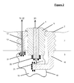
- This candle 1 is conventionally constituted a base 2, an electrical insulator 5, and a central electrode 4.
- the central electrode 4 is connected to means 23 allowing generation, to a predetermined instant, of an electric arc 17 between the central electrode 4 and a point on the base 2, for example a rod 16.
- a voltage source 22 ensures the polarization of the antenna 12 by compared to base 2 and cylinder head 7.
- a sleeve insulator 13 in alumina-based ceramic, ensures the electrical insulation of the antenna 12 with respect to the whole environment except the bedroom combustion 3, the measuring device 15, and the polarization means 22.
- the difference of potential generated by means 23 between the central electrode 4 and the base 2 reaches a peak very high absolute value (around ten thousand volts) during the short interval required to the establishment of the electric arc 17, then falls back to a more modest value (a few hundred absolute volts) where it stabilizes during the rest of the duration of arc 17.
- a peak very high absolute value around ten thousand volts
- a more modest value a few hundred absolute volts
- the antenna 12 Due to the existence of a difference of potential between the antenna 12 polarized by means 22 and the combustion gases 19, the antenna 12 therefore captures one of these two kinds of species; he an ionization current is thus established, the characteristics depend on the nature of the gases combustion and therefore the quality of combustion.
- the antenna 12 is according to the invention, polarized at a positive potential higher than those of base 2 and cylinder head 7, so as to capture the negatively charged species 21, which, appearing more mobile than charged species positively 20, are easier to collect and thus guarantee an excellent sensitivity of measured.
- the bias potential 26 can therefore be chosen to an arbitrary positive value, by example a few volts or a few dozen volts, to achieve the desired effect of capturing negatively charged ionic species from the start of combustion. It is even possible not to polarize the antenna 12 by an external source and the leave at floating potential.
- the low level of potential applied to antenna 12 therefore allows mounting particularly simple.
- the potential for polarization 22 of antenna 12 must be chosen greater than the potential of the central electrode 4 after the initiation peak of arc 17. This provision then ensures that the antenna 12 attracts negatively charged species 21 preferentially to the central electrode 4.
- the polarization potential 26 of the antenna 12 is therefore chosen at a positive value arbitrary about a few hundred volts, this which significantly complicates the assembly compared to the solution described in relation to Figure 4a since the required voltage level is high.
- the quality of the current measurement ionization is related to the potential difference between the antenna 12 and the combustion gases which are are polarized by the central electrode 4, therefore plus the return to 0 V of the electrode potential 4 is slow and the longer it is possible to extend in time the measurement of the ionization current without have to use a high bias potential for antenna 12, even not to polarize the antenna by an external source and leave it at floating potential.
- the arc 17 in the candle 1 takes place when the transistor 34, on receipt of the control signal 29, closes the primary circuit 27 of the coil, which generates a high voltage current in the secondary 28 of the coil.
- the command 29, consisting of a positive niche of voltage is received by a retarder 30 whose delay time is equal to the duration of the signal command 29 added to the desired duration of the arc 17.
- This delay means that immediately before the self-timer 30 transmits the control 29 to the field effect transistor 32, the primary circuit 27 of the coil is open, the resistance 33 having the effect of maintaining the terminals of transistor 32 at neighboring potentials.
- the capacity 31 has the effect of adding the potentials of the control signal 29 and of the primary 27 supply of the coil and bring the potential of the gate of transistor 32 to this value.
- the transistor short-circuits primary of the coil 27 having at its terminals a potential of the order of a volt, which generates a potential difference in the secondary of the coil 28 of about 100 volts, lower than that necessary for the establishment of arc 17, and again polarizes the central electrode 4 with a potential gradually evolving towards 0 V up to what all of the electrical energy present in the primary circuit be dissipated in the transistor 32, cf.
- Figures 6a and 6b are the effect of adding the potentials of the control signal 29 and of the primary 27 supply of the coil and bring the potential of the gate of transistor 32 to this value.
- the device object of the invention it is possible to measure the current ionization generated in a combustion chamber during the combustion of the fuel mixture by a antenna integrated in the spark plug, from the arrival of the flame on the antenna even in presence of the ignition electric arc.
- the present invention can apply regardless of the number of antennas used. It may indeed be preferable use multiple antennas to appreciate more precisely the course of combustion.
- the antenna (s) used for measure the ionization current may not be carried by the spark plug base, or the antennas being for example located directly through the cylinder head.
Abstract
Description
La présente invention concerne un dispositif de mesure du courant d'ionisation dans une chambre de combustion.The present invention relates to a device for measuring the ionization current in a room combustion.
Il est connu de caractériser la qualité des combustions survenant dans les chambres de combustion des moteurs à combustion interne par la mesure d'un courant dit d'ionisation. En effet, la cinétique chimique de la combustion d'un mélange carburé air-essence produit majoritairement des radicaux électriquement neutres. Elle produit également une faible quantité d'ions comme les ions OH-. Ces espèces ioniques engendrées par la combustion ont une durée de vie suffisante pour rendre conducteur les gaz de combustion. Grâce à des électrodes débouchant dans la chambre de combustion et maintenues à des potentiels électriques différents, il est donc possible d'observer un courant électrique dit d'ionisation circulant entre les électrodes.It is known to characterize the quality of the combustions occurring in the combustion chambers of internal combustion engines by measuring a so-called ionization current. In fact, the chemical kinetics of the combustion of a fuel-air-gasoline mixture mainly produces electrically neutral radicals. It also produces a small amount of ions such as OH - ions. These ionic species generated by combustion have a sufficient lifetime to make the combustion gases conductive. Thanks to electrodes opening into the combustion chamber and maintained at different electrical potentials, it is therefore possible to observe an electrical current called ionization flowing between the electrodes.
De tels dispositifs de détection du courant d'ionisation sont décrits dans les documents JP 129534/93 et JP 129796/93. Ces documents divulguent des modes de réalisation d'un détecteur, mais ne précisent pas de quelle manière la mesure doit être faite pour offrir la qualité la meilleure.Such current detection devices ionization are described in JP documents 129534/93 and JP 129796/93. These documents disclose embodiments of a detector, but do not not specify how the measurement should be made to offer the best quality.
La présente invention a donc pour objet un dispositif de mesure du courant d'ionisation qui améliore les performances des dispositifs connus à ce jour, en offrant une excellente sensibilité de mesure et limitant les perturbations engendrées par les étincelles d'allumage. The present invention therefore relates to a ionization current measuring device which improves the performance of known devices date, offering excellent sensitivity of measuring and limiting the disturbances caused by ignition sparks.
Le dispositif de mesure du courant d'ionisation dans une chambre de combustion de moteur à combustion interne à allumage commandé selon l'invention est du type comportant une bougie d'allumage présentant une électrode centrale reliée à des moyens d'alimentation électrique et insérée dans un culot par l'intermédiaire d'un isolateur, et au moins une antenne débouchant dans la chambre au voisinage de la bougie, cette antenne coopérant avec des moyens de mesure et des moyens de polarisation.The current measurement device ionization in a combustion chamber of internal combustion engine with positive ignition according to the invention is of the type comprising a candle with a central electrode connected to means of electrical supply and inserted in a pellet via an insulator, and at least one antenna opening into the room at neighborhood of the candle, this antenna cooperating with measurement means and polarization means.
Selon l'invention, le dispositif de mesure du courant d'ionisation dans une chambre de combustion est caractérisé en ce que les moyens de polarisation de l'antenne sont conformés pour polariser cette dernière à un potentiel électrique positif adapté, de manière à recueillir le courant engendré par les espèces ionisées négatives présentes dans la chambre de combustion et générées par la combustion du mélange carburé initiée par le déclenchement d'un arc électrique entre l'électrode centrale et le culot de la bougie.According to the invention, the measuring device of the ionization current in a combustion is characterized in that the means of antenna polarization are shaped to polarize the latter to an electrical potential positive adapted, so as to collect the current generated by negative ionized species present in the combustion chamber and generated by the combustion of the fuel mixture initiated by the triggering of an electric arc between the electrode central and the base of the candle.
Selon un premier mode de réalisation du dispositif de mesure du courant d'ionisation dans une chambre de combustion objet de l'invention, les moyens d'alimentation électrique de l'électrode centrale de la bougie sont conformés pour polariser négativement ladite électrode centrale.According to a first embodiment of the device for measuring the ionization current in a combustion chamber object of the invention, the means of electrical supply to the electrode candle center are shaped to polarize negatively said central electrode.
Selon une autre caractéristique de ce premier mode de réalisation du dispositif de mesure du courant d'ionisation dans une chambre de combustion objet de l'invention, les moyens de polarisation de l'antenne sont conformés pour polariser cette dernière à un potentiel électrique positif de quelques dizaines de volts.According to another characteristic of this first embodiment of the measuring device of the ionization current in a combustion object of the invention, the means of antenna polarization are shaped to polarize the latter to an electrical potential positive of a few tens of volts.
Selon un second mode de réalisation du dispositif de mesure du courant d'ionisation dans une chambre de combustion objet de l'invention, les moyens d'alimentation électrique de l'électrode centrale de la bougie sont conformés pour polariser positivement ladite électrode centrale.According to a second embodiment of the device for measuring the ionization current in a combustion chamber object of the invention, the means of electrical supply to the electrode candle center are shaped to polarize positively said central electrode.
Selon une autre caractéristique du dispositif de mesure du courant d'ionisation dans une chambre de combustion objet de l'invention, les moyens de polarisation de l'antenne sont conformés pour polariser l'antenne à un potentiel électrique positif sensiblement supérieur à celui sensiblement stable de l'électrode centrale de la bougie suivant le pic d'amorçage de l'arc électrique.According to another characteristic of the device for measuring the ionization current in a combustion chamber object of the invention, the antenna polarization means are conformed to polarize the antenna at an electrical potential positive significantly higher than that substantially stable spark plug center electrode next the ignition peak of the electric arc.
Selon une autre caractéristique du dispositif de mesure du courant d'ionisation dans une chambre de combustion objet de l'invention, les moyens d'alimentation électrique de l'électrode centrale de la bougie sont conformés pour continuer à polariser ladite électrode après la fin de l'arc électrique.According to another characteristic of the device for measuring the ionization current in a combustion chamber object of the invention, the means of electrical supply to the electrode candle center are shaped to continue polarizing said electrode after the end of the arc electric.
Selon une autre caractéristique du dispositif de mesure du courant d'ionisation dans une chambre de combustion objet de l'invention, les moyens d'alimentation électrique de l'électrode centrale de la bougie sont conformés pour contrôler la durée de l'arc électrique.According to another characteristic of the device for measuring the ionization current in a combustion chamber object of the invention, the means of electrical supply to the electrode central candle are shaped to control the duration of the electric arc.
On comprendra mieux les buts, aspects et
avantages de la présente invention, d'après la
description donnée ci-après de modes de réalisation
de l'invention, ces modes étant présentés à titre
d'exemples non limitatifs en se référant aux dessins
annexés, dans lesquels :
Conformément aux figures, seuls les éléments indispensables à la compréhension de l'invention ont été figurés. Par ailleurs, pour faciliter la lecture des dessins, les mêmes éléments portent les mêmes références d'une figure à l'autre.According to the figures, only the elements essential to understanding the invention have been figured. In addition, to facilitate reading drawings, the same elements have the same references from one figure to another.
En se reportant sur les figures 1 à 3, on
voit une bougie d'allumage 1 en position dans la
culasse 7 d'un moteur à combustion interne pour
déboucher dans une chambre de combustion 3.Referring to Figures 1 to 3, we
sees a
Cette bougie 1 est classiquement constituée
d'un culot 2, d'un isolateur électrique 5, et d'une
électrode centrale 4. L'électrode centrale 4 est
reliée à des moyens 23 permettant la génération, à
un instant prédéterminé, d'un arc électrique 17
entre l'électrode centrale 4 et un point du culot 2,
par exemple une tige 16.This
Une antenne 12, faite d'un matériau
conducteur de l'électricité, est implantée dans le
culot 2 et reliée à un appareillage de mesure 15 par
l'intermédiaire d'un câble 14. Une source de tension
22 assure la polarisation de l'antenne 12 par
rapport au culot 2 et à la culasse 7. Un manchon
isolant 13 en céramique à base d'alumine, assure
l'isolation électrique de l'antenne 12 par rapport à
tout l'environnement excepté donc la chambre de
combustion 3, l'appareillage de mesure 15, et les
moyens de polarisation 22.An
Au moment de l'allumage, la différence de
potentiel engendrée par les moyens 23 entre
l'électrode centrale 4 et le culot 2 atteint un pic
de valeur absolue très élevée (d'environ dix mille
volts) pendant le bref intervalle nécessaire à
l'établissement de l'arc électrique 17, puis retombe
à une valeur plus modeste (de quelques centaines de
volts en valeur absolue) où elle se stabilise
pendant le reste de la durée de l'arc 17. Lorsque
l'arc 17 disparaít la tension entre les bornes de la
bougie tend ensuite rapidement vers 0 V.At the time of ignition, the difference of
potential generated by
Après l'allumage, la combustion du mélange
carburé présent dans la chambre 3 se propage sur un
front de flamme 18 qui entoure une région de gaz
brûlés 19. Ceux-ci contiennent, au voisinage
immédiat du front de flamme 18, de nombreux produits
intermédiaires des réactions chimiques de
combustion, en particulier des espèces chargées
positivement 20 et des espèces chargées négativement
21.After ignition, the combustion of the mixture
fuel present in
Du fait de l'existence d'une différence de
potentiel entre l'antenne 12 polarisée par les
moyens 22 et les gaz de combustion 19, l'antenne 12
capte donc l'une de ces deux sortes d'espèces ; il
s'établit ainsi un courant d'ionisation dont les
caractéristiques dépendent de la nature des gaz de
combustion et donc de la qualité de la combustion.Due to the existence of a difference of
potential between the
L'antenne 12 est selon l'invention,
polarisée à un potentiel positif supérieur à ceux du
culot 2 et de la culasse 7, de façon à capter les
espèces chargées négativement 21, lesquelles,
apparaissant plus mobiles que les espèces chargées
positivement 20, sont plus aisées à recueillir et
garantissent ainsi une excellente sensibilité de
mesure.The
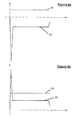
En se reportant à la figure 4a, on a
représenté les évolutions dans le temps de la
tension de polarisation 26 de l'antenne 12 et de la
tension 25 aux bornes des électrodes de la bougie 1
dans le cas où le circuit d'alimentation 23 de la
bougie 1 polarise l'électrode centrale 4
négativement vis-à-vis du culot 2 et de la culasse
7.Referring to Figure 4a, we have
represented the evolutions over time of the
Dans ce cas là, le simple fait que l'antenne
12 soit polarisée positivement suffit à attirer les
espèces chargées négativement 21 dés le contact de
l'antenne avec les gaz de combustion et tout au long
du déroulement de la combustion, puisque l'antenne
12 est le seul élément à être polarisée
positivement.In this case, the simple fact that the
Le potentiel de polarisation 26 peut donc
être choisi à une valeur positive arbitraire, par
exemple quelques volts ou quelques dizaines de
volts, pour obtenir l'effet désiré de capture des
espèces ioniques chargées négativement dès le début
de la combustion. Il est même envisageable de ne pas
polariser l'antenne 12 par une source externe et la
laisser au potentiel flottant.The
Le faible niveau de potentiel a appliqué à
l'antenne 12 permet donc des montages
particulièrement simples.The low level of potential applied to
En se reportant à la figure 4b, on a
représenté l'évolution d'une part de la tension de
polarisation 26 et d'autre part de la tension 25 aux
bornes des électrodes de la bougie 1 dans le cas où
le circuit d'alimentation 23 de la bougie 1 polarise
l'électrode centrale 4 positivement vis-à-vis du
culot 2 et de la culasse 7.Referring to Figure 4b, we have
represented the evolution on the one hand of the tension of
Dans ce cas là, pour attirer les espèces
chargées négativement 21 très tôt dans le
développement de la combustion c'est-à-dire avant
même la fin de l'arc 17, le potentiel de
polarisation 22 de l'antenne 12 doit être choisi
supérieur au potentiel de l'électrode centrale 4
après le pic d'amorçage de l'arc 17. Cette
disposition garantit alors que l'antenne 12 attire
les espèces chargées négativement 21
préférentiellement à l'électrode centrale 4.In this case, to attract cash
negatively charged 21 very early in the
development of combustion i.e. before
even the end of
Le potentiel de polarisation 26 de l'antenne
12 est donc alors choisi à une valeur positive
arbitraire d'environ quelques centaines de volts, ce
qui complexifie sensiblement le montage par rapport
à la solution décrite par rapport à la figure 4a
puisque le niveau de tension requis est élevé.The
En variante de réalisation et pour améliorer
encore la mesure du courant de polarisation, il est
apparu intéressant de limiter la durée de l'arc 17 à
la seule durée nécessaire à la bonne initiation de
combustion. En effet, tant que l'arc 17 existe entre
les électrodes de la bougie 1, la tension réelle
entre ces bornes n'est pas totalement stabilisée
après le pic d'amorçage et il peut survenir des pics
secondaires qui perturbent la mesure dans le cas où
l'électrode centrale 4 est polarisée positivement.
Pour ce faire, il suffit de commander la durée
d'allumage de façon adaptée.As an alternative embodiment and to improve
still measuring the bias current it's
appeared interesting to limit the duration of
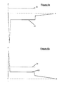
Selon une autre variante de réalisation et
pour améliorer également le dispositif de mesure du
courant de polarisation, il est apparu intéressant,
notamment dans le cas de la polarisation négative de
l'électrode centrale 1, de contrôler après la fin de
l'arc 17 l'évolution de la tension aux bornes des
électrodes de la bougie 1. According to another alternative embodiment and
to also improve the device for measuring the
bias current, it appeared interesting,
especially in the case of negative polarization of
the
En effet, la qualité de la mesure du courant
d'ionisation est liée à la différence de potentiel
entre l'antenne 12 et les gaz de combustion qui se
trouvent polarisés par l'électrode centrale 4, donc
plus le retour vers 0 V du potentiel de l'électrode
4 est lent et plus il est possible de prolonger dans
le temps la mesure du courant d'ionisation sans
avoir à utiliser un potentiel de polarisation élevé
pour l'antenne 12, voir même à ne pas polariser
l'antenne par une source externe et la laisser au
potentiel flottant.Indeed, the quality of the current measurement
ionization is related to the potential difference
between the
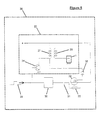
On a détaillé cette variante de réalisation
en se reportant à la figure 5. Sur cette figure on a
donc représenté un mode de réalisation des moyens 23
de génération d'un arc électrique d'allumage dans la
bougie 1 et des moyens 36 de maintien d'une certaine
polarisation de l'électrode centrale 4 après la fin
de l'arc 17.We have detailed this variant
referring to figure 5. In this figure we have
therefore represented an embodiment of the
L'arc 17 dans la bougie 1 a lieu lorsque le
transistor 34, à réception du signal de commande 29,
ferme le circuit primaire 27 de la bobine, ce qui
engendre un courant sous haute tension dans le
secondaire 28 de la bobine. Au même instant, la
commande 29, constituée d'un créneau positif de
tension, est reçue par un retardateur 30 dont le
temps de retard est égal à la durée du signal de
commande 29 ajoutée à la durée souhaitée de l'arc
17.The
La valeur de ce retard fait qu'immédiatement
avant que le retardateur 30 ne transmette la
commande 29 au transistor à effet de champ 32, le
circuit primaire 27 de la bobine est ouvert, la
résistance 33 ayant pour effet de maintenir les
bornes du transistor 32 à des potentiels voisins.
Lorsque le retardateur 30 transmet la commande 29,
le transistor 32, protégé par la diode 35, ferme le
circuit primaire 27 de la bobine.The value of this delay means that immediately
before the self-
La capacité 31 a pour effet d'ajouter les
potentiels du signal de commande 29 et de
l'alimentation du primaire 27 de la bobine et de
porter le potentiel de la grille du transistor 32 à
cette valeur. Le transistor court-circuite le
primaire de la bobine 27 présentant à ses bornes un
potentiel de l'ordre du volt, ce qui engendre une
différence de potentiel dans le secondaire de la
bobine 28 d'environ 100 volts, inférieure à celle
nécessaire à l'établissement de l'arc 17, et
polarise de nouveau l'électrode centrale 4 avec un
potentiel évoluant progressivement vers 0 V jusqu'à
ce que toute l'énergie électrique présente dans le
circuit primaire soit dissipée dans le transistor
32, cf. les figures 6a et 6b.The
Conformément au dispositif objet de l'invention, il est possible de mesurer le courant d'ionisation généré dans une chambre de combustion lors de la combustion du mélange carburé par une antenne intégrée à la bougie d'allumage, dès l'arrivée de la flamme sur l'antenne même en présence de l'arc électrique d'allumage.In accordance with the device object of the invention it is possible to measure the current ionization generated in a combustion chamber during the combustion of the fuel mixture by a antenna integrated in the spark plug, from the arrival of the flame on the antenna even in presence of the ignition electric arc.
Bien entendu, l'invention n'est nullement limitée au mode de réalisation décrit et illustré qui n'a été donné qu'à titre d'exemple.Of course, the invention is by no means limited to the embodiment described and illustrated which was only given as an example.
Au contraire, l'invention comprend tous les équivalents techniques des moyens décrits ainsi que leurs combinaisons si celles-ci sont effectuées suivant son esprit. On the contrary, the invention includes all technical equivalents of the means described as well as their combinations if these are performed following his spirit.
Ainsi, la présente invention peut s'appliquer quel que soit le nombre d'antennes utilisées. Il peut être, en effet, préférable d'utiliser plusieurs antennes pour apprécier plus précisement le déroulement de la combustion.Thus, the present invention can apply regardless of the number of antennas used. It may indeed be preferable use multiple antennas to appreciate more precisely the course of combustion.
Ainsi, la ou les antennes utilisées pour mesurer le courant d'ionisation peuvent ne pas être portées par le culot de la bougie d'allumage, la ou les antennes étant par exemple implantées directement à travers la culasse.Thus, the antenna (s) used for measure the ionization current may not be carried by the spark plug base, or the antennas being for example located directly through the cylinder head.
Claims (8)
Applications Claiming Priority (2)
| Application Number | Priority Date | Filing Date | Title |
|---|---|---|---|
| FR9716128A FR2772922B1 (en) | 1997-12-19 | 1997-12-19 | DEVICE FOR MEASURING THE IONIZATION CURRENT IN A COMBUSTION CHAMBER |
| FR9716128 | 1997-12-19 |
Publications (2)
| Publication Number | Publication Date |
|---|---|
| EP0926338A1 true EP0926338A1 (en) | 1999-06-30 |
| EP0926338B1 EP0926338B1 (en) | 2003-08-13 |
Family
ID=9514818
Family Applications (1)
| Application Number | Title | Priority Date | Filing Date |
|---|---|---|---|
| EP19980403207 Expired - Lifetime EP0926338B1 (en) | 1997-12-19 | 1998-12-18 | Device for measuring the ionisation current in a combustion chamber |
Country Status (3)
| Country | Link |
|---|---|
| EP (1) | EP0926338B1 (en) |
| DE (1) | DE69817134T2 (en) |
| FR (1) | FR2772922B1 (en) |
Cited By (2)
| Publication number | Priority date | Publication date | Assignee | Title |
|---|---|---|---|---|
| EP2732142A4 (en) * | 2011-07-15 | 2015-03-04 | Univ Wayne State | Simultaneous ion sensing and gas sampling in combustion engine cylinders and other combustion systems |
| WO2018098278A1 (en) | 2016-11-22 | 2018-05-31 | Ic Llc | Spark plug combustion ionization sensor |
Citations (3)
| Publication number | Priority date | Publication date | Assignee | Title |
|---|---|---|---|---|
| US5180983A (en) * | 1990-09-27 | 1993-01-19 | Mitsubishi Denki K.K. | Ignition plug for an internal combustion engine provided with an ionization current detector electrode |
| US5271268A (en) * | 1990-11-26 | 1993-12-21 | Mitsubishi Denki Kabushiki Kaisha | Ionic current sensing apparatus |
| EP0627622A2 (en) * | 1993-05-31 | 1994-12-07 | Ngk Spark Plug Co., Ltd | An ion current detector device for use in an internal combustion engine |
-
1997
- 1997-12-19 FR FR9716128A patent/FR2772922B1/en not_active Expired - Fee Related
-
1998
- 1998-12-18 EP EP19980403207 patent/EP0926338B1/en not_active Expired - Lifetime
- 1998-12-18 DE DE69817134T patent/DE69817134T2/en not_active Expired - Lifetime
Patent Citations (3)
| Publication number | Priority date | Publication date | Assignee | Title |
|---|---|---|---|---|
| US5180983A (en) * | 1990-09-27 | 1993-01-19 | Mitsubishi Denki K.K. | Ignition plug for an internal combustion engine provided with an ionization current detector electrode |
| US5271268A (en) * | 1990-11-26 | 1993-12-21 | Mitsubishi Denki Kabushiki Kaisha | Ionic current sensing apparatus |
| EP0627622A2 (en) * | 1993-05-31 | 1994-12-07 | Ngk Spark Plug Co., Ltd | An ion current detector device for use in an internal combustion engine |
Cited By (4)
| Publication number | Priority date | Publication date | Assignee | Title |
|---|---|---|---|---|
| EP2732142A4 (en) * | 2011-07-15 | 2015-03-04 | Univ Wayne State | Simultaneous ion sensing and gas sampling in combustion engine cylinders and other combustion systems |
| US9945812B2 (en) | 2011-07-15 | 2018-04-17 | Wayne State University | Simultaneous ion sensing and gas sampling in combustion engine cylinders and other combustion systems |
| WO2018098278A1 (en) | 2016-11-22 | 2018-05-31 | Ic Llc | Spark plug combustion ionization sensor |
| EP3545187A4 (en) * | 2016-11-22 | 2020-07-22 | Ic Llc | Spark plug combustion ionization sensor |
Also Published As
| Publication number | Publication date |
|---|---|
| EP0926338B1 (en) | 2003-08-13 |
| DE69817134T2 (en) | 2004-06-09 |
| FR2772922B1 (en) | 2000-03-03 |
| DE69817134D1 (en) | 2003-09-18 |
| FR2772922A1 (en) | 1999-06-25 |
Similar Documents
| Publication | Publication Date | Title |
|---|---|---|
| EP2205858B1 (en) | Device for measuring the ionization current in a radiofrequency ignition system for an internal combustion engine | |
| FR2667362A1 (en) | DIRECT IGNITION SYSTEM FOR INTERNAL COMBUSTION ENGINE AND COIL ASSEMBLY. | |
| FR2910730A1 (en) | PLASMA IGNITION SYSTEM | |
| EP2002117B1 (en) | Method for measuring an ionization current of a spark plug of the type with resonant structure, and corresponding device | |
| FR2459563A1 (en) | PLASMA JET IGNITION CANDLE | |
| CA1118833A (en) | Electric circuit to ignite a detonator | |
| FR2787834A1 (en) | COMBUSTION STATE DETECTION DEVICE FOR COMBUSTION ENGINE | |
| FR2575871A1 (en) | INTERMITTENT IMPULSIVE CROWN CONDEMBER | |
| FR2864172A1 (en) | DOUBLE-STAGE IONIZATION DETECTION CIRCUIT | |
| FR2878086A1 (en) | PLASMA RADIOFREQUENCY CANDLE | |
| FR2777607A1 (en) | CONTROLLED ENERGY IGNITION SYSTEM FOR AN INTERNAL COMBUSTION ENGINE | |
| WO2010029238A1 (en) | Device for measuring the ionization current in a radiofrequency ignition system for an internal combustion engine | |
| EP0926338B1 (en) | Device for measuring the ionisation current in a combustion chamber | |
| EP0260177B1 (en) | Device for detecting irregular combustion fluctuations in a cylinder of an internal-combustion engine with controlled ignition | |
| FR2930092A1 (en) | CIRCUIT AND METHOD FOR CONTROLLING PENCIL CANDLES TO PROTECT THEM FROM POLARITY ERROR. | |
| US20130125558A1 (en) | Preheating a spark plug | |
| FR2827916A1 (en) | METHOD FOR CONTROLLING THE IGNITION PARAMETERS OF A SPARK PLUG FOR AN INTERNAL COMBUSTION ENGINE AND IGNITION DEVICE USING SUCH A METHOD | |
| FR2811749A1 (en) | SECURE HIGH-ENERGY ELECTRO-PYROTECHNIC INITIATOR | |
| WO2007066031A1 (en) | Method and device for providing diagnostics for an internal combustion engine ignition coil | |
| EP0268528B1 (en) | Ignition device for an internal-combustion engine | |
| FR3049780A1 (en) | METHOD AND DEVICE FOR REGENERATING A SEMICONDUCTOR IGNITION CANDLE | |
| FR2946190A1 (en) | METHOD FOR DETECTING THE TYPE OF SPARK GENERATED BY A RADIOFREQUENCY IGNITION CANDLE COIL AND CORRESPONDING DEVICE | |
| EP0866917A2 (en) | Internal combustion engine ignition system monitoring device | |
| EP0199616B1 (en) | Checking device for the ignition of a pyrotechnic charge | |
| EP1628377A1 (en) | Protection device for electrical installations against overvoltages comprising a spark gap with a triggering circuit |
Legal Events
| Date | Code | Title | Description |
|---|---|---|---|
| PUAI | Public reference made under article 153(3) epc to a published international application that has entered the european phase |
Free format text: ORIGINAL CODE: 0009012 |
|
| AK | Designated contracting states |
Kind code of ref document: A1 Designated state(s): DE ES GB IT |
|
| AX | Request for extension of the european patent |
Free format text: AL;LT;LV;MK;RO;SI |
|
| 17P | Request for examination filed |
Effective date: 19991129 |
|
| AKX | Designation fees paid |
Free format text: DE ES GB IT |
|
| GRAG | Despatch of communication of intention to grant |
Free format text: ORIGINAL CODE: EPIDOS AGRA |
|
| 17Q | First examination report despatched |
Effective date: 20020624 |
|
| RAP1 | Party data changed (applicant data changed or rights of an application transferred) |
Owner name: RENAULT S.A.S. |
|
| GRAG | Despatch of communication of intention to grant |
Free format text: ORIGINAL CODE: EPIDOS AGRA |
|
| GRAH | Despatch of communication of intention to grant a patent |
Free format text: ORIGINAL CODE: EPIDOS IGRA |
|
| GRAH | Despatch of communication of intention to grant a patent |
Free format text: ORIGINAL CODE: EPIDOS IGRA |
|
| GRAA | (expected) grant |
Free format text: ORIGINAL CODE: 0009210 |
|
| AK | Designated contracting states |
Designated state(s): DE ES GB IT |
|
| PG25 | Lapsed in a contracting state [announced via postgrant information from national office to epo] |
Ref country code: IT Free format text: LAPSE BECAUSE OF FAILURE TO SUBMIT A TRANSLATION OF THE DESCRIPTION OR TO PAY THE FEE WITHIN THE PRESCRIBED TIME-LIMIT;WARNING: LAPSES OF ITALIAN PATENTS WITH EFFECTIVE DATE BEFORE 2007 MAY HAVE OCCURRED AT ANY TIME BEFORE 2007. THE CORRECT EFFECTIVE DATE MAY BE DIFFERENT FROM THE ONE RECORDED. Effective date: 20030813 Ref country code: GB Free format text: LAPSE BECAUSE OF FAILURE TO SUBMIT A TRANSLATION OF THE DESCRIPTION OR TO PAY THE FEE WITHIN THE PRESCRIBED TIME-LIMIT Effective date: 20030813 |
|
| REG | Reference to a national code |
Ref country code: GB Ref legal event code: FG4D Free format text: NOT ENGLISH |
|
| REF | Corresponds to: |
Ref document number: 69817134 Country of ref document: DE Date of ref document: 20030918 Kind code of ref document: P |
|
| PG25 | Lapsed in a contracting state [announced via postgrant information from national office to epo] |
Ref country code: ES Free format text: LAPSE BECAUSE OF FAILURE TO SUBMIT A TRANSLATION OF THE DESCRIPTION OR TO PAY THE FEE WITHIN THE PRESCRIBED TIME-LIMIT Effective date: 20031124 |
|
| GBV | Gb: ep patent (uk) treated as always having been void in accordance with gb section 77(7)/1977 [no translation filed] |
Effective date: 20030813 |
|
| PLBE | No opposition filed within time limit |
Free format text: ORIGINAL CODE: 0009261 |
|
| STAA | Information on the status of an ep patent application or granted ep patent |
Free format text: STATUS: NO OPPOSITION FILED WITHIN TIME LIMIT |
|
| 26N | No opposition filed |
Effective date: 20040514 |
|
| PGFP | Annual fee paid to national office [announced via postgrant information from national office to epo] |
Ref country code: DE Payment date: 20141211 Year of fee payment: 17 |
|
| REG | Reference to a national code |
Ref country code: DE Ref legal event code: R119 Ref document number: 69817134 Country of ref document: DE |
|
| PG25 | Lapsed in a contracting state [announced via postgrant information from national office to epo] |
Ref country code: DE Free format text: LAPSE BECAUSE OF NON-PAYMENT OF DUE FEES Effective date: 20160701 |