EP0925800B1 - Resuscitator device with self closing valve - Google Patents
Resuscitator device with self closing valve Download PDFInfo
- Publication number
- EP0925800B1 EP0925800B1 EP98310363A EP98310363A EP0925800B1 EP 0925800 B1 EP0925800 B1 EP 0925800B1 EP 98310363 A EP98310363 A EP 98310363A EP 98310363 A EP98310363 A EP 98310363A EP 0925800 B1 EP0925800 B1 EP 0925800B1
- Authority
- EP
- European Patent Office
- Prior art keywords
- disc
- valve
- housing
- air
- valve seat
- Prior art date
- Legal status (The legal status is an assumption and is not a legal conclusion. Google has not performed a legal analysis and makes no representation as to the accuracy of the status listed.)
- Expired - Lifetime
Links
- 230000000295 complement effect Effects 0.000 claims description 4
- 238000007599 discharging Methods 0.000 claims description 4
- 239000012530 fluid Substances 0.000 description 9
- 230000001681 protective effect Effects 0.000 description 9
- 230000004888 barrier function Effects 0.000 description 4
- 238000000034 method Methods 0.000 description 4
- 230000004044 response Effects 0.000 description 4
- 230000000903 blocking effect Effects 0.000 description 3
- 239000012535 impurity Substances 0.000 description 3
- 210000004072 lung Anatomy 0.000 description 3
- 230000002093 peripheral effect Effects 0.000 description 3
- 230000029058 respiratory gaseous exchange Effects 0.000 description 3
- 238000005452 bending Methods 0.000 description 2
- 230000000747 cardiac effect Effects 0.000 description 2
- 230000002685 pulmonary effect Effects 0.000 description 2
- 239000000356 contaminant Substances 0.000 description 1
- 239000000463 material Substances 0.000 description 1
- 238000012986 modification Methods 0.000 description 1
- 230000004048 modification Effects 0.000 description 1
- 230000008569 process Effects 0.000 description 1
Images



Classifications
-
- A—HUMAN NECESSITIES
- A61—MEDICAL OR VETERINARY SCIENCE; HYGIENE
- A61M—DEVICES FOR INTRODUCING MEDIA INTO, OR ONTO, THE BODY; DEVICES FOR TRANSDUCING BODY MEDIA OR FOR TAKING MEDIA FROM THE BODY; DEVICES FOR PRODUCING OR ENDING SLEEP OR STUPOR
- A61M16/00—Devices for influencing the respiratory system of patients by gas treatment, e.g. ventilators; Tracheal tubes
- A61M16/0048—Mouth-to-mouth respiration
-
- A—HUMAN NECESSITIES
- A61—MEDICAL OR VETERINARY SCIENCE; HYGIENE
- A61M—DEVICES FOR INTRODUCING MEDIA INTO, OR ONTO, THE BODY; DEVICES FOR TRANSDUCING BODY MEDIA OR FOR TAKING MEDIA FROM THE BODY; DEVICES FOR PRODUCING OR ENDING SLEEP OR STUPOR
- A61M16/00—Devices for influencing the respiratory system of patients by gas treatment, e.g. ventilators; Tracheal tubes
- A61M16/10—Preparation of respiratory gases or vapours
- A61M16/105—Filters
- A61M16/106—Filters in a path
- A61M16/107—Filters in a path in the inspiratory path
Definitions
- This invention relates generally to devices for providing mouth-to-mouth resuscitation; and more specifically relates to devices having a physical barrier between the mouth of a rescuer and the mouth of the victim. Still more particularly, the invention relates to devices having a one way, self closing valve for transferring air under pressure from a rescuer to a victim, and blocking any reverse flow of fluid from the victim to the rescuer.
- Mouth-to-mouth resuscitation is a first aid technique and a preferred method for reviving a non-breathing victim when life or death may be determined from actions taken within a period of seconds, to rapidly deliver large volumes of exhaled air under pressure to inflate the lungs and reactivate the normal breathing process.
- the technique most commonly used in this regard is referred to as cardiac, pulmonary resuscitation ("C.P.R.”).
- Resuscitator devices to provide a physical barrier between the rescuer and victim requiring mouth-to-mouth resuscitation are widely used today and accepted. Moreover, these resuscitator devices are frequently included in first aid kits or stored at locations where emergency medical supplies are accessed. Often these resuscitator devices are carried on the person of parties trained in C.P.R. and would be called upon to provide C.P.R. or the like during emergency situations, such as ER doctors, paramedics, etc.
- U.S. Patent No. 4,819,628 (1989), Eisenberg et al, entitled “Mouth-to-Mouth Resuscitator Device,” discloses a resuscitator device having a physical barrier between the mouth of the rescuer and the mouth of the victim.
- the device comprises a flexible sheet having a mouth opening formed in the sheet; and a protective tube bonded around the periphery of the mouth opening and extending downward therefrom.
- a self closing one way valve is positioned in the tube and included a flexible sleeve having an open air inlet adjacent the mouth opening and an air outlet adjacent the output end of the tube; and a spring strip attached to the sleeve near the air outlet for securely closing the air outlet.
- the rescuer exhales air under pressure into the air inlet and the forced air entering the valve spreads the sleeve walls apart and overcomes the force of the spring strip for opening the valve and discharging the exhaled deep breath into the mouth of the victim.
- the tube containing the valve protects the valve and directs the forced air into the lungs of the victim.
- the protective tube of the resuscitator device have a smaller length than the length of such tube presently in use. If a victim were a child or a person having a more diminutive mouth structure, a smaller protective tube would be more suitable for use and less likely to injure or damage the inside mouth structure of the victim.
- the one way valve for the resuscitator device would be required to operate within a more confined area.
- the subject invention provides a mouth-to-mouth resuscitator device utilizing a valve arrangement capable of effectively operating within a smaller protective tube configuration than the longer length rigid tubes prevalent in use at the present time.
- U.S. Patent No. 5,355,877 describes a resuscitation device comprising an upper and lower casing separated by a flexible diaphragm.
- the diaphragm is held against the bottom of the upper casing by a pair of struts on the lower casing to form a seal between the upper and lower casings.
- the diaphragm bends at the portions not held by the struts and the air is free to pass into the lower casing.
- the diaphragm returns to its normally closed position, thus acting as a self-closing valve.
- a mouth-to-mouth resuscitator device including a self-closing one way valve effectively operable within a protective tube having a length substantially smaller than the length of the valve protective tube generally used for mouth-to-mouth resuscitator devices.
- Another object is to provide a resuscitator device for transferring exhaled air under pressure from a rescuer to a victim and blocking back flow of fluids from the victim to the rescuer.
- Another object is to provide a mouth-to-mouth resuscitator device having component parts that are easily assembled together.
- Another object is to prevent impurities from being transferred from the rescuer to the patient.
- the present invention provides a device for a rescuer to resuscitate a victim comprising a hollow housing having an input end for inserting forced air into the housing and an output end or outer side for discharging said forced air to resuscitate the victim; a valve disc having an air open position and an air closed position; and a valve seat positioned in said housing between said ends, said valve seat including an opening, and the valve disc permits flow of said forced air from the input end of the housing through the opening of the seat to the output end in the air open position and closes the opening of the seat in the air closed position; characterised in that the device further comprises a plate rigidly secured to the inside of the housing between the output end of the housing and the valve disc, with one end of the plate extending substantially across the valve disc; and attachment means positioned on the outer side of the disk for securing said end of the plate to the disc to divide the disc into a pair of moveable portions.
- the resuscitator device of this invention provides a physical shield between a rescuer and a victim or patient requiring mouth-to-mouth resuscitation.
- the device comprises a housing having a rescuer input end in which the rescuer exhales a deep breath under pressure and a victim output end for discharging the forced air into the mouth and lungs of the victim.
- a self closing, one way valve is secured in the housing and is normally in a closed-condition.
- the valve revolves or bends outward toward the victim to open the valve in response to said forced air, and thereby transferring the forced air from the input end to the output end.
- the valve resiliently revolves inward toward the rescuer air input end to return to the closed-condition, when said forced air has dissipated or is removed.
- the valve when in the closed-condition prevents reverse flow of fluids from the victim to the rescuer.
- the valve comprises a flexible oval shaped disc having opposite free ends.
- the disc is secured in the housing to divide into a pair of flaps; one flap extending from one free end to the longitudinal center of the disc and the other flap extending from the other free end to the longitudinal center of the disc.
- the flaps of the disc are bendable from a closed position along a lateral line passing through the longitudinal center of the disc, to open the valve and transfer the forced air to the victim output end.
- the flaps of the valve When the flaps of the valve are in the closed positions, the valve is closed to block passage of fluids through the device in the reverse direction from the victim air output end toward the rescuer air input end.
- the flaps function as a pair of lever arms, which revolve outward in opposite directions away from the input end to open the valve in response to the forced air pressure generated by the rescuer.
- the flaps resiliently bend or revolve inward in opposite directions to their closed positions when the forced air has dissipated.
- a plate is mounted in the housing so that an edge thereof supports the disc along a lateral line perpendicular to the longitudinal center line of the disc, to cause the bending of the disc into the pair of flaps.
- the plate includes a pair of opposed sides, whereby one said flap bends outwardly in one direction toward one side of the plate and the other flap bends outwardly in the opposite direction toward the other side of the plate. Therefore, the plate in cooperation with the valve disc functions as a fulcrum or hinge, to divide the disc into the pair of flaps that fold or bend outward on opposite sides of the plate, to open the valve and transfer the forced exhaled air from the rescuer to the victim air output end. When the disc (or flaps) is closed it blocks the fluid passageway through the device in the reverse direction, which may occur if the victim exhales thereby protecting the rescuer from contact with the victim's fluids.
- the resuscitator device further includes a valve seat encircling a hole and has a concave shape.
- the valve disc has a convex shape complementary to the concave shape of the seat and rests on the seat to close the hole, when the device is in the closed-condition.
- the valve seat contacts the periphery of the valve disc and blocks movement of the disc from the closed-condition to an open-condition when fluids back flow from the output end to the input end.
- valve disc is positioned in the air flow passageway, whereby reverse fluid flow forces the periphery of the disc against the valve seat to maintain the valve closed.
- valve seat and the valve disc cooperate for more securely closing the valve disc in response to the back flow of fluid from the output end toward the input end.
- the valve disc normally has a flat configuration (prior to being assembled in the device).
- the valve disc is stressed when shaped into a configuration other than flat.
- the valve disc is stressed in the convex shape to firmly contact the valve seat, when the valve is in the closed-condition. This is due to the concave valve seat blocking the valve disc from achieving a flat shape.
- a pair of spaced apart guide rods are formed on the outer side of the valve disc and extend laterally across the disc at the substantial center thereof. The inner edge of the plate is received in the space between the guide rods to easily and properly position the valve disc inside the resuscitator device when assembling the various parts of the device.
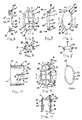
- the reference numeral 10 indicates generally a resuscitator device for use as a physical barrier between a rescuer and a victim or patient when the rescuer is resuscitating a victim or patient.
- the device 10 is particularly suitable when engaging in Cardiac Pulmonary Resuscitation ("C.P.R.”) or in other situations when the victim is unable or has extreme difficulty in breathing.
- C.P.R. Cardiac Pulmonary Resuscitation
- the resuscitator device 10 includes a flexible face shield 12 and a tubular assembly indicated generally by the reference numeral 14 which extends centrally through an opening 15 in the shield 12 and is sealed adjacent and around the opening 15.
- the tubular assembly 14 includes a rescuer section 16 and a valve section 17 secured together.
- Air exhaled by the rescuer under pressure is applied at the inner or rescuer end 18 of the rescuer section 16 (Fig. 17).
- the forced air is transmitted through the tubular assembly 14; and finally discharged into the mouth of the victim via the outer or patient end 19 of the valve section 17 of the device 10.
- the face shield 12 is shown having a substantially square shape, although various other shapes or configurations may be used.
- the opening 15 is shown having an elliptical shape and is centrally formed through the shield 12.
- the shield 12 includes a rescuer side 22 and a victim or patient side 24.
- the rescuer section 16 includes an oval shaped, hollow support cap 26 (Figs. 2 thru 5) having an oval shaped sidewall 27 extending between an open outer or bottom end 28 and an open inner or top end 30, as viewed in Figure 2.
- An annular flange or brim 32 (Figs. 4, 5 and 17) circumscribes the inner end 30 of the cap 26.
- the side wall 27 of the cap 26 is dimensioned to pass through the opening 15 in the face shield 12, so that the outer surface 34 of the flange 32 abuts the rescuer's side 22 of the face shield 12 bordering the opening 15 and is sealed thereto (Fig. 12).
- the outer end 28 of the cap 26 includes an oval flat outer edge 35 surrounding a protective grading or screen 36.
- the screen 36 comprises a longitudinal rib 38 intersecting a pair of spaced apart lateral ribs 39.
- An oval shaped filter pad 42 having an outer side 44 and an inner side 46 (Figs. 2 and 17) is supported on the outer edge 35 of the cap 26.
- the inner side 46 of the pad 42 is opposed to the screen 36 of the cap 26.
- the filter pad 42 prevents impurities from being transferred through the device 10 from the rescuer to the patient, if such impurities are not sufficiently blocked by the screen 36.
- a valve support indicated generally by the reference numeral 48 (Figs. 6, 7, 8. 13 and 14) supports a valve disc 50 (Fig. 2).
- the valve support 48 includes ar opening 51 extending from the inward end 52(Fig. 6a) to the outward end 54 of the valve support 48.
- the inward end 52 of the valve support 48 includes an inner, oval edge 56 having a flat surface (Fig. 6a and 7).
- the filter pad 42 is sandwiched between the inner edge 56 of the valve support 48 and the outer or bottom edge 35 of the cap 26 (Fig. 12), and may be secured to either or both edges 35,56.
- the outward end 54 of the valve support 48 includes a valve seat 57 having an oval, continuous outer edge 58 forming a concave shape.
- the oval outer edge 58 comprises a "U" shaped curved segment 59 integrally formed to an inverted “U” shaped curved segment 6C, and forming a pair of opposed depressions or troughs 62,63 at the longitudinal center of the oval outer edge 58.
- the U shaped segment 59 includes an apex 64; and similarly, the inverted U shaped segment 60 includes an apex 65.
- the longitudinal length of the outer edge 58 is the distance between apex 64 and apex 65.
- the apex 64 and the apex 65 are opposed to each other; and are the outermost points on the valve seat 57.
- the depressions 62,63 are positioned substantially midway between the apex 64 and the apex 65 and are laterally opposed to each other.
- the oval edge 58 curves outward (or upward) from the depression 62 to apex 65; curves inward (or downward) from apex 65 to the other depression 63; and curves outward (or downward) to apex 64.
- the apex 64 and apex 65 are the outermost points of the valve support 48.
- the valve disc 50 (Fig. 2 and 12) has an inner side 66 and an outer side 67.
- the disc 50 is flexible and pliable and may be formed from a suitable plastic material which is impermeable to air flow.
- the disc 50 normally when unrestrained has a flat configuration, as shown in Figures 2,18 and 19.
- the disc 50 is stressed when its shape deviates from the normal flat shape.
- the valve disc 50 is resiliently urged toward the flat shape, when, for example, an external force bending the disc 50 is removed. Hence, the valve disc 50 is stressed when seated on the concave surface 58 of the valve seat 57.
- the valve disc 50 is formed to a convex shape or configuration 68 complementary to the concave surface 58 of the valve seat 57, as shown in Figure 12.
- the convex shape 68 of the valve disc 50 is stressed to cause firm contact with the concave surface 59 of the valve seat 57.
- the resilient force of the valve disc 50 urges the disc 50 toward an unachievable flat shape due to being blocked by the concave surface 59 of the valve seat 57.
- valve seat 57 block the valve disc 50 from resiliently moving from the convex shape to its normal flat configuration such as shown prior to assembly of the parts in Figures 2 and 18.
- the valve support 48 and the valve disc 50 are secured inside a hollow tubular housing 70 (Figs. 9,10 and 11).
- the housing 70 has an oval or elliptical cross section, taken on the plane of the line perpendicular to the vertical or longitudinal axis of the housing.
- the housing 70 comprises an oval inlet end 72 and an oval outlet end 73.
- the outlet end 73 also includes a protective grading or screen 74 (Fig. 9).
- a plate 76 is centrally positioned inside the housing 70 and extends laterally through the longitudinal center of the housing 70.
- the plate 76 has substantially a square shape and includes an outer edge 78, an inner edge 79; and opposed side edges 80, 81.
- a pair of rectangular posts 83,84 are secured to the inside wall 85 of the housing 70 in an opposed relationship.
- the side edges 80,81 of plate 76 are fused or otherwise attached respectively to posts 83 and 84 (Figs. 11 and 18). Hence, the plate 76 is rigidly positioned inside the housing 70.
- the screen 74 at the outlet end 73 of the housing 70 includes a longitudinal bar 88 extending centrally along the longitudinal axis of the housing 70, between the vertex 90 of arc 91 and the vertex 92 of the opposite arc 93 of the oval outlet end 73 of the housing 70.
- the outer edge 78 of the plate 76 extends laterally at the center of the housing between opposed inside surfaces of the housing at the outlet end 73. Bars 94, 95 are equally spaced from the outer edge 78 of the plate 76 and extend laterally between opposed inside surfaces of the housing 70.
- the longitudinal bar 88 intersects the lateral bars 94,95 and the outer edge 78 of the plate 76.
- the screen 94 comprises the longitudinal bar 88, lateral bars 94,95 and the outer edge 78 of the plate 76, to block back flow of foreign matter and contaminants into the device 10 from the patient.
- An oval lip 98 extends around the inlet end 72 of the housing 70.
- the lip 98 is sealed to the patient side 24 of the face shield 12 around the opening 15.
- the valve disc 50 has an oval shape having opposed free ends 104, 106 equally spaced from the lateral center portion 108 of the disc 50. Operatively, the valve disc is restrained at the lateral center portion 108 to divide the disc valve 50 into a pair of movable flaps 110, 112.
- the lateral center portion 108 of the valve disc 50 is sandwiched between the inner edge 79 of the plate 76 and the surfaces defining the depressions 62,63 in the valve seat, so that the center portion 108 is in a fixed position.
- the flaps 110, 112 bend outward and toward each other to permit air transfer to the victim.
- the inner edge 79 of the plate 76 acts as a fulcrum: and flap 110 bends outward and toward side 114 of plate 76 and flap 112 bends outward and toward the opposite side 116 of plate 76.
- the outer edge 79 of the plate 76 is attached to the longitudinal bar 88 of the screen 74.
- the valve disc 50 is dimensioned to be positioned in the housing, so that the lateral center portion 108 on the outer side 67 of disc 50 is opposed to the inner edge 79 of the plate 76 and the lateral center portion 108 on the inner side 66 of disc 50 is opposed to the surfaces defining the depressions 62,63.
- a pair of spaced apart guide rods 122 and 124 are formed on the outer side 67 of the valve disc 50 and extend laterally across the disc at the substantial center thereof.
- the inner edge 79 of the plate 76 press fits inside the elongated space 125 between the guide rods 122, 124.
- the valve disc 50 is easily positioned inside the resuscitator device 10 at the proper location.
- the attachment of the disc 50 to the plate 76 maintains the lateral center portion 108 of the disc 50 fixidly positioned inside the housing.
- the guide rods 122, 124 are spaced from the peripheral edges of the valve disc, so that the defining surfaces of the depressions 62, 63 may easily position on the valve disc 50.
- the filter pad 42 is sealed between the outer end 28 of cap 26 and the inner end 52 of the valve support 48.
- the assembled cap 26 and valve support 48 are force fitted inside the housing, after the valve disc 50 is positioned in the housing.
- the lateral center portion 108 of the valve disc rests inside the depressions 62,63 of the valve support. Therefore, the center portion 108 of the valve disc 50 is restrained by the plate 76 and the valve seat 57, and functions as a hinge.
- the mouth of the victim Prior to using the device 10, the mouth of the victim is cleared of any obstructions.
- the housing 70 is placed in the mouth of the victim.
- the rescuer exhales air under pressure into the resuscitator device 10.
- the forced air passes through the rescuer or inner end 18 and through the filter pad 42 and into the valve section 17.
- the valve disc 50 is normally in a closed position.
- the plate 76 is rigidly secured inside the valve housing 70 to support the valve disc 50 and functions as a hinge for dividing the disc into flaps 110, 112.
- Flap 110 pivots or bends outward in a counter clockwise direction away from the input end 25 and toward one side of the plate 76 and the other flap 112 pivots or bends outward in the clockwise direction, away from the input end 18 and toward the other side of plate 76, in response to the forced air applied at the air input end 18 by the rescuer.
- the forced air rushes past the valve flaps 110, 112 to the patient output end 19 for discharge into the mouth of the patient. After the forced air exhaled by the rescuer has dissipated, the flaps 110, 112 self close to return to their closed-positions.
- the surfaces defining the opposed depressions 62,63 in the valve seat 57 clamp to the peripheral ends of the lateral center portion 108 (Fig. 22).
- the plate 76 abuts the outer side of the valve disc 50 and the defining surfaces of the depressions 62,63 abut the inner side 66 of the valve disc 50.
- the peripheral ends of the lateral center portion 18 are sandwiched between the inner edge 79 of the plate 76 and the defining surface of the corresponding depressions 62,63.
- the protruding apexes 59,60 push the free ends 104,106 of the valve disc 50 to form the convex shape for the valve disc 50.
- the plate 76 prevents any further outward movement of the valve support 48.
- the apexes 59,60 are in their fixed position and cannot move the free ends of the disc 50 any further distance outward.
- the apexes 59.60 block re silient inward movement of the valve disc 50 from resiliently moving inward to form its normal flat shape (Figs 2 and 19).
Landscapes
- Health & Medical Sciences (AREA)
- Emergency Medicine (AREA)
- Life Sciences & Earth Sciences (AREA)
- Animal Behavior & Ethology (AREA)
- Anesthesiology (AREA)
- Biomedical Technology (AREA)
- Heart & Thoracic Surgery (AREA)
- Hematology (AREA)
- Pulmonology (AREA)
- Engineering & Computer Science (AREA)
- General Health & Medical Sciences (AREA)
- Public Health (AREA)
- Veterinary Medicine (AREA)
- Percussion Or Vibration Massage (AREA)
- Respiratory Apparatuses And Protective Means (AREA)
- Self-Closing Valves And Venting Or Aerating Valves (AREA)
Applications Claiming Priority (2)
| Application Number | Priority Date | Filing Date | Title |
|---|---|---|---|
| US08/992,238 US6070574A (en) | 1997-12-17 | 1997-12-17 | Resuscitator device with self closing valve |
| US992238 | 1997-12-17 |
Publications (2)
| Publication Number | Publication Date |
|---|---|
| EP0925800A1 EP0925800A1 (en) | 1999-06-30 |
| EP0925800B1 true EP0925800B1 (en) | 2003-10-15 |
Family
ID=25538085
Family Applications (1)
| Application Number | Title | Priority Date | Filing Date |
|---|---|---|---|
| EP98310363A Expired - Lifetime EP0925800B1 (en) | 1997-12-17 | 1998-12-17 | Resuscitator device with self closing valve |
Country Status (5)
| Country | Link |
|---|---|
| US (1) | US6070574A (2) |
| EP (1) | EP0925800B1 (2) |
| JP (1) | JP3935637B2 (2) |
| CA (1) | CA2256683C (2) |
| DE (1) | DE69818952T2 (2) |
Families Citing this family (13)
| Publication number | Priority date | Publication date | Assignee | Title |
|---|---|---|---|---|
| JP2001190673A (ja) * | 2000-01-12 | 2001-07-17 | Hajime Gokan | 携帯用緊急人工呼吸器 |
| US6691703B2 (en) * | 2001-01-31 | 2004-02-17 | Laerdal Medical Corporation | CPR barrier device |
| US6883518B2 (en) * | 2001-06-25 | 2005-04-26 | 3M Innovative Properties Company | Unidirectional respirator valve |
| DE20216761U1 (de) * | 2002-10-31 | 2004-03-11 | Robert Bosch Gmbh | Ventilanordnung zur Verhinderung von Rückströmungen in einem Strömungskanal |
| US6994087B1 (en) * | 2004-12-02 | 2006-02-07 | Smith John D | Esophageal intubation detection system |
| US7418963B2 (en) * | 2005-12-06 | 2008-09-02 | Westfall Mark D | Mouth-to-mouth resuscitator device |
| JP5631103B2 (ja) * | 2010-08-16 | 2014-11-26 | 株式会社ミムゴ | 人工呼吸用補助具 |
| DE102011050713A1 (de) * | 2011-05-30 | 2012-12-06 | Continental Reifen Deutschland Gmbh | Ventil mit einem einteiligen Ventilkörper |
| DE102012008148A1 (de) * | 2011-11-22 | 2013-05-23 | Global Business & Communications (The Netherlands) Bv | Atmungshilfe für Schwimmer |
| US10456548B2 (en) * | 2011-12-15 | 2019-10-29 | Emory University | Inflation control valves for resuscitator devices and resuscitator devices |
| EP3068499B1 (en) * | 2013-11-15 | 2024-03-13 | 3M Innovative Properties Company | Respirator having noncircular centroid-mounted exhalation valve |
| USD728075S1 (en) | 2014-03-06 | 2015-04-28 | David Roberts | One way membrane |
| WO2016102522A2 (de) * | 2014-12-22 | 2016-06-30 | Ameo Sports Gmbh | Ventilsystem für eine atemhilfe, mundstücksystem für eine atemhilfe, schnorchelrohr für eine atemhilfe und atemhilfe für schwimmer |
Family Cites Families (17)
| Publication number | Priority date | Publication date | Assignee | Title |
|---|---|---|---|---|
| US1867478A (en) * | 1927-08-12 | 1932-07-12 | Firm Dragerwerk Heinr & Bernh | Nonreturn valve for breathing appliances |
| US3018775A (en) * | 1959-09-10 | 1962-01-30 | Porter C Wilson | Resuscitator apparatus |
| US3312237A (en) * | 1964-05-06 | 1967-04-04 | Mon George | Bicuspid heart valve |
| US3990439A (en) * | 1974-12-05 | 1976-11-09 | Esb Incorporated | Protective breathing apparatus and valve therefor |
| US4106502A (en) * | 1976-11-18 | 1978-08-15 | Margaret M. Laurence | Resuscitator |
| GB2204498B (en) * | 1987-05-06 | 1991-04-17 | Polyplas Ltd | Device for use in mouth-to-mouth resuscitation |
| US4819628A (en) | 1987-07-23 | 1989-04-11 | Plasco, Inc. | Mouth-to-mouth resuscitator device |
| US4819627A (en) * | 1988-02-08 | 1989-04-11 | Connors Donald J | Cardiopulmonary resuscitation device |
| US5231982A (en) * | 1989-07-18 | 1993-08-03 | Her Majesty The Queen In Right Of Canada | Molded nosecup valve assembly |
| DK162426C (da) * | 1989-09-04 | 1992-03-23 | Ambu Int As | Beskyttelsesorgan til brug ved lungeventilation ved mund-til-mund eller mund-til-naese-metoden |
| IL104571A0 (en) * | 1993-02-01 | 1993-06-10 | Rabintex Ind Ltd | Mouth-to-mouth resuscitator |
| US5355877A (en) * | 1993-05-03 | 1994-10-18 | Cheng Yu W | Mouth-to-mouth resuscitation device having a sealed valve position to protect a rescuer |
| WO1995015193A1 (en) * | 1993-11-30 | 1995-06-08 | Medex, Inc. | Anti-reflux valve with environmental barrier |
| US5398673A (en) * | 1993-12-10 | 1995-03-21 | Environmental Support Systems, Inc. | Resuscitator-snorkel for land or water use |
| US5518026A (en) * | 1994-09-30 | 1996-05-21 | G. T. Products, Inc. | Filler neck butterfly check valve |
| JPH08252315A (ja) * | 1994-11-04 | 1996-10-01 | Rick L Stockett | 細菌フィルタ器付き一方向バルブ |
| DE19532042C1 (de) * | 1995-08-31 | 1996-05-15 | Draegerwerk Ag | Atemventil |
-
1997
- 1997-12-17 US US08/992,238 patent/US6070574A/en not_active Expired - Lifetime
-
1998
- 1998-12-17 JP JP37813298A patent/JP3935637B2/ja not_active Expired - Lifetime
- 1998-12-17 DE DE69818952T patent/DE69818952T2/de not_active Expired - Fee Related
- 1998-12-17 CA CA002256683A patent/CA2256683C/en not_active Expired - Lifetime
- 1998-12-17 EP EP98310363A patent/EP0925800B1/en not_active Expired - Lifetime
Also Published As
| Publication number | Publication date |
|---|---|
| JP3935637B2 (ja) | 2007-06-27 |
| US6070574A (en) | 2000-06-06 |
| CA2256683C (en) | 2004-12-07 |
| DE69818952D1 (de) | 2003-11-20 |
| DE69818952T2 (de) | 2004-07-29 |
| CA2256683A1 (en) | 1999-06-17 |
| EP0925800A1 (en) | 1999-06-30 |
| JPH11285532A (ja) | 1999-10-19 |
Similar Documents
| Publication | Publication Date | Title |
|---|---|---|
| CA2256683C (en) | Resuscitator device with self closing valve | |
| EP1512426B1 (en) | Exhalation valve | |
| AU784209B2 (en) | CPR barrier device | |
| ES2686144T3 (es) | Válvula de respirador | |
| CN100402905C (zh) | 呼吸器阀 | |
| CN101732787B (zh) | 面罩系统 | |
| US7059327B2 (en) | Tracheostoma valve | |
| GB2145335A (en) | Improvements in or relating to breathing and resuscitation apparatus | |
| JPH06205832A (ja) | 弁機構およびそれを備えたエアゾール吸入装置 | |
| WO2009047763A1 (en) | Respiration bag | |
| EP2601994B1 (en) | Valve for respiratory masks | |
| CN100577232C (zh) | 面罩系统 | |
| BR112016027248B1 (pt) | Máscara respiratória | |
| JPH08252315A (ja) | 細菌フィルタ器付き一方向バルブ | |
| WO2025217004A1 (en) | Nasal cannula shield | |
| GB2204498A (en) | Resuscitator | |
| US4856548A (en) | Resuscitation valve | |
| EP3965900B1 (en) | Facepiece chin retention feature | |
| RU2362934C1 (ru) | Запорный клапан (варианты) | |
| GB2269885A (en) | Non-return valve assembly | |
| JP2741581B2 (ja) | 尿道閉塞装置 | |
| CN2165862Y (zh) | 人工心肺复苏辅助器的改进结构 | |
| JPH02501444A (ja) | 呼吸回復装置 | |
| JPH10216232A (ja) | 人工呼吸器用テストバッグ及びバッグリミッタ | |
| HK1117782A (en) | Exhalation valve for use in an underwater breathing device |
Legal Events
| Date | Code | Title | Description |
|---|---|---|---|
| PUAI | Public reference made under article 153(3) epc to a published international application that has entered the european phase |
Free format text: ORIGINAL CODE: 0009012 |
|
| AK | Designated contracting states |
Kind code of ref document: A1 Designated state(s): DE FR GB |
|
| AX | Request for extension of the european patent |
Free format text: AL;LT;LV;MK;RO;SI |
|
| 17P | Request for examination filed |
Effective date: 19991229 |
|
| AKX | Designation fees paid |
Free format text: DE FR GB |
|
| 17Q | First examination report despatched |
Effective date: 20020214 |
|
| GRAH | Despatch of communication of intention to grant a patent |
Free format text: ORIGINAL CODE: EPIDOS IGRA |
|
| GRAH | Despatch of communication of intention to grant a patent |
Free format text: ORIGINAL CODE: EPIDOS IGRA |
|
| GRAA | (expected) grant |
Free format text: ORIGINAL CODE: 0009210 |
|
| AK | Designated contracting states |
Kind code of ref document: B1 Designated state(s): DE FR GB |
|
| REG | Reference to a national code |
Ref country code: GB Ref legal event code: FG4D |
|
| REF | Corresponds to: |
Ref document number: 69818952 Country of ref document: DE Date of ref document: 20031120 Kind code of ref document: P |
|
| REG | Reference to a national code |
Ref country code: GB Ref legal event code: 732E |
|
| ET | Fr: translation filed | ||
| PLBE | No opposition filed within time limit |
Free format text: ORIGINAL CODE: 0009261 |
|
| STAA | Information on the status of an ep patent application or granted ep patent |
Free format text: STATUS: NO OPPOSITION FILED WITHIN TIME LIMIT |
|
| 26N | No opposition filed |
Effective date: 20040716 |
|
| REG | Reference to a national code |
Ref country code: FR Ref legal event code: TP |
|
| PGFP | Annual fee paid to national office [announced via postgrant information from national office to epo] |
Ref country code: GB Payment date: 20051214 Year of fee payment: 8 |
|
| PGFP | Annual fee paid to national office [announced via postgrant information from national office to epo] |
Ref country code: FR Payment date: 20051216 Year of fee payment: 8 |
|
| PGFP | Annual fee paid to national office [announced via postgrant information from national office to epo] |
Ref country code: DE Payment date: 20060131 Year of fee payment: 8 |
|
| PG25 | Lapsed in a contracting state [announced via postgrant information from national office to epo] |
Ref country code: DE Free format text: LAPSE BECAUSE OF NON-PAYMENT OF DUE FEES Effective date: 20070703 |
|
| GBPC | Gb: european patent ceased through non-payment of renewal fee |
Effective date: 20061217 |
|
| REG | Reference to a national code |
Ref country code: FR Ref legal event code: ST Effective date: 20070831 |
|
| PG25 | Lapsed in a contracting state [announced via postgrant information from national office to epo] |
Ref country code: GB Free format text: LAPSE BECAUSE OF NON-PAYMENT OF DUE FEES Effective date: 20061217 |
|
| PG25 | Lapsed in a contracting state [announced via postgrant information from national office to epo] |
Ref country code: FR Free format text: LAPSE BECAUSE OF NON-PAYMENT OF DUE FEES Effective date: 20070102 |