EP0925171B2 - Dispositif echantillonneur avec compartiment renforce et procede d'emballage de materiaux echantillons - Google Patents
Dispositif echantillonneur avec compartiment renforce et procede d'emballage de materiaux echantillons Download PDFInfo
- Publication number
- EP0925171B2 EP0925171B2 EP97941636.9A EP97941636A EP0925171B2 EP 0925171 B2 EP0925171 B2 EP 0925171B2 EP 97941636 A EP97941636 A EP 97941636A EP 0925171 B2 EP0925171 B2 EP 0925171B2
- Authority
- EP
- European Patent Office
- Prior art keywords
- layer
- sampler device
- sample material
- sheet
- lower compartment
- Prior art date
- Legal status (The legal status is an assumption and is not a legal conclusion. Google has not performed a legal analysis and makes no representation as to the accuracy of the status listed.)
- Expired - Lifetime
Links
Images


Classifications
-
- B—PERFORMING OPERATIONS; TRANSPORTING
- B65—CONVEYING; PACKING; STORING; HANDLING THIN OR FILAMENTARY MATERIAL
- B65D—CONTAINERS FOR STORAGE OR TRANSPORT OF ARTICLES OR MATERIALS, e.g. BAGS, BARRELS, BOTTLES, BOXES, CANS, CARTONS, CRATES, DRUMS, JARS, TANKS, HOPPERS, FORWARDING CONTAINERS; ACCESSORIES, CLOSURES, OR FITTINGS THEREFOR; PACKAGING ELEMENTS; PACKAGES
- B65D75/00—Packages comprising articles or materials partially or wholly enclosed in strips, sheets, blanks, tubes, or webs of flexible sheet material, e.g. in folded wrappers
- B65D75/28—Articles or materials wholly enclosed in composite wrappers, i.e. wrappers formed by associating or interconnecting two or more sheets or blanks
- B65D75/30—Articles or materials enclosed between two opposed sheets or blanks having their margins united, e.g. by pressure-sensitive adhesive, crimping, heat-sealing, or welding
- B65D75/32—Articles or materials enclosed between two opposed sheets or blanks having their margins united, e.g. by pressure-sensitive adhesive, crimping, heat-sealing, or welding one or both sheets or blanks being recessed to accommodate contents
-
- B—PERFORMING OPERATIONS; TRANSPORTING
- B65—CONVEYING; PACKING; STORING; HANDLING THIN OR FILAMENTARY MATERIAL
- B65B—MACHINES, APPARATUS OR DEVICES FOR, OR METHODS OF, PACKAGING ARTICLES OR MATERIALS; UNPACKING
- B65B1/00—Packaging fluent solid material, e.g. powders, granular or loose fibrous material, loose masses of small articles, in individual containers or receptacles, e.g. bags, sacks, boxes, cartons, cans, or jars
-
- A—HUMAN NECESSITIES
- A45—HAND OR TRAVELLING ARTICLES
- A45D—HAIRDRESSING OR SHAVING EQUIPMENT; EQUIPMENT FOR COSMETICS OR COSMETIC TREATMENTS, e.g. FOR MANICURING OR PEDICURING
- A45D40/00—Casings or accessories specially adapted for storing or handling solid or pasty toiletry or cosmetic substances, e.g. shaving soaps or lipsticks
- A45D40/0087—Casings or accessories specially adapted for storing or handling solid or pasty toiletry or cosmetic substances, e.g. shaving soaps or lipsticks for samples
-
- B—PERFORMING OPERATIONS; TRANSPORTING
- B65—CONVEYING; PACKING; STORING; HANDLING THIN OR FILAMENTARY MATERIAL
- B65B—MACHINES, APPARATUS OR DEVICES FOR, OR METHODS OF, PACKAGING ARTICLES OR MATERIALS; UNPACKING
- B65B11/00—Wrapping, e.g. partially or wholly enclosing, articles or quantities of material, in strips, sheets or blanks, of flexible material
- B65B11/50—Enclosing articles, or quantities of material, by disposing contents between two sheets, e.g. pocketed sheets, and securing their opposed free margins
-
- B—PERFORMING OPERATIONS; TRANSPORTING
- B65—CONVEYING; PACKING; STORING; HANDLING THIN OR FILAMENTARY MATERIAL
- B65D—CONTAINERS FOR STORAGE OR TRANSPORT OF ARTICLES OR MATERIALS, e.g. BAGS, BARRELS, BOTTLES, BOXES, CANS, CARTONS, CRATES, DRUMS, JARS, TANKS, HOPPERS, FORWARDING CONTAINERS; ACCESSORIES, CLOSURES, OR FITTINGS THEREFOR; PACKAGING ELEMENTS; PACKAGES
- B65D75/00—Packages comprising articles or materials partially or wholly enclosed in strips, sheets, blanks, tubes, or webs of flexible sheet material, e.g. in folded wrappers
- B65D75/28—Articles or materials wholly enclosed in composite wrappers, i.e. wrappers formed by associating or interconnecting two or more sheets or blanks
- B65D75/30—Articles or materials enclosed between two opposed sheets or blanks having their margins united, e.g. by pressure-sensitive adhesive, crimping, heat-sealing, or welding
- B65D75/32—Articles or materials enclosed between two opposed sheets or blanks having their margins united, e.g. by pressure-sensitive adhesive, crimping, heat-sealing, or welding one or both sheets or blanks being recessed to accommodate contents
- B65D75/325—Articles or materials enclosed between two opposed sheets or blanks having their margins united, e.g. by pressure-sensitive adhesive, crimping, heat-sealing, or welding one or both sheets or blanks being recessed to accommodate contents one sheet being recessed, and the other being a flat not- rigid sheet, e.g. puncturable or peelable foil
- B65D75/326—Articles or materials enclosed between two opposed sheets or blanks having their margins united, e.g. by pressure-sensitive adhesive, crimping, heat-sealing, or welding one or both sheets or blanks being recessed to accommodate contents one sheet being recessed, and the other being a flat not- rigid sheet, e.g. puncturable or peelable foil and forming one compartment
-
- B—PERFORMING OPERATIONS; TRANSPORTING
- B65—CONVEYING; PACKING; STORING; HANDLING THIN OR FILAMENTARY MATERIAL
- B65D—CONTAINERS FOR STORAGE OR TRANSPORT OF ARTICLES OR MATERIALS, e.g. BAGS, BARRELS, BOTTLES, BOXES, CANS, CARTONS, CRATES, DRUMS, JARS, TANKS, HOPPERS, FORWARDING CONTAINERS; ACCESSORIES, CLOSURES, OR FITTINGS THEREFOR; PACKAGING ELEMENTS; PACKAGES
- B65D2575/00—Packages comprising articles or materials partially or wholly enclosed in strips, sheets, blanks, tubes or webs of flexible sheet material, e.g. in folded wrappers
- B65D2575/28—Articles or materials wholly enclosed in composite wrappers, i.e. wrappers formed by association or interconnecting two or more sheets or blanks
- B65D2575/30—Articles or materials enclosed between two opposed sheets or blanks having their margins united, e.g. by pressure-sensitive adhesive, crimping, heat-sealing, or welding
- B65D2575/32—Articles or materials enclosed between two opposed sheets or blanks having their margins united, e.g. by pressure-sensitive adhesive, crimping, heat-sealing, or welding one or both sheets or blanks being recessed to accommodate contents
- B65D2575/3209—Details
- B65D2575/3218—Details with special means for gaining access to the contents
- B65D2575/3245—Details with special means for gaining access to the contents by peeling off the non-rigid sheet
-
- Y—GENERAL TAGGING OF NEW TECHNOLOGICAL DEVELOPMENTS; GENERAL TAGGING OF CROSS-SECTIONAL TECHNOLOGIES SPANNING OVER SEVERAL SECTIONS OF THE IPC; TECHNICAL SUBJECTS COVERED BY FORMER USPC CROSS-REFERENCE ART COLLECTIONS [XRACs] AND DIGESTS
- Y10—TECHNICAL SUBJECTS COVERED BY FORMER USPC
- Y10T—TECHNICAL SUBJECTS COVERED BY FORMER US CLASSIFICATION
- Y10T428/00—Stock material or miscellaneous articles
- Y10T428/13—Hollow or container type article [e.g., tube, vase, etc.]
- Y10T428/1334—Nonself-supporting tubular film or bag [e.g., pouch, envelope, packet, etc.]
-
- Y—GENERAL TAGGING OF NEW TECHNOLOGICAL DEVELOPMENTS; GENERAL TAGGING OF CROSS-SECTIONAL TECHNOLOGIES SPANNING OVER SEVERAL SECTIONS OF THE IPC; TECHNICAL SUBJECTS COVERED BY FORMER USPC CROSS-REFERENCE ART COLLECTIONS [XRACs] AND DIGESTS
- Y10—TECHNICAL SUBJECTS COVERED BY FORMER USPC
- Y10T—TECHNICAL SUBJECTS COVERED BY FORMER US CLASSIFICATION
- Y10T428/00—Stock material or miscellaneous articles
- Y10T428/13—Hollow or container type article [e.g., tube, vase, etc.]
- Y10T428/1352—Polymer or resin containing [i.e., natural or synthetic]
- Y10T428/1362—Textile, fabric, cloth, or pile containing [e.g., web, net, woven, knitted, mesh, nonwoven, matted, etc.]
- Y10T428/1366—Textile, fabric, cloth, or pile is sandwiched between two distinct layers of material unlike the textile, fabric, cloth, or pile layer
Definitions
- the present invention relates generally to a sampler device and more specifically to a sampler device comprising two layers of material for containing sample material in a sealed compartment between them and an integral reinforcement layer for protecting the sample material, all joined together in one unified or unitized structure.
- the present invention also relates to a method of packaging sample material.
- samplers containing small quantities orsamples of their products to their current or potential customers.
- manufacturers in the cosmetic industry often obtain customers by offering samples of their products. This is particularly common in the perfume industry.
- samplers are often distributed by hand to individual shoppers in stores. They are also affixed to the pages of publications such as advertising catalogs and magazines which are distributed to potential customers.
- such samplers consist of a flexible pouch or envelope, in which a small quantity of a sample material is sealed between two flexible barrier sheets or between the folds of a single sheet.
- These pouches are subjected to sizable mechanical forces and are susceptible to leaking and bursting.
- Samplers having a peelable seal as opposed to a permanent seal are particularly prone to these problems. Therefore, the material chosen to fabricate such pouches must be strong enough to endure transportation and handling without leaking or bursting, and this requirement substantially limits the selection of materials to those of heavier construction.
- Pouches fabricated of these materials must be made with a strong permanent seal and therefore must be torn orcutto open. Such samplers are not user-friendly.
- the geometry of these pouches also limits the amount of sample material that may be placed inside the pouch while avoiding leaking and bursting. "Head space" or air within the pouch will limit this amount even further.
- U.S. Patent No. 4,998,621 to Meehan discloses a package and packing method for a liquid cosmetic sample in which a structurally non-self-sustaining pouch containing the sample material is protected by a rigid carrier sheet that is folded over the pouch.
- the carriersheet incorporates a cutout or opening within which the pouch is positioned to fall.
- the pouch is detachably secured to the carrier, and the user must pull the pouch from the carrier through the cutout in order to sample the cosmetic.
- the Meehan design is intended to protect the pouch from "squeezing forces" that occur when external force is applied to the package. Such forces routinely occurwhen a number of packages are stacked upon one another.
- a user may well hold and squeeze the very area that requires protection.
- the Meehan package is not suitable for binding into printed publications and requires a costly manufacturing process.
- the cutout of the carrier detracts from the aesthetic appearance of the package.
- U.S. Patent No. 5,161,688 to Much in discloses a cosmetic sampler in which a cosmetic sample is enclosed in a retaining cavity contained in the sampler. A hole is punched through a base ply having two opposing surfaces, and the base ply is adhesively joined at one surface to a closure ply, thereby defining a retaining cavity into which the sample is deposited. The cavity and the sample material within is covered with a film ply, which is adhesively attached to the second surface of the base ply. The cosmetic sample is therefore retained by three plies and two adhesive layers attaching the plies to each other.
- U.S. Patent No. 4,884,680 to Israel et al. discloses a cosmetic display in which cosmetic material is enclosed in a plurality of recesses defined by donut shaped sections which are attached to a base sheet or ply.
- the cosmetic material is covered by transparent film which is adhesively attached to the donut shaped sections.
- the sample material is therefore retained by the base sheet, the donut shaped display sections, the protective film and the adhesive joining these elements.
- This configuration is similarto that of the Muchin sampler and therefore has similar problems.
- the Israel cosmetic display is not suitable for containing fluid samples.
- a sampler device of maximized efficiency that provides a compartment within a cavity to contain the sample material; incorporates a unitized structure; includes a user-friendly design with a peelable seal; provides protection against bursting while maximizing use of available space; minimizes material compatibility problems; and may be attached easily to a separate carrier such as an advertising medium while providing an attractive appearance.
- a method of packaging sample material that will minimize process variables and provide production reliability.
- the present invention relates to a sampler device as defined in claim 1.
- the present invention also relates to a method of packaging sample material as defined in claim 18.
- the sampler device is provided for storing sample material, such as treatments, cosmetic products, personal care products, foods, beverages and other dry, liquid or semi-liquid products or materials, in a sealed compartment that is resistant to leakage, absorption and permeation of the sample material. It is another object of the present invention to provide a sampler device that preserves the properties of the contained material in its intended form and protects the material from the environment. It is a further object of the present invention to provide a sampler device that incorporates a user-friendly, peelable seal.
- Yet another object of the invention is to provide a sampler device that may be attached to a carrier through the use of standard label affixing equipment and distributed without the need for additional packing.
- Yet a further object of the invention is to provide a sampler device that may be easily produced on a carrier, which may be wound into a continuous roll.
- Another object is to provide a sampler device upon which advertising art work can be attractively and advantageously displayed.
- Another object is to provide a method of packaging sample material that is fast, efficient, economical and reliable.
- Yet another object is to provide a mass production method of packaging sample material.
- FIGS. 1 , 2A and 2B represent a sampler device 10 according to a first embodiment of the present invention.
- the sampler device 10 comprises an upper compartment layer 20, which is attached to a lower compartment layer 30, which in turn is attached to a reinforcement layer 40.
- a seal 50 joins the upper compartment layer 20 to the lower compartment layer 30, thus forming a compartment 60 for holding the sample material 70.
- the reinforcement layer 40 has an upper surface 46, a sidewall 44, having an outer periphery 43, and a cavity 42 extending throughout the entire thickness of the reinforcement layer 40.
- the sidewall 44 is perpendicular to the upper surface 46 of the reinforcement layer 40 although it may be angled in an alternative embodiment.
- the outer periphery 43 is circular.
- the outer periphery 43 may be a variety of shapes, such as, but not limited to, oval, circular, elliptical, triangular, rectangular, hexagonal and star-shaped. It may be symmetrical or asymmetrical.
- the reinforcement layer 40 is made from a sheet of pressure sensitive stock, which is die cut to form the cavity 42.
- Pressure sensitive stock is well known in the art and generally comprises a base having two opposed surfaces and a release liner attached to one of these surfaces with a layer of pressure sensitive adhesive.
- the pressure sensitive adhesive may be used to attach the sampler device to a separate carrier such as a page in a magazine (see, for example, FIG. 4 ).
- the pressuresensitive stock also may include a second release liner attached to the second surface of the base by a second layer of pressure sensitive adhesive. This second layer of pressure sensitive adhesive may be used to attach the reinforcement layer 40 to the lower compartment layer 30.
- the reinforcement layer 40 may be made from a variety of materials, many of which are inexpensive and readily available.
- the reinforcement layer 40 may be made of any type of plastic, including filled, porous, and semi-porous; foam-like materials; a non-woven material, including paper or paperboard; a laminate; or other materials having a composite or noncomposite structure. Paper products are preferred because they are inexpensive. The least expensive stock manufactured from the lowest grades of fiber may be used, and no special surface treatment or coloration is required.
- the reinforcement layer 40 is made from a rigid material, it may protect the sample material 70 from twisting and bending forces in addition to squeezing forces.
- FIG. 3 there is an indent 142 in the reinforcement layer 140 instead of a cavity extending throughout the entire thickness of the reinforcement layer.
- the portion of the reinforcement layer 140 that is not cut away forms a base support 148, which provides additional support or protection for the sample material 170.
- the lower compartment layer 130 is attached to the reinforcement layer 140 such that it conforms to the contours of the indent 142. Similar to the first embodiment, the sample material 170 is enclosed in a compartment between the upper compartment layer 120 and the lower compartment layer 130.
- additional support or protection for the sample material 270 may be provided by attaching the reinforcement layer 240 to a separate carrier 280.
- the separate carrier 280 may be the release liner of the pressure sensitive stock.
- the lower compartment layer 30 is attached to the reinforcement layer 40 such that it conforms to the contours of the reinforcement layer 40 as shown in FIG. 2A . Specifically, the lower compartment layer 30 contacts and is securely attached to both the upper surface 46 and substantially the entire sidewall 44 of the reinforcement layer 40. The portion of the lower compartment layer 30 that lies within the cavity forms a well 62.
- the quantity of sample material 70 that may be protected by the reinforcement layer 40 is defined by the dimensions of the cavity 42 and the thickness or depth of the reinforcement layer 40.
- only a portion of the lower compartment layer 130 may be attached to the base support 148.
- only a portion of the lower compartment layer 230 may be attached to the separate carrier 280.
- the lower compartment layer 30 also is made from a sheet of pressure sensitive stock, comprising a base, a release liner and pressure sensitive adhesive as described above.
- the release liner of the pressure sensitive stock is removed, and the base is attached to the reinforcement layer 40 by the layer of pressure sensitive adhesive on the base.
- the base of the lower compartment layer 30 is pressed firmly against the upper surface 46 and the sidewall 44 of the reinforcement layer 40 such that the lower compartment layer 30 closely conforms to the contours of the reinforcement layer 40.
- the attachment between the reinforcement layer 40 and the lower compartment layer 30 may be effected by an adhesive other than a pressure sensitive adhesive or by an alternative attachment means known in the art.
- the lower compartment layer 30 may be made from a variety of alternative materials as long as the following requirements are met. Firstly, the material must have "barrier properties.” This means that the material must provide an adequate barrier for the sample material 70. Not only must it prevent the sample material 70 and its components from migrating to the outside of the compartment 60, but it also must protect the sample material 70 from the environment. Secondly, the material must be sufficiently flexible to conform to the shape of the reinforcement layer 40 and the cavity 42. Additionally, to ensure that the sample material 70 will be preserved in its original form, the material composing the lower compartment layer 30 must not interact with the sample material 70. For sample material comprising medical treatments, it is critical for patients to receive these treatments unadulterated by their packaging. Cosmetic companies also want potential customers to sample cosmetics in their intended commercial form. Many appropriate materials are readily available and can be obtained off-the-shelf.
- the upper compartment layer 20 is attached to the lower compartment layer 30 by the seal 50.
- the upper and lower compartment layers 20, 30 form a compartment 60, closed by the seal 50, for storing and preserving the sample material 70.
- the compartment 60 will be filled with as much sample material 70 as the dimensions of the compartment 60 will allow without causing the upper compartment layer 20 to bulge.
- the upper compartment layer 20 may be made of a flexible material that will accommodate bulging due to an extra amount of sample material 70, this extra amount may weaken the device's resistance to bursting and leaking.
- the upper compartment layer 20 is made from a flexible sheet of material.
- a wide variety of materials may appropriately be used, many of which are readily available. This material also must provide an effective barrier for the sample material 70, and it cannot interact with the sample material 70.
- the upper compartment layer 20 may be made from materials that are stiff or rigid. A transparent material or material having one or more transparent sections may be used so that a potential customer can view the contents of the sampler device 10.
- the lower compartment layer 30 also may be made from transparent material so that a potential customer can view the contents of the sampler device from both sides of the device.
- the reinforcement layer 40 may be attached to the upper compartment layer 20 instead of the lower compartment layer 30.
- the seal 50 which attaches the upper compartment layer 20 to the lower compartment layer 30, forms a substantially circular outline close to the outer periphery 43 of the cavity 42.
- This configuration minimizes the unprotected area of the compartment 60 and limits spreading of sample material 70 outside of the cavity 42, thereby reducing the likelihood of bursting.
- it is aesthetically more pleasing to view a small amount of sample material when it is confined to a small, well-defined area.
- the seal 50 is a hermetic peelable seal formed by heat sealing. Hermetic seals and peelable seals are known in the art. The seal 50 also may be resealable. A hermetic seal will completely seal the compartment against the escape or entry of air. This type of seal may not be required depending on the type of sample material contained in the compartment. As an alternative to heat sealing, the seal 50 may be formed with an adhesive. Whatever adhesive means is chosen must be stable with respect to the sample material 70, i.e., it should not react or become plasticized when it comes into contact with the sample material 70 or components of the sample material 70. Such reaction may cause undesirable deterioration of the sample material 70 or the seal 50.
- the seal 50 may be a permanent seal.
- Permanent seals also referred to as destruct or tear bonds, are also known in the art. Permanent seals also may be formed by adhesives or by heat sealing. If a permanent seal is used, the sampler device 10 also must be provided with a means for opening the compartment 60, which likely will involve tearing one of the upper and lower compartment layers 20, 30. Such means are well known in the art and include a notch or a string to originate or facilitate the tear.
- the seal 50 may be formed anywhere between the upper and lower compart-ment layers 20,30 as long as it joins these layers in such a way as to contain most of the sample material 70 within the cavity 42. Also, the seal 50 may form any of a variety of closed outlines such as, but not limited to circles, ovals, triangles and rectangles, which may or may not reproduce the shape of the outer periphery 43 of the cavity 42.
- the width of the seal 50 may vary in alternative embodiments. If desired, the seal 50 may cover the entire area between the upper and lower compartment layers 20, 30 beyond the outer periphery of the cavity 42. In addition, multiple seals may be used. These seals may have a variety of configurations such as concentric circles, cross lines and combinations thereof, as long as at least one closed seal encircles the compartment 60.
- the sidewall of the reinforcement layer may be formed by a raised wall or walls or raised segments instead of a cavity. Such an embodiment is illustrated in the sampler device 410 shown in FIGS. 5A-5C .
- the lower compartment layer 430 is attached to the reinforcement layer 440, closely conforming to both the upper surface 446 and the raised wall 442.
- the lower compartment layer 430 forms a well 462 within an enclosure defined by the raised wall 442.
- the thickness and height of the raised wall 442 is determined by the quantity of sample material 470 to be enclosed in the compartment 460 and the degree of protection desired.
- Sample material 470 is dispensed into the well 462, and the upper compartment layer 420 is sealed to the lower compartment layer 430 beyond the enclosure by the seal 450.
- the upper compartment layer 420 curves over the raised wall 442, thereby providing means for maintaining sample material 470 within the well 462 in addition to the seal 450.
- a seal may be formed along the top of the raised wall 442 in addition to the seal 450 or by itself.
- the raised wall 442 may be formed by solid, filled solid, foam or felt-like materials. These materials may be applied from solution, emulsion, suspension, hot melt or oligomers, liquid or gelled, by printing, spot coating, spraying or by known transfer techniques with subsequent drying, curing or fixing if necessary. The choice of material may depend on the type of manufacturing equipment to be used.
- the raised wall 442 of the reinforcement layer 440 may form any of a variety of alternative patterns.
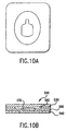
- the reinforcement layer 640 comprises raised walls 642 which are formed directly on the bottom surface of the lower compartment layer 630. Similar to the embodiment shown in FIGS. 5A-5C and as shown in FIG. 6B , the lower compartment layer 630 is made to conform to the raised walls 642, thereby forming a well 662 into which sample material 670 is deposited. The upper compartment layer 620 is attached to the lower compartment layer 630 by means of the seal 650, thereby forming a compartment 660 for containing the sample material 670. The lower compartment layer 642 and the reinforcement layer 640 are attached to a carrier 680.
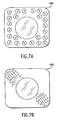
- the reinforcement layer 440 may be mesh-like, scored or perforated with holes (see FIGS. 7A and 7B ). Such sheets or meshes are well known in the art and are often available in pre-manufactured form.
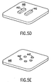
- the reinforcement layer 440 may be decorated with ornamental cavities or raised shapes to create a pleasing aesthetic effect (see FIG. 8 ). These shapes may be within or beyond the seal.
- the reinforcement layer also may have multiple cavities (see FIG. 9 ). These cavities may be disconnected from one another as shown in FIG. 9 or connected to each other or a combination of both.
- the lower compartment layer conforms to the contours of at least one of these cavities, thereby forming at least one well. Sample material may complete-ly or partially fill every well or less than all of the wells.
- One seal 450 may surround all the cavities. Alternatively, each cavity or subsets of cavities may be sealed individually.
- the sampler device 510 has a multi-level compartment 560.
- the multi-level compartment is created.by two reinforcement layers 540, 590 joined together.
- the lower compartment layer 530 conforms to the contours of both reinforcement layers 540, 590.
- Art work or advertisements may be attractively and advantageously displayed on the sampler device of the present invention.
- the configuration of the sampler device allows an uninterrupted display of art work or ads, which may be printed on any combination of the upper compartment, lower compartment and reinforcement layers 20, 30, 40. All components of the present invention together provide a substantially continuous surface to print a complete advertisement or work of art.
- the present invention also relates to methods of packaging sample material.
- the methods of the present invention generally include the following steps: forming a reinforcement layer having a sidewall that defines a cavity or enclosure; securely attaching a lower compartment layer to the reinforcement layer such that a portion of the lower compartment layer fits within the cavity and conforms to the contours of the cavity; depositing sample material onto the portion of the lower compartment layer within the cavity; and sealing an upper compartment layer to the lower compartment layer around the sample material.
- the reinforcement layer 40 (such as is shown in FIGS. 1 , 2A and 2B ) is formed by die cutting a first sheet or layer of pressure sensitive stock in a manner known in the art to form a cavity 42 with an outer periphery 43 and a sidewall 44 extending throughout the thickness of the first sheet of pressure sensitive stock except for the release liner.
- the outer periphery 43 of the cavity 42 may be any of a variety of shapes.
- the lower compartment layer 30 is made from a second sheet of pressure sensitive stock. The release liner of the second sheet is removed, and the lower compartment layer 30 is placed over the reinforcement layer 40 such that the pressure sensitive adhesive on the lower compartment layer 30 contacts the reinforcement layer 40 and also such that a portion of the lower compartment layer 30 lies within the cavity 42 of the reinforcement layer 40, thereby forming a well 62.
- the lower compartment layer 30 is made to conform to the cavity 42 of the reinforcement layer 40. In other words, the lower compartment layer 30 is securely attached to both the upper surface 46 and the sidewall 44 of the reinforcement layer 40. In the sampler device 10 shown in FIG. 2A , the lower compartment layer 30 is attached to substantially the entire sidewall 44 of the reinforcement layer 40. However, the objects of the present invention may be achieved by attaching only a portion of the well 62 must be attached to the sidewall 44. This is effected by passing the two layers though a set of rubber rollers. Alternatively, other equipment may be used such as ironing dies, brushes, pads or air nozzles. The brushes may be magnetic, or they may be made of fibers.
- the pressure sensitive stock composing the lower compartment layer 30 is a flexible sheet and will therefore closely follow the contours of the cavity 42 of the first sheet.
- the next step is to deposit sample material 70 into the well 62 of the lower compartment layer 30.
- the amount of sample material 70 deposited outside the well 62 is minimized.
- the amount of sample material 70 is determined by the dimensions of the sampler device 10, which may vary widely.
- a preferred amount of sample material 70 for each sampler device 10 is 50 mg to 3000 mg. However, the amount of sample material is not limited to this range.
- a third sheet of material, i.e., the upper compartment layer 20, is then placed over the lower compartment layer 30 and the sample material 70. Because both the upper and lower compartment layers 20,30 directly contact the sample material 70, both must have barrier properties.
- the upper compartment layer 20 is attached to the lower compartment layer 30 by known methods of heat sealing.
- the seal 50 is formed just beyond the outer periphery 43 of the cavity 42 in order to maintain as much of the sample material 70 within the cavity 62 as possible for purposes of protection and aesthetic appearance as explained above. Sealing the upper and lower compartment layers 20, 30 encloses the sample material 70 within the compartment 60 in which it will be protected and preserved until used.
- the three layers further may be cut or trimmed in a predetermined shape to form individual label-like sampler devices 10. Waste matrix is removed while the release liner of the reinforcement layer 40 is left intact. Alternatively, the release liner is removed and replaced with a separate carrier 280 (as shown in FIG. 4 ) via the pressure sensitive adhesive of the reinforcement layer 40. The sampler device 10 may then be distributed in this form. If the material chosen for the reinforcement layer 40 or lower compartment layer does not include a layer of pressure sensitive adhesive, another appropriate adhesive may be used.
- raised walls are formed on a base layer to form the reinforcement layer. Reinforcement layers formed in this way are illustrated in FIG. 5C .
- the raised walls 442 may be printed, spot coated, sprayed or selectively transferred to the base layer. These raised walls 442 define enclosures which function to protect the sample material 470.
- the lower compartment layer 430 is then attached to the reinforcement layer 440 such that it conforms to the raised walls 442 on the reinforcement layer 440.
- Sample material 470 is deposited on the lower compartment layer 430 such that substantially all of the sample material 470 is contained within the protective enclosure.
- the upper compartment layer 420 is then sealed to the lower compartment layer 430, thereby maintaining the sample material 470 within a protected compartment.
- the remaining steps in this alternative method are substantially similar to those of the first method.
- a reinforcement layer comprising raised walls or raised segments (without a base layer) may be formed directly on the lower compartment layer. This may be done by depositing material onto the surface of the lower compartment layer opposite to the surface upon which sample material is deposited. Again, these raised walls or raised segments define the protective enclosure to which the lower compartment layer conforms and in which the sample material is contained.
- a sampler device is shown in FIGS. 6A-6C .
- the reinforcement layer may be formed from certain rigid materials that are embossed, cold formed or thermoformed to create raised walls.
- the lower compartment layer is then attached to this reinforcement layer such that it conforms to the raised walls.
- the lower compartment layer and the reinforcement layer may be joined as a laminate, and the laminate may be embossed or thermoformed to create the raised walls.
- the reinforcement layer may be an olefin or other thermoplastic polymer.
- An alternative method of the present invention contemplates mass production of sampler devices using standard label manufacturing equipment.
- This method generally includes the following steps: die cutting a first sheet or layer of pressure sensitive stock to form a plurality of cavities; permanently adhering a second flexible sheet of pressure sensitive stock over the first sheet such that portions of the second sheet lie within each cavity and conform to the contours of each cavity; depositing sample material on the second sheet, such that substantially all of the sample material lies within the cavities; placing a third sheet over the second sheet and the sample material; sealing the third sheet to the second sheet around each deposit of sample material; and die cutting the three joined sheets into individual sampler devices.
- the release liner of the first sheet of pressure sensitive stock remains undisturbed during the die cutting procedures.
- the release liner, to which each individual sampler device is attached is one continuous sheet or web, and it may be wound in rolls, folded, or cut into sheets for subsequent processing.
- the sampler devices 10 When wound in rolls on a release liner, the sampler devices 10 must conform to the curvature of the rolls, and separation of the devices 10 from the release liner must be avoided. To this end, the first sheet may be scored or perforated for increased flexibility.
Claims (20)
- Dispositif échantillonneur (10) comprenant :une couche de compartiment supérieur (20) présentant des propriétés barrières d'échantillon ;une couche de compartiment inférieur (30) présentant des propriétés barrières d'échantillon ;un joint (50) fixant la couche de compartiment supérieur (20) à la couche de compartiment inférieur (30), formant ainsi au moins un compartiment fermé (60) pour contenir un matériau échantillon (70) ; etau moins une couche de renfort (40) fixée de manière concordante à au moins l'une de la couche de compartiment supérieur (20) et de la couche de compartiment inférieur (30) pour protéger le au moins un compartiment, dans lequel la couche de compartiment inférieur est en contact et est attachée solidement à la surface supérieur (46) et à sensiblement toute la paroi latéral (44) de la couche de renfort (40), de manière que la couche de compartiment inférieur suit les contours de la couche de renfort (40), et dans lequel la au moins une couche de renfort (40) définit une enveloppe qui contient sensiblement l'ensemble du au moins un compartiment (60).
- Dispositif échantillonneur (10) selon la revendication 1, dans lequel au moins une couche de renfort (40) comporte une paroi latérale (44) entourant sensiblement l'ensemble du au moins un compartiment (60).
- Dispositif échantillonneur (10) selon la revendication 1, dans lequel la au moins une couche de renfort (40) est fixée de manière permanente à au moins une de la couche de compartiment supérieur (20) et de la couche de compartiment inférieur (30).
- Dispositif échantillonneur (10) selon la revendication 2 ou 3, dans lequel la au moins une couche de renfort (40) et la couche de compartiment inférieur (30) sont formées à partir d'un matériau stratifié.
- Dispositif échantillonneur (10) selon l'une quelconque des revendications précédentes, dans lequel la paroi latérale (44) est formée par un trou poinçonné à travers la au moins une couche de renfort (40).
- Dispositif échantillonneur (10) selon la revendication 2 ou 3, dans lequel la au moins une couche de renfort (40) comporte une paroi surélevée fixée à une couche de base, dans lequel la paroi surélevée forme la paroi latérale (44).
- Dispositif échantillonneur (10) selon la revendication 1 ou 2, dans lequel la paroi latérale (44) est formée par une paroi surélevée fixée à la couche de compartiment inférieur (30).
- Dispositif échantillonneur (10) selon la revendication 2 ou 3, dans lequel la paroi latérale (44) est formée par gaufrage.
- Dispositif échantillonneur (10) selon la revendication 2 ou 3, dans lequel la paroi latérale (44) est continue.
- Dispositif échantillonneur (10) selon l'une quelconque des revendications précédentes, dans lequel la couche de compartiment supérieur (20) est continue par rapport à la couche de compartiment inférieur (30).
- Dispositif échantillonneur (10) selon l'une quelconque des revendications précédentes, dans lequel la au moins une couche de renfort (40) est fixée à un support séparé.
- Dispositif échantillonneur (10) selon l'une quelconque des revendications précédentes, dans lequel la au moins une couche de renfort (40) est fixée en permanence à au moins l'une de la couche de compartiment supérieur (20) et de la couche de compartiment inférieur (30).
- Dispositif échantillonneur (10) selon l'une quelconque des revendications précédentes, dans lequel le dispositif échantillonneur est flexible.
- Dispositif échantillonneur (10) selon l'une quelconque des revendications précédentes, dans lequel les compartiments supérieur et inférieur (20, 30) ont des surfaces supérieures et inférieures généralement parallèles.
- Dispositif échantillonneur (10) selon l'une quelconque des revendications précédentes, dans lequel le dispositif est sensiblement plan.
- Dispositif échantillonneur (10) selon l'une quelconque des revendications précédentes, dans lequel le joint (50) est un joint permanent.
- Dispositif échantillonneur (10) selon l'une quelconque des revendications 1 à 15, dans lequel le joint (50) est séparable de sorte qu'un utilisateur peut séparer au moins une partie de la couche de compartiment supérieur (20) de la couche de compartiment inférieur (30).
- Procédé d'emballage de matériau échantillon (70), comprenant les étapes consistant à :découper à l'emporte-pièce une première feuille de pâte autocollante sensiblement rigide pour former une pluralité de cavités (42) avec des dimensions définies par ladite emporte-pièce et par l'épaisseur ou la profondeur de la première feuille de pâte autocollante sensiblement rigide, dans lequel la première feuille comprend une doublure anti-adhésive ;coller de manière permanente une deuxième feuille flexible de pâte autocollante sensiblement rigide sur la première feuille de telle sorte que des parties de la deuxième feuille flexible concorde sensiblement avec les contours de chaque cavité (42) ;placer une pluralité de dépôts de matériau échantillon sur la deuxième feuille de telle sorte que sensiblement la totalité de chaque dépôt de matériau échantillon se trouve à l'intérieur de chaque cavité (42) ;placer une troisième feuille sur la deuxième feuille et la pluralité de dépôts de matériau échantillon ;sceller la troisième feuille avec la deuxième feuille autour de chaque dépôt de matériau échantillon ; etdécouper à l'emporte-pièce la première, la deuxième et la troisième feuille en dispositifs échantillonneurs individuels (10) de telle sorte que chaque dispositif échantillonneur (10) reste fixé à la doublure anti-adhésive de la première feuille et dans lequel chaque dispositif échantillonneur (10) contient un dépôt de matériau échantillon etdans lequel l'épaisseur de ladite première feuille de pâte autocollante sensiblement rigide protège chaque dispositif échantillonneur (10) contre la rupture due aux forces de compression.
- Procédé d'emballage de matériau échantillon (70) selon la revendication 19, comprenant, en outre, l'étape consistant à enrouler la doublure antiadhésive et les dispositifs échantillonneurs (10) pour former un rouleau pour le stockage.
- Procédé d'emballage de matériau échantillon (70) selon la revendication 19, comprenant, en outre, l'étape consistant à fixer chaque dispositif échantillonneur (10) à un support pour la distribution.
Priority Applications (1)
| Application Number | Priority Date | Filing Date | Title |
|---|---|---|---|
| DE69736388.0T DE69736388T3 (de) | 1996-09-12 | 1997-09-11 | Probenahmevorrichtung mit verstärkter kammer und verfahren zum verpacken von probenmaterial |
Applications Claiming Priority (3)
| Application Number | Priority Date | Filing Date | Title |
|---|---|---|---|
| US712779 | 1985-03-18 | ||
| US08/712,779 US5879769A (en) | 1996-09-12 | 1996-09-12 | Sampler device having a reinforced compartment and method of packaging sample material |
| PCT/US1997/016361 WO1998010917A1 (fr) | 1996-09-12 | 1997-09-11 | Dispositif echantillonneur avec compartiment renforce et procede d'emballage de materiaux echantillons |
Publications (4)
| Publication Number | Publication Date |
|---|---|
| EP0925171A1 EP0925171A1 (fr) | 1999-06-30 |
| EP0925171A4 EP0925171A4 (fr) | 2003-08-13 |
| EP0925171B1 EP0925171B1 (fr) | 2006-07-26 |
| EP0925171B2 true EP0925171B2 (fr) | 2016-09-07 |
Family
ID=24863534
Family Applications (1)
| Application Number | Title | Priority Date | Filing Date |
|---|---|---|---|
| EP97941636.9A Expired - Lifetime EP0925171B2 (fr) | 1996-09-12 | 1997-09-11 | Dispositif echantillonneur avec compartiment renforce et procede d'emballage de materiaux echantillons |
Country Status (15)
| Country | Link |
|---|---|
| US (2) | US5879769A (fr) |
| EP (1) | EP0925171B2 (fr) |
| JP (2) | JP3801650B2 (fr) |
| KR (1) | KR100346523B1 (fr) |
| AT (1) | ATE333981T2 (fr) |
| AU (1) | AU713696B2 (fr) |
| BR (1) | BR9711782A (fr) |
| CA (1) | CA2266049C (fr) |
| DE (2) | DE925171T1 (fr) |
| ES (1) | ES2148118T5 (fr) |
| IL (1) | IL128916A0 (fr) |
| NZ (1) | NZ334697A (fr) |
| PL (1) | PL184722B1 (fr) |
| PT (1) | PT925171E (fr) |
| WO (1) | WO1998010917A1 (fr) |
Families Citing this family (42)
| Publication number | Priority date | Publication date | Assignee | Title |
|---|---|---|---|---|
| US6691872B1 (en) * | 1997-04-08 | 2004-02-17 | Aki, Inc. | Method of making a cosmetic sampler using bulk thin film application techniques |
| US6326069B1 (en) | 1997-06-13 | 2001-12-04 | Arcade, Inc. | Fluid sampler pouch with internal supportive structure |
| AU1942599A (en) | 1998-02-10 | 1999-08-23 | Delta Graphics, Inc. | Product sampler |
| CA2333276A1 (fr) * | 1998-05-15 | 1999-11-25 | Arcade, Inc. | Procede de fabrication de multiples compartiments miniatures pour prelevements |
| US6202852B1 (en) | 1999-06-30 | 2001-03-20 | Bettina M. Jones | Method and apparatus for color identification of cosmetic products |
| US6301860B1 (en) | 1999-08-25 | 2001-10-16 | Color Prelude, Inc. | Liquid product sampler package with frame structure for enhanced burst strength |
| FR2801179B1 (fr) * | 1999-11-23 | 2002-08-30 | Delviel | Procede d'encapsulation d'une composition topique |
| US10874192B2 (en) * | 2000-03-20 | 2020-12-29 | Orlandi, Inc. | Fragrance sampler insert |
| FR2810969B1 (fr) * | 2000-06-30 | 2002-11-15 | Coty Sa | Boitier ultra-plat pour encart |
| WO2002014174A1 (fr) * | 2000-08-15 | 2002-02-21 | Girl Squared, Llc | Dispositif de divertissement et d'education presentant un support d'affichage de message et un echantillon de produits d'amelioration de message |
| EP1370217A4 (fr) * | 2001-02-02 | 2005-04-13 | Lh Skin Care Llc | Systeme de conditionnement de produits cosmetiques |
| FR2821061B1 (fr) * | 2001-02-22 | 2003-04-04 | Oreal | Procede de conditionnement d'un produit |
| EP1234521A3 (fr) | 2001-02-23 | 2003-07-02 | Arcade Marketing, Inc. | Echantillon de produit fluide avec zone de dépôt du produit |
| US6607078B2 (en) * | 2001-04-16 | 2003-08-19 | Ccl Label, Inc. | Sample packet label and related method of manufacture |
| GB0123151D0 (en) | 2001-09-26 | 2001-11-21 | Biotrace Ltd | Device for use in monitoring swab technique |
| US7051894B2 (en) * | 2001-10-01 | 2006-05-30 | Wm. Wrigley Jr. Company | Circular dispensing container with a hinged lid |
| EP1506035A1 (fr) * | 2002-05-06 | 2005-02-16 | Vectura Limited | Dispositif d'application destine a l'administration topique d'agents pharmaceutiques |
| JP3467035B1 (ja) * | 2002-06-13 | 2003-11-17 | プロモツール株式会社 | 商品見本収納方法およびその容器 |
| US6915903B2 (en) * | 2003-05-13 | 2005-07-12 | Dell Products L.P. | Reinforced packaging system |
| SE527398C2 (sv) * | 2003-05-30 | 2006-02-28 | Micvac Ab | Envägsventil för livsmedelsförpackning |
| US6929128B2 (en) * | 2003-06-12 | 2005-08-16 | Marietta Corporation | Product sampler packet assembly with enhanced burst strength and method of manufacture |
| BR0303884A (pt) * | 2003-09-25 | 2005-05-31 | Mfr Produtos Promocionais Ltda | Amostras de cosmético e processo para sua fabricação |
| WO2005118459A1 (fr) * | 2004-05-18 | 2005-12-15 | Garry Tsaur | Procede de remplissage de tubes pour ecouvillons remplis de liquide |
| US20060021901A1 (en) * | 2004-08-02 | 2006-02-02 | Sven Dobler | Removable sampler |
| US20090241981A1 (en) * | 2004-08-02 | 2009-10-01 | Sven Dobler | Cosmetic products applicator |
| FR2876361B1 (fr) * | 2004-10-13 | 2008-07-25 | Oreal | Dispositif de conditionnement et/ou d'application d'au moins un produit, notamment cosmetique |
| FR2877647B1 (fr) * | 2004-11-10 | 2006-12-15 | Socoplan Soc Par Actions Simpl | Support de conditionnement pourvu de moyens de rigidification et de repartition d'un effort de pression |
| US7669382B2 (en) * | 2005-03-25 | 2010-03-02 | Pella Corporation | Window installation method |
| US20070074742A1 (en) * | 2005-09-30 | 2007-04-05 | Szu-Min Lin | AER wet cleaning indicator |
| US20080028552A1 (en) * | 2005-12-14 | 2008-02-07 | Nicholas Powley | Single use applicator |
| US20100002963A1 (en) * | 2008-07-01 | 2010-01-07 | Victor Paul Holbert | Reclosable food package with improved shelf life |
| US20100108778A1 (en) * | 2008-10-30 | 2010-05-06 | Greenland Steven J | Device for containing and releasing a volatile substance |
| CN102256781A (zh) | 2008-12-31 | 2011-11-23 | Aki公司 | 用于容纳和释放试用物的装置 |
| US9272830B2 (en) | 2009-08-24 | 2016-03-01 | Aki, Inc. | Unitized package of card and fluid vessel |
| PL2289816T3 (pl) | 2009-08-24 | 2015-04-30 | Aki Inc | Jednostkowe opakowanie i sposób jego wykonania |
| US8414994B2 (en) * | 2010-04-01 | 2013-04-09 | Express Card And Label Co., Inc. | Machine applicable note-carried liquid pack |
| US20120304600A1 (en) * | 2011-05-31 | 2012-12-06 | Ward Kraft, Inc. | Containment Device And Method Of Use |
| US9332814B2 (en) * | 2013-03-15 | 2016-05-10 | Barbara Brock | Compact organizer for cosmetics |
| US10661923B2 (en) * | 2018-01-18 | 2020-05-26 | Je Matadi, Inc. | System to manufacture a disposable single use applicator assembly with a chemical composition |
| US20220009673A1 (en) * | 2020-07-09 | 2022-01-13 | Anatolia Liliana Marghitoiu | Method for employing containers with removable sample compartments |
| WO2022147301A1 (fr) * | 2020-12-31 | 2022-07-07 | Terri Apanasewicz Llc | Récipient d'emballage |
| WO2023031657A1 (fr) * | 2021-09-06 | 2023-03-09 | Gutierrez Lemus Maria Enilde | Testeur de substances multiples qui comprend des feuilles de revêtement indépendantes |
Citations (4)
| Publication number | Priority date | Publication date | Assignee | Title |
|---|---|---|---|---|
| CH448485A (de) † | 1965-04-30 | 1967-12-15 | Hassia Verpackung Ag | Verpackungsbehälter sowie Verfahren und Vorrichtung zu seiner Herstellung |
| DE7108921U (de) † | 1971-08-05 | Farina J | Zeitungs oder Zeitschnftenbeilage, die eine Warenprobe enthalt | |
| WO1991017931A1 (fr) † | 1990-05-22 | 1991-11-28 | Frank Meehan | Emballage et procede d'emballage pour un echantillon de liquide |
| DE9419824U1 (de) † | 1994-12-10 | 1995-02-02 | Klocke Verpackungs Service | Probepackung zur Einlage in Zeitschriften |
Family Cites Families (50)
| Publication number | Priority date | Publication date | Assignee | Title |
|---|---|---|---|---|
| US2061139A (en) * | 1934-12-22 | 1936-11-17 | Lady Esther Company | Sample shipping package |
| US2185386A (en) * | 1938-03-22 | 1940-01-02 | Joseph E Valentine | Sampling device |
| US2214510A (en) * | 1939-07-25 | 1940-09-10 | Robinson Allan | Toilet package |
| US2291379A (en) * | 1940-10-15 | 1942-07-28 | Gen Electric | Cosmetic cream container |
| US2561400A (en) * | 1946-04-15 | 1951-07-24 | Jacque C Morrell | Cosmetic package |
| US2878061A (en) * | 1957-10-22 | 1959-03-17 | Puro Co Inc | Moth preventive and deodorant dispensers |
| US3139712A (en) * | 1959-05-18 | 1964-07-07 | Beltx Corp | Packaging |
| US3421615A (en) * | 1967-10-03 | 1969-01-14 | Prym Inc William | Dispensing blister package with closable opening in the blister member |
| US3503493A (en) * | 1968-01-08 | 1970-03-31 | Hoffmann La Roche | Medicament packaging device |
| US3657857A (en) * | 1970-02-05 | 1972-04-25 | Beltx Corp | Method of and apparatus for forming packages |
| US4145001A (en) * | 1977-09-15 | 1979-03-20 | American Can Company | Packaging for controlled release of volatile substances |
| EP0046021B1 (fr) * | 1980-08-11 | 1985-02-13 | Imperial Chemical Industries Plc | Sachets et méthode pour leur production |
| US4430843A (en) * | 1981-08-20 | 1984-02-14 | Dennis Favale | Mailing and display package |
| US4419396A (en) * | 1982-08-18 | 1983-12-06 | Terutaka Sugimoto | Three-dimensional perfumed seal |
| GB8319096D0 (en) * | 1983-07-14 | 1983-08-17 | Harlands Of Hull Ltd | Topical dressings |
| US4656068A (en) * | 1983-12-23 | 1987-04-07 | Plicon Corporation | Pellable seal package |
| US4614299A (en) * | 1984-06-13 | 1986-09-30 | International Flavors & Fragrances Inc. | Article which dispenses at a constant rate a volatile composition, and process for using same |
| US5072831A (en) * | 1985-04-10 | 1991-12-17 | Webcraft Technologies, Inc. | Rub-off advertising sampler and method of manufacture |
| US5037139A (en) * | 1985-04-10 | 1991-08-06 | Webcraft Technologies, Inc. | Advertising sampler and method of manufacture |
| GB8528428D0 (en) * | 1985-11-19 | 1985-12-24 | Bunzl Flexpack Ltd | Packaging of fresh fruit & vegetables |
| US5690130A (en) * | 1986-06-17 | 1997-11-25 | Color Prelude Inc. | Cosmetic sampler with integral applicator |
| US4751934A (en) * | 1986-06-17 | 1988-06-21 | Alford Industries, Inc. | Cosmetic sampler |
| US5647941A (en) * | 1986-06-17 | 1997-07-15 | Color Prelude, Inc. | Method of making a lipstick sampler |
| US5192386A (en) * | 1986-06-17 | 1993-03-09 | Alford Industries Inc. | Method of making a cosmetic sampler |
| US4848378A (en) * | 1986-06-17 | 1989-07-18 | Alford Industries Inc. | Cosmetic sampler |
| US4890872A (en) * | 1986-10-08 | 1990-01-02 | Webcraft Technologies, Inc. | Flat paper sheet item for distributing a thin layer of material |
| US4786534A (en) * | 1987-02-02 | 1988-11-22 | Business Systems Enterprises, Inc. | Disposable package for liquid material and method of making same |
| US4884680A (en) * | 1987-02-17 | 1989-12-05 | Avon Products, Inc. | Cosmetic display |
| US4876136A (en) * | 1987-06-22 | 1989-10-24 | Minnesota Mining And Manufacturing Company | Lipstick sampling device |
| US4824143A (en) * | 1987-10-08 | 1989-04-25 | Webcraft Technologies, Inc. | Lipstick sampler and method of fabrication |
| US4878775A (en) * | 1987-10-28 | 1989-11-07 | Minnesota Mining And Manufacturing Company | Liquid transfer device |
| US4881359A (en) * | 1987-10-30 | 1989-11-21 | W. R. Grace & Co. | Method for making a vacuum skin package |
| US5161688A (en) * | 1988-04-22 | 1992-11-10 | Muchin Jerome D | Sampler and method of making the same |
| US4874129A (en) * | 1988-06-30 | 1989-10-17 | Dow Corning Corporation | Multi-laminate fragrance release device |
| JPH046760Y2 (fr) * | 1988-12-27 | 1992-02-24 | ||
| FR2643798B1 (fr) * | 1989-03-03 | 1991-07-05 | Lir France Sa | Boite de maquillage perfectionnee |
| US4998671A (en) * | 1989-10-20 | 1991-03-12 | The Drackett Company | Multiple compartment flexible package |
| US5114766A (en) * | 1990-07-13 | 1992-05-19 | Jacques Pierre J | Container provided with a multilayer cover with venting provisions and related method |
| US5236749A (en) * | 1991-12-02 | 1993-08-17 | Ewing William D | Blister package |
| US5404693A (en) * | 1992-04-17 | 1995-04-11 | Sencorp Systems, Inc. | Method for making plastic blister packages |
| US5248537A (en) * | 1992-07-22 | 1993-09-28 | Danbury Printing & Litho, Inc. | Non-contaminating fragrance releasing insert for magazines |
| US5439172A (en) * | 1992-07-29 | 1995-08-08 | The Beautiful Bouquet Company Limited | Planar sampler for a liquid volatile material and method |
| US5289917A (en) * | 1993-04-05 | 1994-03-01 | Press-A-Lite | Combined greeting card and flashlight gift package |
| US5439100A (en) * | 1993-05-04 | 1995-08-08 | The Dial Corp. | Packaging system for dispensing cartridge for volatiles |
| US5418022A (en) * | 1993-06-01 | 1995-05-23 | Minnesota Mining And Manufacturing Company | Method of forming a pocket from a spunbonded olefin sheet and a microbial resistant package produced thereby |
| US5704481A (en) * | 1994-11-18 | 1998-01-06 | Ivex Corporation | Easy open package |
| US5568866A (en) * | 1994-12-30 | 1996-10-29 | Westlake Ventures, L.L.C. | Sample package |
| US5622263A (en) * | 1995-05-01 | 1997-04-22 | Webcraft Technologies, Inc. | Sampler package and method of making the same |
| US5718955A (en) * | 1996-03-12 | 1998-02-17 | The Procter & Gamble Company | Composite for controlling oxygen flux into thermal cells |
| US5799675A (en) | 1997-03-03 | 1998-09-01 | Color Prelude, Inc. | Screen printed product sampler in hermetically sealed package |
-
1996
- 1996-09-12 US US08/712,779 patent/US5879769A/en not_active Expired - Lifetime
-
1997
- 1997-09-11 CA CA002266049A patent/CA2266049C/fr not_active Expired - Lifetime
- 1997-09-11 DE DE0925171T patent/DE925171T1/de active Pending
- 1997-09-11 JP JP51396698A patent/JP3801650B2/ja not_active Expired - Fee Related
- 1997-09-11 AT AT97941636T patent/ATE333981T2/de active
- 1997-09-11 IL IL12891697A patent/IL128916A0/xx unknown
- 1997-09-11 PL PL97332157A patent/PL184722B1/pl unknown
- 1997-09-11 BR BR9711782-0A patent/BR9711782A/pt not_active IP Right Cessation
- 1997-09-11 DE DE69736388.0T patent/DE69736388T3/de not_active Expired - Lifetime
- 1997-09-11 EP EP97941636.9A patent/EP0925171B2/fr not_active Expired - Lifetime
- 1997-09-11 KR KR1019997002074A patent/KR100346523B1/ko not_active IP Right Cessation
- 1997-09-11 PT PT97941636T patent/PT925171E/pt unknown
- 1997-09-11 AU AU43502/97A patent/AU713696B2/en not_active Ceased
- 1997-09-11 NZ NZ334697A patent/NZ334697A/xx not_active IP Right Cessation
- 1997-09-11 WO PCT/US1997/016361 patent/WO1998010917A1/fr active IP Right Grant
- 1997-09-11 ES ES97941636.9T patent/ES2148118T5/es not_active Expired - Lifetime
-
1998
- 1998-11-10 US US09/189,966 patent/US6250049B1/en not_active Expired - Lifetime
-
2004
- 2004-07-21 JP JP2004213319A patent/JP2004352366A/ja active Pending
Patent Citations (4)
| Publication number | Priority date | Publication date | Assignee | Title |
|---|---|---|---|---|
| DE7108921U (de) † | 1971-08-05 | Farina J | Zeitungs oder Zeitschnftenbeilage, die eine Warenprobe enthalt | |
| CH448485A (de) † | 1965-04-30 | 1967-12-15 | Hassia Verpackung Ag | Verpackungsbehälter sowie Verfahren und Vorrichtung zu seiner Herstellung |
| WO1991017931A1 (fr) † | 1990-05-22 | 1991-11-28 | Frank Meehan | Emballage et procede d'emballage pour un echantillon de liquide |
| DE9419824U1 (de) † | 1994-12-10 | 1995-02-02 | Klocke Verpackungs Service | Probepackung zur Einlage in Zeitschriften |
Also Published As
| Publication number | Publication date |
|---|---|
| PL332157A1 (en) | 1999-08-30 |
| JP2001503354A (ja) | 2001-03-13 |
| CA2266049A1 (fr) | 1998-03-19 |
| DE69736388T3 (de) | 2017-01-05 |
| US6250049B1 (en) | 2001-06-26 |
| PT925171E (pt) | 2006-10-31 |
| EP0925171A1 (fr) | 1999-06-30 |
| AU4350297A (en) | 1998-04-02 |
| ES2148118T3 (es) | 2007-05-01 |
| JP2004352366A (ja) | 2004-12-16 |
| CA2266049C (fr) | 2004-11-30 |
| DE925171T1 (de) | 2000-08-31 |
| WO1998010917A1 (fr) | 1998-03-19 |
| US5879769A (en) | 1999-03-09 |
| PL184722B1 (pl) | 2002-12-31 |
| IL128916A0 (en) | 2000-02-17 |
| NZ334697A (en) | 2000-09-29 |
| ES2148118T5 (es) | 2017-05-05 |
| BR9711782A (pt) | 2000-01-18 |
| ATE333981T2 (de) | 2006-08-15 |
| DE69736388T2 (de) | 2007-09-13 |
| KR20000036068A (ko) | 2000-06-26 |
| DE69736388D1 (de) | 2006-09-07 |
| ES2148118T1 (es) | 2000-10-16 |
| JP3801650B2 (ja) | 2006-07-26 |
| AU713696B2 (en) | 1999-12-09 |
| EP0925171A4 (fr) | 2003-08-13 |
| KR100346523B1 (ko) | 2002-08-03 |
| EP0925171B1 (fr) | 2006-07-26 |
Similar Documents
| Publication | Publication Date | Title |
|---|---|---|
| EP0925171B2 (fr) | Dispositif echantillonneur avec compartiment renforce et procede d'emballage de materiaux echantillons | |
| EP1034073B1 (fr) | Poche d'echantillonneur de fluide a structure de support interne | |
| US3764002A (en) | Carded package | |
| US5842324A (en) | Method for producing sample package | |
| EP1078865B1 (fr) | Emballage pour echantillon liquide avec structure d'armature | |
| KR101705392B1 (ko) | 결합형 패키지 및 이의 제조 방법 | |
| EP0525530B1 (fr) | Dispositifs de prise d'échantillon de parfum et leur procédé de fabrication | |
| JPH01167084A (ja) | 包装体 | |
| IE20070811A1 (en) | Flexible wipes pack | |
| US6772884B2 (en) | Ultra-flat box for insert | |
| EP2817239B1 (fr) | Emballage unitaire | |
| MXPA99002356A (es) | Dispositivo de muestreo que tiene un compartimiento reforzado y metodo para empacar material de muestra | |
| JP3551721B2 (ja) | 化粧料充填容器 | |
| JP2000083729A (ja) | 化粧料充填容器 | |
| JPS6120610Y2 (fr) | ||
| JP3551720B2 (ja) | 化粧料充填容器 | |
| WO2007013799A1 (fr) | Emballage pour mouchoirs en papier humidifiés |
Legal Events
| Date | Code | Title | Description |
|---|---|---|---|
| PUAI | Public reference made under article 153(3) epc to a published international application that has entered the european phase |
Free format text: ORIGINAL CODE: 0009012 |
|
| 17P | Request for examination filed |
Effective date: 19990324 |
|
| AK | Designated contracting states |
Kind code of ref document: A1 Designated state(s): AT BE CH DE DK ES FI FR GB GR IE IT LI LU MC NL PT SE |
|
| EL | Fr: translation of claims filed | ||
| RAP1 | Party data changed (applicant data changed or rights of an application transferred) |
Owner name: ARCADE, INC. |
|
| DET | De: translation of patent claims | ||
| REG | Reference to a national code |
Ref country code: ES Ref legal event code: BA2A Ref document number: 2148118 Country of ref document: ES Kind code of ref document: T1 |
|
| A4 | Supplementary search report drawn up and despatched |
Effective date: 20030627 |
|
| 17Q | First examination report despatched |
Effective date: 20040315 |
|
| RAP1 | Party data changed (applicant data changed or rights of an application transferred) |
Owner name: AKI, INC. |
|
| GRAP | Despatch of communication of intention to grant a patent |
Free format text: ORIGINAL CODE: EPIDOSNIGR1 |
|
| GRAS | Grant fee paid |
Free format text: ORIGINAL CODE: EPIDOSNIGR3 |
|
| GRAA | (expected) grant |
Free format text: ORIGINAL CODE: 0009210 |
|
| AK | Designated contracting states |
Kind code of ref document: B1 Designated state(s): AT BE CH DE DK ES FI FR GB GR IE IT LI LU MC NL PT SE |
|
| PG25 | Lapsed in a contracting state [announced via postgrant information from national office to epo] |
Ref country code: NL Free format text: LAPSE BECAUSE OF FAILURE TO SUBMIT A TRANSLATION OF THE DESCRIPTION OR TO PAY THE FEE WITHIN THE PRESCRIBED TIME-LIMIT Effective date: 20060726 Ref country code: FI Free format text: LAPSE BECAUSE OF FAILURE TO SUBMIT A TRANSLATION OF THE DESCRIPTION OR TO PAY THE FEE WITHIN THE PRESCRIBED TIME-LIMIT Effective date: 20060726 |
|
| REG | Reference to a national code |
Ref country code: GB Ref legal event code: FG4D |
|
| REG | Reference to a national code |
Ref country code: CH Ref legal event code: NV Representative=s name: KIRKER & CIE SA Ref country code: CH Ref legal event code: EP |
|
| REG | Reference to a national code |
Ref country code: IE Ref legal event code: FG4D |
|
| REF | Corresponds to: |
Ref document number: 69736388 Country of ref document: DE Date of ref document: 20060907 Kind code of ref document: P |
|
| PG25 | Lapsed in a contracting state [announced via postgrant information from national office to epo] |
Ref country code: MC Free format text: LAPSE BECAUSE OF NON-PAYMENT OF DUE FEES Effective date: 20060930 |
|
| PG25 | Lapsed in a contracting state [announced via postgrant information from national office to epo] |
Ref country code: SE Free format text: LAPSE BECAUSE OF FAILURE TO SUBMIT A TRANSLATION OF THE DESCRIPTION OR TO PAY THE FEE WITHIN THE PRESCRIBED TIME-LIMIT Effective date: 20061026 Ref country code: DK Free format text: LAPSE BECAUSE OF FAILURE TO SUBMIT A TRANSLATION OF THE DESCRIPTION OR TO PAY THE FEE WITHIN THE PRESCRIBED TIME-LIMIT Effective date: 20061026 |
|
| REG | Reference to a national code |
Ref country code: PT Ref legal event code: SC4A Effective date: 20060811 |
|
| REG | Reference to a national code |
Ref country code: CH Ref legal event code: NV Representative=s name: CRONIN INTELLECTUAL PROPERTY |
|
| NLV1 | Nl: lapsed or annulled due to failure to fulfill the requirements of art. 29p and 29m of the patents act | ||
| ET | Fr: translation filed | ||
| REG | Reference to a national code |
Ref country code: CH Ref legal event code: PCAR Free format text: CRONIN INTELLECTUAL PROPERTY;CHEMIN DE PRECOSSY 31;1260 NYON (CH) |
|
| PLBI | Opposition filed |
Free format text: ORIGINAL CODE: 0009260 |
|
| REG | Reference to a national code |
Ref country code: ES Ref legal event code: FG2A Ref document number: 2148118 Country of ref document: ES Kind code of ref document: T3 |
|
| 26 | Opposition filed |
Opponent name: BEIERSDORF AG Effective date: 20070426 Opponent name: KLOCKE VERPACKUNGS-SERVICE GMBH Effective date: 20070423 |
|
| PLAX | Notice of opposition and request to file observation + time limit sent |
Free format text: ORIGINAL CODE: EPIDOSNOBS2 |
|
| PLAF | Information modified related to communication of a notice of opposition and request to file observations + time limit |
Free format text: ORIGINAL CODE: EPIDOSCOBS2 |
|
| PLAF | Information modified related to communication of a notice of opposition and request to file observations + time limit |
Free format text: ORIGINAL CODE: EPIDOSCOBS2 |
|
| PLBB | Reply of patent proprietor to notice(s) of opposition received |
Free format text: ORIGINAL CODE: EPIDOSNOBS3 |
|
| PG25 | Lapsed in a contracting state [announced via postgrant information from national office to epo] |
Ref country code: GR Free format text: LAPSE BECAUSE OF FAILURE TO SUBMIT A TRANSLATION OF THE DESCRIPTION OR TO PAY THE FEE WITHIN THE PRESCRIBED TIME-LIMIT Effective date: 20061027 |
|
| PG25 | Lapsed in a contracting state [announced via postgrant information from national office to epo] |
Ref country code: LU Free format text: LAPSE BECAUSE OF NON-PAYMENT OF DUE FEES Effective date: 20060911 |
|
| PLAY | Examination report in opposition despatched + time limit |
Free format text: ORIGINAL CODE: EPIDOSNORE2 |
|
| PLAH | Information related to despatch of examination report in opposition + time limit modified |
Free format text: ORIGINAL CODE: EPIDOSCORE2 |
|
| PLBC | Reply to examination report in opposition received |
Free format text: ORIGINAL CODE: EPIDOSNORE3 |
|
| APAH | Appeal reference modified |
Free format text: ORIGINAL CODE: EPIDOSCREFNO |
|
| APBM | Appeal reference recorded |
Free format text: ORIGINAL CODE: EPIDOSNREFNO |
|
| APBP | Date of receipt of notice of appeal recorded |
Free format text: ORIGINAL CODE: EPIDOSNNOA2O |
|
| APBM | Appeal reference recorded |
Free format text: ORIGINAL CODE: EPIDOSNREFNO |
|
| APBP | Date of receipt of notice of appeal recorded |
Free format text: ORIGINAL CODE: EPIDOSNNOA2O |
|
| APBQ | Date of receipt of statement of grounds of appeal recorded |
Free format text: ORIGINAL CODE: EPIDOSNNOA3O |
|
| APBQ | Date of receipt of statement of grounds of appeal recorded |
Free format text: ORIGINAL CODE: EPIDOSNNOA3O |
|
| PLAB | Opposition data, opponent's data or that of the opponent's representative modified |
Free format text: ORIGINAL CODE: 0009299OPPO |
|
| R26 | Opposition filed (corrected) |
Opponent name: KLOCKE VERPACKUNGS-SERVICE GMBH Effective date: 20070423 Opponent name: BEIERSDORF AG Effective date: 20070426 |
|
| REG | Reference to a national code |
Ref country code: FR Ref legal event code: PLFP Year of fee payment: 19 |
|
| APBU | Appeal procedure closed |
Free format text: ORIGINAL CODE: EPIDOSNNOA9O |
|
| PG25 | Lapsed in a contracting state [announced via postgrant information from national office to epo] |
Ref country code: IT Free format text: LAPSE BECAUSE OF NON-PAYMENT OF DUE FEES Effective date: 20150911 |
|
| RIC2 | Information provided on ipc code assigned after grant |
Ipc: A45D 40/00 20060101AFI20160504BHEP Ipc: B65D 75/32 20060101ALI20160504BHEP Ipc: B65B 11/50 20060101ALI20160504BHEP |
|
| PUAH | Patent maintained in amended form |
Free format text: ORIGINAL CODE: 0009272 |
|
| STAA | Information on the status of an ep patent application or granted ep patent |
Free format text: STATUS: PATENT MAINTAINED AS AMENDED |
|
| 27A | Patent maintained in amended form |
Effective date: 20160907 |
|
| AK | Designated contracting states |
Kind code of ref document: B2 Designated state(s): AT BE CH DE DK ES FI FR GB GR IE IT LI LU MC NL PT SE |
|
| REG | Reference to a national code |
Ref country code: DE Ref legal event code: R102 Ref document number: 69736388 Country of ref document: DE |
|
| REG | Reference to a national code |
Ref country code: CH Ref legal event code: AELC |
|
| REG | Reference to a national code |
Ref country code: FR Ref legal event code: PLFP Year of fee payment: 20 |
|
| PGFP | Annual fee paid to national office [announced via postgrant information from national office to epo] |
Ref country code: FR Payment date: 20160929 Year of fee payment: 20 Ref country code: AT Payment date: 20161010 Year of fee payment: 20 |
|
| REG | Reference to a national code |
Ref country code: AT Ref legal event code: UEP Ref document number: 333981 Country of ref document: AT Kind code of ref document: T Effective date: 20160907 |
|
| PGFP | Annual fee paid to national office [announced via postgrant information from national office to epo] |
Ref country code: BE Payment date: 20160928 Year of fee payment: 20 |
|
| PG25 | Lapsed in a contracting state [announced via postgrant information from national office to epo] |
Ref country code: IT Free format text: LAPSE BECAUSE OF NON-PAYMENT OF DUE FEES Effective date: 20150911 |
|
| PGFP | Annual fee paid to national office [announced via postgrant information from national office to epo] |
Ref country code: GB Payment date: 20161005 Year of fee payment: 20 Ref country code: CH Payment date: 20161013 Year of fee payment: 20 Ref country code: IE Payment date: 20161010 Year of fee payment: 20 Ref country code: DE Payment date: 20161004 Year of fee payment: 20 |
|
| PGRI | Patent reinstated in contracting state [announced from national office to epo] |
Ref country code: IT Effective date: 20161118 |
|
| PGFP | Annual fee paid to national office [announced via postgrant information from national office to epo] |
Ref country code: IT Payment date: 20160929 Year of fee payment: 20 Ref country code: ES Payment date: 20161011 Year of fee payment: 20 Ref country code: PT Payment date: 20161004 Year of fee payment: 20 |
|
| REG | Reference to a national code |
Ref country code: ES Ref legal event code: DC2A Ref document number: 2148118 Country of ref document: ES Kind code of ref document: T5 Effective date: 20170505 |
|
| REG | Reference to a national code |
Ref country code: DE Ref legal event code: R071 Ref document number: 69736388 Country of ref document: DE |
|
| REG | Reference to a national code |
Ref country code: CH Ref legal event code: PL |
|
| REG | Reference to a national code |
Ref country code: GB Ref legal event code: PE20 Expiry date: 20170910 |
|
| REG | Reference to a national code |
Ref country code: AT Ref legal event code: MK07 Ref document number: 333981 Country of ref document: AT Kind code of ref document: T Effective date: 20170911 |
|
| REG | Reference to a national code |
Ref country code: IE Ref legal event code: MK9A |
|
| PG25 | Lapsed in a contracting state [announced via postgrant information from national office to epo] |
Ref country code: PT Free format text: LAPSE BECAUSE OF EXPIRATION OF PROTECTION Effective date: 20170919 Ref country code: GB Free format text: LAPSE BECAUSE OF EXPIRATION OF PROTECTION Effective date: 20170910 |
|
| REG | Reference to a national code |
Ref country code: BE Ref legal event code: MK Effective date: 20170911 Ref country code: BE Ref legal event code: FP Effective date: 20161123 |
|
| PG25 | Lapsed in a contracting state [announced via postgrant information from national office to epo] |
Ref country code: IE Free format text: LAPSE BECAUSE OF EXPIRATION OF PROTECTION Effective date: 20170911 |
|
| REG | Reference to a national code |
Ref country code: ES Ref legal event code: FD2A Effective date: 20180508 |
|
| PG25 | Lapsed in a contracting state [announced via postgrant information from national office to epo] |
Ref country code: ES Free format text: LAPSE BECAUSE OF EXPIRATION OF PROTECTION Effective date: 20170912 |