EP0925151B1 - Abrasive article and method of making - Google Patents
Abrasive article and method of making Download PDFInfo
- Publication number
- EP0925151B1 EP0925151B1 EP96932205A EP96932205A EP0925151B1 EP 0925151 B1 EP0925151 B1 EP 0925151B1 EP 96932205 A EP96932205 A EP 96932205A EP 96932205 A EP96932205 A EP 96932205A EP 0925151 B1 EP0925151 B1 EP 0925151B1
- Authority
- EP
- European Patent Office
- Prior art keywords
- abrasive
- particles
- grinding aid
- precisely shaped
- binder
- Prior art date
- Legal status (The legal status is an assumption and is not a legal conclusion. Google has not performed a legal analysis and makes no representation as to the accuracy of the status listed.)
- Expired - Lifetime
Links
Images
Classifications
-
- B—PERFORMING OPERATIONS; TRANSPORTING
- B24—GRINDING; POLISHING
- B24D—TOOLS FOR GRINDING, BUFFING OR SHARPENING
- B24D3/00—Physical features of abrasive bodies, or sheets, e.g. abrasive surfaces of special nature; Abrasive bodies or sheets characterised by their constituents
- B24D3/34—Physical features of abrasive bodies, or sheets, e.g. abrasive surfaces of special nature; Abrasive bodies or sheets characterised by their constituents characterised by additives enhancing special physical properties, e.g. wear resistance, electric conductivity, self-cleaning properties
- B24D3/342—Physical features of abrasive bodies, or sheets, e.g. abrasive surfaces of special nature; Abrasive bodies or sheets characterised by their constituents characterised by additives enhancing special physical properties, e.g. wear resistance, electric conductivity, self-cleaning properties incorporated in the bonding agent
- B24D3/344—Physical features of abrasive bodies, or sheets, e.g. abrasive surfaces of special nature; Abrasive bodies or sheets characterised by their constituents characterised by additives enhancing special physical properties, e.g. wear resistance, electric conductivity, self-cleaning properties incorporated in the bonding agent the bonding agent being organic
-
- B—PERFORMING OPERATIONS; TRANSPORTING
- B24—GRINDING; POLISHING
- B24D—TOOLS FOR GRINDING, BUFFING OR SHARPENING
- B24D11/00—Constructional features of flexible abrasive materials; Special features in the manufacture of such materials
-
- B—PERFORMING OPERATIONS; TRANSPORTING
- B24—GRINDING; POLISHING
- B24D—TOOLS FOR GRINDING, BUFFING OR SHARPENING
- B24D11/00—Constructional features of flexible abrasive materials; Special features in the manufacture of such materials
- B24D11/001—Manufacture of flexible abrasive materials
-
- B—PERFORMING OPERATIONS; TRANSPORTING
- B24—GRINDING; POLISHING
- B24D—TOOLS FOR GRINDING, BUFFING OR SHARPENING
- B24D3/00—Physical features of abrasive bodies, or sheets, e.g. abrasive surfaces of special nature; Abrasive bodies or sheets characterised by their constituents
- B24D3/02—Physical features of abrasive bodies, or sheets, e.g. abrasive surfaces of special nature; Abrasive bodies or sheets characterised by their constituents the constituent being used as bonding agent
- B24D3/20—Physical features of abrasive bodies, or sheets, e.g. abrasive surfaces of special nature; Abrasive bodies or sheets characterised by their constituents the constituent being used as bonding agent and being essentially organic
- B24D3/28—Resins or natural or synthetic macromolecular compounds
-
- B—PERFORMING OPERATIONS; TRANSPORTING
- B24—GRINDING; POLISHING
- B24D—TOOLS FOR GRINDING, BUFFING OR SHARPENING
- B24D3/00—Physical features of abrasive bodies, or sheets, e.g. abrasive surfaces of special nature; Abrasive bodies or sheets characterised by their constituents
- B24D3/34—Physical features of abrasive bodies, or sheets, e.g. abrasive surfaces of special nature; Abrasive bodies or sheets characterised by their constituents characterised by additives enhancing special physical properties, e.g. wear resistance, electric conductivity, self-cleaning properties
Definitions
- This invention relates to coated and bonded abrasive articles, and a method for making a coated abrasive article.
- WO95/01241 refers to a method of preparing precisely shaped particles. Furthermore an abrasive article is described which includes a plurality of precisely shaped abrasive particles that comprise abrasive grits and a binder formed from an addition-polymerizable binder precursor.
- WO95/20469 relates to a coated abrasive containing erodible agglomerates and abrasive grains.
- the erodible agglomerates consist essentially of a grinding aid and are in the form of rods.
- coated abrasive articles typically consist of a layer of abrasive grits adhered to a backing. Generally only a small fraction of the abrasive grits in this layer are actually utilized during the useful life of the coated abrasive article. A large proportion of the abrasive grits in this layer are wasted. Furthermore, the backing, one of the more expensive components of the coated abrasive article, must also be disposed of before it has worn out.
- abrasive grits can be distributed in a coated abrasive article in such a way as to prolong the life of the article.
- One such way involves incorporating abrasive agglomerates in the coated abrasive article.
- Abrasive agglomerates consist of abrasive grits bonded together by means of a binder to form a mass.
- the use of abrasive agglomerates having random shapes and sizes makes it difficult to predictably control the quantity of abrasive grits that come into contact with the surface of a workpiece. For this reason, it would be desirable to have an economical way to prepare precisely shaped abrasive agglomerates.
- the present invention refers to a coated abrasive article comprising:
- the invention provides a coated abrasive article comprising:
- the above coated abrasive article can be made by a method comprising the steps of:
- the invention in yet another embodiment relates to a bonded abrasive article comprising a bonding medium, a plurality of abrasive grits and a plurality of precisely shaped grinding aid particles which are free of abrasive grits, wherein the precisely shaped grinding aid particles are pyramids comprising a binder, obtainable from a thermosetting binder precursor, and a plurality of grinding aid particulates, and wherein the bonding medium serves to form a shaped mass of the abrasive grits and precisely shaped grinding aid particles.
- the precisely shaped grinding aid particles can be prepared by a method comprising the steps of:
- Steps (f) and (g) can be conducted simultaneously.
- the binder that contains grinding aid particulates is removed from the at least one cavity of the production tool in step (f). Materials other than grinding aid particulate can be included with the binder precursor.
- the curing zone can contain a source of thermal energy, a source of radiation energy, or both. Suitable sources of radiation energy include electron beam, visible light, and ultraviolet light. In a variation of the general method, curing can be effected by thermal energy or by a combination of radiation energy and thermal energy.
- steps (d), (e), and (f) be carried out on a continuous basis or be carried out in a continuous manner.
- the production tool be an endless web (belt), or a drum, preferably a cylindrical drum, which will rotate about its axis.
- a web having two ends can be used. Such a two-ended web travels from an unwind station to a rewind station.
- the production tool have a plurality of cavities.
- the binder precursor is solidified so as to be converted into a handleable binder.
- the binder can be converted into particles by several means.
- the binder when the binder is removed from the cavities of the production tool, it is released in the form of individual particles.
- the resulting particles preferably have shapes that are essentially the same as the shapes of the cavities of the production tool.
- the particles have shapes that are determined by the shapes of the cavities of the production tool.
- steps (f) and (g) are accomplished simultaneously, because the shaped particles have their characteristic form when they are released from the cavities of the production tool.
- the binder is removed from the major surface of the production tool in the form of a sheet comprising shaped portions that are of essentially of the same size and shape of the cavities of the production tool, but joined together by a relatively thin connecting layer of the material of the binder.
- the sheet is then broken or crushed along the thin connecting layer of binder material to form the precisely shaped particles.
- the particles can be screened or classified to remove any undesired particles. If the connecting layer of the binder material is carefully broken or crushed, the resulting particles can have shapes that are essentially the same as those of the cavities of the production tool.
- a carrier web to deliver binder precursor to the production tool.
- the binder precursor can be coated onto one major surface, e.g., the front surface, of a carrier web and then the resulting coated carrier web is brought into contact with the continuous surface of the production tool that contains the cavities. After at least partial curing, i.e., solidifying, of the binder precursor in the production tool, the binder, which preferentially adheres to the surface of the carrier web, is removed first from the production tool and then from the carrier web.
- the binder precursor is coated onto the continuous surface of the production tool having cavities, whereby such cavities are filled, and the carrier web is brought into contact with the continuous surface of the production tool containing the binder precursor in such a manner that the binder precursor contained in the cavities contacts the surface of the carrier web.
- the binder adheres to the surface carrier web rather than to the production tool.
- the binder can then be removed from the carrier web. Subsequently, the precisely shaped particles are formed.
- the precisely shaped particles can be modified by means of additives for use in abrading applications, either by themselves or as a component of an abrasive article.
- the particles of this invention can be used to prepare abrasive articles comprising a plurality of shaped particles.
- the particles can be bonded together to form a shaped mass, e.g., a wheel.
- the particles can be bonded to a backing to form a coated abrasive article.
- This invention makes it possible to design particles suitable for specific applications by varying'the shape and composition of the particles.
- the process of this invention provides a simple, fast, and economical method for manufacturing particles, especially abrasive particles having a precise shape.
- the process of this invention makes it possible to accurately make abrasive particles having the same dimensions from batch to batch, thereby leading to more consistent abrasive articles.
- the surface area of a coated abrasive layer of the invention comprises 5 to 90 percent, preferably 10 to 75 percent, most preferably 20 to 40 percent precisely shaped grinding aid particles.
- the bonded abrasive of the invention is in the form of a wheel, including a out off wheel.
- the volume percent of the precisely shaped grinding aid particles in a bonded abrasive ranges from about 5 to 85 percent, preferably between 5 to 75 percent, more preferably between 5 to 60 percent and most preferably between 10 to 60 percent.
- the precisely shaped grinding aid particles are free of abrasive grits and, it is generally preferred that they consist essentially of the binder and grinding aid particulates.
- binder precursor means any material that is conformable or can be made to be conformable by heat or pressure or both and that can be rendered non-conformable by means of radiation energy or thermal energy or both.
- solidified, handleable binder means a binder precursor that has been polymerized or cured to such a degree that it will not substantially flow or experience a substantial change in shape.
- solidified, handleable binder does not mean that the binder precursor is always fully polymerized or cured, but that it is sufficiently polymerized or cured to allow removal thereof from the production tool while the production tool continues to move, without leading to substantial change in shape of the binder. After the binder is removed from the production tool, the binder can be exposed to an additional energy source to provide additional cure or polymerization of the binder.
- binder is synonymous with the expression “solidified, handleable binder”.
- a method of making a particulate involves precisely shaped particles comprising a solidified, handleable binder.
- precisely shaped means that the binder precursor is cured, polymerized or solidified in a cavity of a production tool. After the binder precursor is solidified in the cavity, the resulting solidified binder is removed from the cavity. In some instances during this removal process, a particle is formed and during the removal process, edges of the particle may break. Additionally, when the particles are removed from the cavities, two, three or more particles may be interconnected at a common edge or otherwise remain together. In other instances, a sheet of particles is removed and then this sheet is further processed (e.g., crushing, breaking, ball milling and the like) to form individual particles.
- the resulting individual particles may have rounded edges and/or several (i.e., two, three, four or more particles may remain together). It is within the scope of this invention, that the term precisely shaped covers both broken edge particles and rounded edge particles. Additionally it is within the scope of this invention, that the term precisely shaped covers two, three, four or more individual particles that interconnect or otherwise remain together.
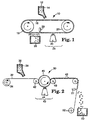
- FIG. 1 illustrates an apparatus capable of carrying out the method of this invention to make the precisely shaped particles.
- binder precursor 12 and grinding aid particulates are fed by gravity from a hopper 14 onto a production tool 16, which is in the form of an endless belt.
- the belt 16 travels over two rolls 18, 20, at least one of which is power driven.
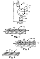
- FIG. 6 is a perspective view of a segment of the production tool 16.
- the production tool 16 is a three-dimensional body having a continuous surface 21 containing an opening 22 that provides access to a cavity 23 in the three-dimensional body.
- the binder precursor 12 fills at least a portion of cavity 23.
- the binder precursor 12 then travels through a curing zone 24 where it is exposed to an energy source 25 to at least partially cure the binder precursor 12 to form a solidified, handleable binder.
- Particles of precisely shaped grinding aid particles 26 are removed from the production tool 16 and collected in a container 28.
- External means 29, e.g., ultrasonic energy, can be used to help release the particles 26 from the production tool 16. Debris left in the production tool can be cleaned away before any fresh binder precursor is fed to the production tool.
- FIG. 2 illustrates another variation of apparatus capable of carrying out the method of this invention.
- Apparatus 30 comprises a carrier web 32 which is fed from an unwind station 34.
- Unwind station 34 is in the form of a roll.
- the carrier web 32 can be made of a material such as paper, cloth, polymeric film, nonwoven web, vulcanized fibre, combinations thereof and treated versions thereof.
- the preferred material for the carrier web 32 is a polymeric film, such as, for example, a polyester film.
- the carrier web 32 is transparent to radiation.
- a binder precursor 36 and grinding aid particulates are fed by gravity from a hopper 38 onto a major surface of the carrier web 32.
- the major surface of the carrier web 32 containing the binder precursor 36 is forced against the surface of a production tool 40 by means of a nip roll 42.
- the surface of the production tool 40 that contacts the carrier web is curved, but it is otherwise identical to that of the segment of the production tool shown in FIG. 6.
- the nip roll 42 also aids in forcing the binder precursor 36 into the cavities of the production tool 40.
- the binder precursor 36 then travels through a curing zone 43 where it is exposed to an energy source 44 to at least partially cure the binder precursor 36 to form a solidified, handleable binder.
- the carrier web 32 containing the solidified, handleable binder is passed over a nip roll 46.
- the precisely shaped grinding aid particles 48 are removed from the carrier web 32 and collected in a container 50. External means 51, e.g., ultrasonic energy, can be used to help release the particles 48 from the carrier web 32.
- the carrier web 32 is then recovered at rewind station 52 so that it can be reused.
- Rewind station 52 is in the form of a roll.
- the carrier web can contain a thin, water-soluble layer on the major surface thereof that receives the binder precursor 36 from the hopper 38.
- the water-soluble layer will come into contact with the binder precursor 36.
- the combination of carrier web 32 and solidified, handleable binder is subjected to a source of water, whereby the water dissolves the water-solubie layer on the carrier web 32, thereby bringing about separation of the particles from the carrier web 32.
- a water-soluble layer useful for this variation is a layer of a water-soluble polymer, e.g., polyvinyl alcohol, polyvinyl pyrrolidone, and cellulose derivatives.
- FIG. 3 illustrates another variation of an apparatus capable of carrying out the method.
- binder precursor 72 and grinding aid particulates are knife coated from a hopper 74 onto a production tool 76.
- the production tool is in the form of a cylindrical drum and has an axis 78.
- the continuous surface of the production tool 76 is curved, but it is otherwise identical to the segment of the production tool shown in FIG. 6.
- the binder precursor 72 travels through a curing zone 79 where it is exposed to an energy source 80 to at least partially cure the binder precursor 72 to form a solidified, handleable binder.
- the particles of solidified, handleable binder 82 resulting from the curing step of the process are removed from the production tool 76 and collected in a hopper 84. Removal is preferably carried out by mechanical means, e.g., a water jet. It is preferred that any debris remaining in the production tool 76 be removed before any fresh binder precursor is introduced. Debris removal can be accomplished by a brush, an air jet, or any other conventional technique. Although not shown in FIG. 3, additional means can be used to aid in removing the particles of binder from the production tool 76.
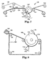
- FIG. 7 illustrates another variation of an apparatus capable of carrying out the method.
- Apparatus 120 comprised a production tool 122 in the form of web, which was fed from a first unwind station 124.
- Unwind station 124 was in the form of a roll.
- the production tool 122 is preferably made of a polymeric material that is transparent to radiation, more preferably transparent to ultraviolet and/or visible light.
- the production tool can be made of a 5 polymer having a polyethylene backbone and fluoroaliphatic groups attached thereto. This polymer is further described in WO 92/15626, published September 17, 1990. The ethylene polymer is bonded to polyester.
- the production tool can comprise a pattern of cavities in the form of pyramids having square bases and disposed such that the bases were butted up against each other.
- the surface of the production tool containing the cavities can be similar to the segment of the production tool shown in FIG. 6.
- the production tool 122 leaves the unwind station 124, a carrier web 126 leaves a second unwind station 128.
- the carrier web 126 can be made of a polyvinyl alcohol coated paper, commercially available from Schoeller Technical Papers, Inc. of Pulaski, New York; stock number 89-84-4.
- a binder precursor 130 and grinding aid particulate applied by means of a coater 132 into the cavities of the production tool 122.
- the portion of the production tool 134 containing the binder precursor is brought into contact with the carrier web 126 by means of a nip roll 136.
- the portion of the production tool 134 containing the binder precursor and the carrier web 126 is forced against a mandrel 138.
- the mandrel 138 rotates about an axis 140.
- radiation energy from radiation source 141 in a curing zone 142 is transmitted through the production tool 122 and into the binder precursor.
- the source of radiation energy can be a medium pressure mercury vapor ultraviolet lamp operating at 600 watts/inch (240 watts/cm).
- the binder precursor Upon exposure to the energy source, the binder precursor is converted into a solidified, handleable binder.
- Both the production tool containing the solidified, handleable binder and the carrier web are continuously moved through the curing zone 142 by means of the mandrel 138.
- the carrier web 126 is separated from the production tool containing the binder in the vicinity of a nip roll 143.
- the carrier web 126 is rewound on a rewind station 144.
- An example of a commercially available ultrasonic horn is that which is available from Branson under the model number "108".
- FIG. 8 illustrates another variation of an apparatus capable of carrying out the method.
- Apparatus 160 comprised a production tool 162 in the form of an endless belt, which traversed a series of rollers 164, at least one of which is power-driven.
- a binder precursor 166 and grinding aid particulate are applied by means of a knife coater 168 into the cavities of the production tool 162.
- the binder precursor 166 then travels through a curing zone 170 where it is exposed to a source of radiation energy 172.
- the source of radiation energy can be a medium pressure mercury vapor ultraviolet lamp operating at 600 watts/inch (240 watts/cm).
- the process is continuous and upon exposure to the energy source 172, the binder precursor 166 is converted into a solidified, handleable binder.
- the particles 178 preferentially should adhere to a smooth-surfaced roll 174. Immediately after leaving the curing zone 170, the particles 178 are removed from the smooth-surfaced roll 174 by a skiving means 176 and collected by means of vacuum (not shown).
- the production tool is a three-dimensional body having at least one continuous surface.
- the continuous surface contains at least one opening, preferably a plurality of openings, formed in the continuous surface. Each opening provides access to a cavity formed in the three-dimensional body.
- continuous means characterized by uninterrupted extension in space; the openings and cavities are features in the continuous surface, but they do not break the surface into a plurality of individual surfaces.
- the production tool can be in the form of a web, a belt, e.g., an endless belt, a sheet, a coating roll, or a sleeve mounted on a coating roll.
- the production tool be one that allows continuous operations, such as, for example, an endless belt or a cylindrical coating roll that rotates about an axis.
- a cylindrical coating roll is in the form of a right cylinder, has a diameter of from about 25 to about 45 cm, and is constructed of a rigid material.
- Apparatus utilizing a two-ended web can also be adapted to provide continuous operations.
- the preferred materials for a production tool are polymers, such as polyolefins, e.g., polypropylene, or metals, such as nickel.
- the production tool can also be formed from a ceramic material.
- a production tool made of metal can be fabricated by engraving, photolithography, hobbing, etching, knurling, assembling a plurality of metal parts machined in the desired configuration, die punching, or other mechanical means, or by electroforming.
- the preferred method for preparing a metal production tool or master tool is diamond turning.
- Another preferred technique for making the master tool and/or a metal production tool is to use a cutting knurl process. This cutting knurl process is further described in PCT Patent Application No. PCT/US95/13074. For example, a cylindrical, eight inch diameter, 28 inch long, 1026 mild steel workpiece was first plated with a thin layer of bright nickel to prevent corrosion and improve adhesion to plated copper. Next, 0.050 in.
- a Zeus Cut-Knurling Tool Model No. 209 was provided with a high speed steel ("HSS”) first knurling wheel in the top position.
- First knurling wheel had a 30° left tooth incline relative to the axis of the wheel, 36 teeth per inch (“TPI”), with the teeth having a 90° included angle at the tooth ridge.
- the tool was also provided with a HSS second knurling wheel in the bottom position.
- the second knurling wheel had a 0° tooth incline angle relative to the wheel axis, 36 TPI, with a 90° included angle at the tooth ridge.
- Both wheel orientations were adjusted by setting the wheel mounting posts to the 200 mm (7.9 inch) workpiece O. D. position.
- the wheel axes were each approximately 30° relative to the horizontal center plane of the Zeus Cut-Knurling Tool.
- the Cut-Knurling Tool was then mounted on the cross slide of the clausing lathe. The height of the tool was adjusted so that both wheels would contact the workpiece at the same time. The first wheel in the top position was then removed. Coolant flow was directed at the second wheel to wash away chips as they formed.
- the resulting knurled workpiece surface was covered with a knurl pattern of 36.7 square-based pyramids per inch measured in the direction parallel to an edge of the base of the pyramid, having an average height of 0.0099 inches.
- the tops of the pyramids were rounded corresponding to the rounded valley of the knurl wheels.
- the peaks of the pyramidal pattern had a 11.5° helix angle with respect to a plane perpendicular to the longitudinal axis of the workpiece.
- the workpiece was coated with a protective layer of electroless nickel to prevent corrosion and improve polymer release characteristics before use.
- the knurled workpiece described above was used to make a production tooling. First the workpiece and a nip roll were installed below an extruder. The knurled workpiece was held at 60°C (140°F) and the nip roll at 21°C (70°F). Escorene "Polypropylene 3445" at 214°C (417°F) was extruded on to the knurled workpiece and forced between the workpiece and nip roll as the workpiece and nip roll were rotated. A 0.022 inch thick seamless film was collected at 3.6 meters/minute (11.8 fpm). The surface of the film had an uninterrupted pattern of pyramidal pockets on its surface which were the inverse of those on the knurled workpiece.
- the production tool may also contain a release coating to permit easier removal of the binder from the cavities and to minimize wear of the production tool.
- release coatings include hard coatings such as metal carbides, metal nitrides, metal borides, diamond, or diamond-like carbon.
- a heated production tool which is preferably made from metal A heated tool may allow easier processing, more rapid curing, easier release of the shaped particles from the tool. Further information on production tools can be found in U.S. Patent No. 5,435,816.
- a polymeric production tool can be replicated from an original master tool. This is especially preferred when the production tool is in the form of a belt or web.
- One advantage of polymeric tools over metal tools is cost.
- Another advantage of polymeric tools is the capability of allowing radiation to pass from the radiation source through the production tool and into the binder precursor.
- a polymeric production tool can be prepared by coating a molten thermoplastic resin, such as polypropylene, onto the master tool. The molten resin can then be quenched to give a thermoplastic replica of the master tool. This polymeric replica can then be utilized as the production tool.
- the surface of the production tool may contain a release coating, such as a silicone-based material or a fluorochemical-based material, to improve the releasability of the binder from the production tool. It is also within the scope of this invention to incorporate a release agent into the polymer from which the production tool is formed. Typical release agents include silicone-based materials and fluorochemical-based materials. It is within the scope of this invention to prepare production tools from polymers that exhibit good release characteristics. Such a polymer is described in WO 92/15626, published September 17, 1992.
- That reference describes a fluorochemical graft copolymer comprising: a base polymer comprising polymerized units derived from monomers having terminal olefinic double bonds, having a moiety comprising a fluoroaliphatic group grafted thereto.
- the grafted fluoroaliphatic group is generally derived from a fluorochemical olefin comprising a fluoroaliphatic group and a polymerizable double bond.
- the fluoroaliphatic group of the fluorochemical olefin is generally bonded to the polymerizable double bond through a linking group.
- the metal master tool can be made by the same methods that can be used to make metal production tools. Other methods of preparing production tools are described in U.S. Patent No. 5,435,816.
- the conditions of the method should be set such that any heat generated in the curing zone does not adversely affect the production tool.
- At least one continuous surface of the production tool contains at least one cavity, preferably a plurality of cavities.
- the solidified, handleable binder precursor will acquire a shape corresponding to the shape of the cavity.
- a cavity has the geometric shape of a pyramid. It is also within the scope of this invention that a given production tool may contain a variety of cavities of different shapes or cavities of different sizes or both. In the case of a web or belt, the cavity can extend completely through the production tool. The cavities can abutt or have land areas between them. It is preferred that the sides of the cavities have a slope associated them to allow easier removal of the binder from the production tool.
- the cavities may all be the same shape with the same dimensions.
- the plurality of precisely shaped particles will all have essentially the same size and shape.
- the cavities may all be the same shape with different dimensions.
- the cavities may all be the same dimensions, with different shapes.
- the resulting precisely shaped particles will be the same size, with different shapes.
- the cavities may have different shapes and different sizes. In this instance, the resulting precisely shaped particles will have different shapes and sizes.
- Binder precursors suitable for this invention comprise a thermosetting resin that is capable of being cured by radiation energy or thermal energy.
- the binder precursor can polymerize via a condensation curing mechanism or an addition mechanism.
- the preferred binder precursors polymerize via an addition mechanism.
- the binder precursor can polymerize via a free radical mechanism or a cationic mechanism or both mechanisms.
- the binder precursor can be unfilled or can contain conventional filler material.
- the binder precursor is preferably capable of being cured by radiation energy or thermal energy.
- Sources of radiation energy include electron beam energy, ultraviolet light, visible light, and laser light. If ultraviolet or visible light is utilized, a photoinitiator is preferably included in the mixture. Upon being exposed to ultraviolet or visible light, the photoinitiator generates a free radical source or a cationic source. This free radical source or cationic source then initiates the polymerization of the binder precursor.
- a photoinitiator is optional when a source of electron beam energy is utilized.
- acrylate includes both acrylates and methacrylates.
- Acrylated urethanes are diacrylate esters of hydroxy terminated isocyanate extended polyesters or polyethers.
- Examples of commercially available acrylated urethanes include "UVITHANE 782", available from Morton Thiokol Chemical, and "CMD 6600”, “CMD 8400”, and “CMD 8805”, available from Radcure Specialties.
- Acrylated epoxies are diacrylate esters of epoxy resins, such as the diacrylate esters of bisphenol A epoxy resin.
- Examples of commercially available acrylated epoxies include "CMD 3500”, “CMD 3600”, and “CMD 3700", available from Radcure Specialties.
- Ethylenically unsaturated compounds include both monomeric and polymeric compounds that contain atoms of carbon, hydrogen and oxygen, and optionally, nitrogen and the halogens. Oxygen or nitrogen atoms or both are generally present in ether, ester, urethane, amide, and urea groups. Ethylenically unsaturated compounds preferably have a molecular weight of less than about 4,000 and are preferably esters resulting from the reaction of compounds containing aliphatic monohydroxy groups or aliphatic polyhydroxy groups and unsaturated carboxylic acids, such as acrylic acid, methacrylic acid, itaconic acid, crotonic acid, isocrotonic acid, maleic acid, and the like.
- acrylates include methyl methacrylate, ethyl methacrylate, ethylene glycol diacrylate, ethylene glycol methacrylate, hexanediol diacrylate, triethylene glycol diacrylate, trimethylolpropane triacrylate, glycerol triacrylate, pentaerythritol triacrylate, pentaerythritol methacrylate, and pentaerythritol tetraacrylate.
- Other ethylenically unsaturated compounds include monoallyl, polyallyl, and polymethylallyl esters and amides of carboxylic acids, such as diallyl phthalate, diallyl adipate, and N,N-diallyladipamide.
- Still other ethylenically unsaturated compounds include styrene, divinyl benzene, and vinyl toluene.
- Other nitrogen-containing, ethylenically unsaturated compounds include tris(2-acryloyl-oxyethyl)isocyanurate, 1,3,5-tri(2-methacryloxyethyl)-s-triazine, acrylamide, methylacrylamide, N-methylacrylamide, N,N-dimethylacrylamide, N-vinylpyrrolidone, and N-vinylpiperidone.
- the aminoplast can be monomeric or oligomeric.
- the aminoplast resins have at least one pendant ⁇ , ⁇ -unsaturated carbonyl group per molecule. These ⁇ , ⁇ -unsaturated carbonyl groups can be acrylate, methacrylate, or acrylamide groups. Examples of such resins include N-hydroxymethyl-acrylamide, N,N'-oxydimethylenebisacrylamide, ortho and para acrylamidomethylated phenol, acrylamidomethylated phenolic novolac, and combinations thereof. These materials are further described in U.S. Patent Nos. 4,903,440; 5,055,112 and 5,236,472.
- Isocyanurate derivatives having at least one pendant acrylate group and isocyanate derivatives having at least one pendant acrylate group are further described in U.S. Patent No. 4,652,274.
- the preferred isocyanurate material is a triacrylate of tris(hydroxyethyl) isocyanurate.
- vinyl ethers suitable for this invention include vinyl ether functionalized urethane oligomers, commercially available from Allied Signal under the trade designations "VE 4010”, “VE 4015”, “VE 2010”, “VE 2020”, and "VE 4020”.
- Epoxies have an oxirane ring and are polymerized by the ring opening.
- Epoxy resins include monomeric epoxy resins and polymeric epoxy resins. These resins can vary greatly in the nature of their backbones and substituent groups.
- the backbone may be of any type normally associated with epoxy resins and substituent groups thereon can be any group free of an active hydrogen atom that is reactive with an oxirane ring at room temperature.
- substituent groups for epoxy resins include halogens, ester groups, ether groups, sulfonate groups, siloxane groups, nitro groups, and phosphate groups.
- epoxy resins preferred for this invention include 2,2-bis[4-(2,3-epoxypropoxy)phenyl]propane (diglycidyl ether of bisphenol A) and materials under the trade designation "Epon 828", “Epon 1004" and “Epon 1001F”, commercially available from Shell Chemical Co., "DER-331”, “DER-332” and “DER-334”, commercially available from Dow Chemical Co.
- Other suitable epoxy resins include glycidyl ethers of phenol formaldehyde novolac (e.g., "DEN-431” and "DEN-428", commercially available from Dow Chemical Co.),
- the epoxy resins of the invention can polymerize via a cationic mechanism with the addition of an appropriate photoinitiator(s). These resins are further described in U.S. Patent Nos. 4,318,766 and 4,751,138.
- photoinitiators that generate a free radical source when exposed to ultraviolet light include, but are not limited to, those selected from the group consisting of organic peroxides, azo compounds, quinones, benzophenones, nitroso compounds, acyl halides, hydrazones, mercapto compounds, pyrylium compounds, triacrylimidazoles, bisimidazoles, chloroalkyltriazines, benzoin ethers, benzil ketals, thioxanthones, and acetophenone derivatives, and mixtures thereof.
- Examples of photoinitiators that generate a free radical source when exposed to visible radiation are described in U.S. Patent No. 4,735,632.
- Cationic photoinitiators generate an acid source to initiate the polymerization of an epoxy resin or a urethane.
- Cationic photoinitiators can include a salt having an onium cation and a halogen-containing complex anion of a meral or metalloid.
- Other cationic photoinitiators include a salt having an organometallic complex cation and a halogen-containing complex anion of a metal or metalloid.
- Still other cationic photoinitiators include an ionic salt of an organometallic complex in which the metal is selected from the elements of Periodic Groups IVB, VB, VIB, VIIB, and VIIIB. This photoinitiator is described in European Patent Application EP-A-,109,581.
- the binder precursor may also be a condensation curable binder such as a phenolic resin, urea-formaldehyde resin, melamine-formaldehyde resin and the like.
- a condensation curable binder such as a phenolic resin, urea-formaldehyde resin, melamine-formaldehyde resin and the like.
- phenolic resins There are two types of phenolic resins, resole and novolac.
- Resole phenolic resins have a molar ratio of formaldehyde to phenol, of greater than or equal to one to one, typically between 1.5:1.0 to 3.0:1.0.
- Novolac resins have a molar ratio of formaldehyde to phenol, of less than one to one.
- phenolic resins examples include those known by the tradenames "Durez” and “Varcum” from Occidental Chemicals Corp.; “Resinox” from Monsanto; “Arofene” from Ashland Chemical Co. and “Arotap” from Ashland Chemical Co. Additional details on urea-formaldehyde resins can be found in U.S. Patent No. 5,486,219.
- a binder precursor that contains a blend of a condensation curable resin a free radical curable resin.
- a resole phenolic resin and an acrylate resin can be blended together to form the binder precursor.
- One preferred binder precursor comprises an acrylate monomer such as trimethylol propane triacrylate, an acrylated isocyanurate resin such as triacryiate of tris(hydroxyethyl) isocyanurate, trimethylol propane triacrylate or pentaerythritol triacrylate and a resole phenolic resin.
- the binder precursor is exposed to heat and/or a radiation energy source.
- the binder precursor is typically exposed to heat.
- the binder precursor may comprise between about 10 to 90 parts by weight phenolic resin, preferably berwesn 20 to 60 parts by weight phenolic resin and between about 10 to 90 parts by weight free radical curable resin, preferably between 20 to 60 parts by weight free radical curable resin.
- the abrasive articles contain abrasive grits.
- the abrasive grits typically have an average particle size ranging from about 0.1 to 1500 micrometers, preferably from about 1 to about 1300 micrometers, more preferably from about 1 to about 500 micrometers, and most preferably from about 1 to about 150 micrometers. It is preferred that the abrasive grits have a Mohs' hardness of at least about 8, more preferably above 9.
- Examples of materials of such abrasive grits include fused aluminum oxide, ceramic aluminum oxide, white fused aluminum oxide, heat treated aluminum oxide, silica, silicon carbide, green silicon carbide, alumina zirconia, diamond, ceria, titanium diboride, boron carbide, cubic boron nitride, garnet, tripoli, and combinations thereof.
- the ceramic aluminum oxide is preferably made according to a sol gel process, such as described in U.S. Patent Nos. 4,314,827; 4,744,802; 4,623,364; 4,770,671; 4,881,951; 5,011,508; and 5,213,591.
- the ceramic abrasive grit comprises alpha alumina and, optionally, a metal oxide modifier, such as magnesia, zirconia, zinc oxide, nickel oxide, hafnia, yttria, silica, iron oxide, titania, lanthanum oxide, ceria, neodymium oxide, and combinations thereof
- the ceramic aluminum oxide may also optionally comprise a nucleating agent, such as alpha alumina, iron oxide, iron oxide precursor, titania, chromia, or combinations thereof.
- the ceramic aluminum oxide may also have a shape, such as that described in U.S. Patent Nos. 5,201,916 and 5,090,968.
- the ceramic abrasive grits may also contain a surface coating.
- the abrasive grits may also have a surface coating.
- a surface coating can improve the adhesion between the abrasive grit and the binder in the abrasive particle and/or can alter the abrading characteristics of the abrasive grit.
- Such surface coatings are described in U.S. Patent Nos. 5,011,508; 1,910,444; 3,041,156; 5,009,675; 4,997,461; 5,213,591; and 5,042,991.
- An abrasive grit may also contain a coupling agent on its surface, such as a silane coupling agent.
- the abrasive articles can contain a single type of abrasive grit, two or more types of different abrasive grits, or at least one type of abrasive grit with at least one type of diluent material.
- materials for diluents include calcium carbonate, glass bubbles, glass beads, greystone, marble, gypsum, polyvinyl chloride, clay, SiO 2 , KBF 4 , Na 2 SiF 6 , cryolite, organic bubbles, organic beads, and the like.
- the binder precursor for use in this invention can further comprise optional additives in addition to grinding aid particulates, such as, for example, fillers , fibers, lubricants, wetting agents, surfactants, pigments, dyes, coupling agents, plasticizers, antistatic agents, and suspending agents.
- grinding aid particulates such as, for example, fillers , fibers, lubricants, wetting agents, surfactants, pigments, dyes, coupling agents, plasticizers, antistatic agents, and suspending agents.
- fillers suitable for this invention include wood pulp, vermiculite, and combinations thereof, metal carbonates, such as calcium carbonate, e.g., chalk, calcite, marl, travertine, marble, and limestone, calcium magnesium carbonate, sodium carbonate, magnesium carbonate; silica, such as amorphous silica, quartz, glass beads, glass bubbles, and glass fibers; silicates, such as talc, clays (montmorillonite), feldspar, mica, calcium silicate, calcium metasilicate, sodium aluminosilicate, sodium silicate; metal sulfates, such as calcium sulfate, barium sulfate, sodium sulfate, aluminum sodium sulfate, aluminum sulfate; gypsum; vermiculite; wood flour; aluminum trihydrate; metal oxides, such as calcium oxide (lime), aluminum oxide, titanium dioxide, and metal sulfites, such as calcium sulfite.
- metal carbonates such as calcium carbonate,
- a grinding aid is defined as particulate material the addition of which to an abrasive article has a significant effect on the chemical and physical processes of abrading, thereby resulting in improved performance.
- the grinding aid will (1) decrease the friction between the abrasive grits and the workpiece being abraded, (2) prevent the abrasive grits from "capping", i.e., prevent metal particles from becoming welded to the tops of the abrasive grits, (3) decrease the interface temperature between the abrasive grits and the workpiece and/or (4) decrease the grinding forces.
- the addition of a grinding aid increases the useful life of the coated abrasive article.
- Grinding aids encompass a wide variety of different materials and can be inorganic or organic.
- Examples of grinding aids include waxes, organic halide compounds, halide salts, and metals and their alloys.
- the organic halide compounds will typically break down during abrading and release a halogen acid or a gaseous halide compound.
- Examples of such materials include chlorinated waxes, such as tetrachloronaphthalene, pentachloronaphthalene, and polyvinyl chloride.
- halide salts include sodium chloride, potassium cryolite, sodium cryolite, ammonium cryolite, potassium tetrafluoroborate, sodium tetrafluoroborate, silicon fluorides, potassium chloride, and magnesium chloride.
- metals examples include tin, lead, bismuth, cobalt, antimony, cadmium, iron, and titanium.
- Other grinding aids include sulfur, organic sulfur compounds, graphite, and metallic sulfides. It is also within the scope of this invention to use a combination of different grinding aids and, in some instances, this may produce a synergistic effect.
- the above-mentioned examples of grinding aids is meant to be a representative showing of grinding aids, and it is not meant to encompass all grinding aids.
- Additional examples of grinding aids include sodium metaphosphate, tripotassium phosphate and blends of polyvinyl chloride and potassium tetrafluoroborate.
- the precisely shaped grinding aid particle may comprise by weight between about 5 to 95 parts binder, preferably 25 to 70 parts binder and 5 to 95 parts grinding aid, preferably 30 to 75 parts grinding aid.
- acrylated binder that contains a chlorine group.
- binders include "Ebecryl 436”. "584", “585", “586” and “588”, all commercially available from Radcure Specialties, Inc. (Louisville, KY).
- these chlorinated acrylate monomers may function both as a binder and a grinding aid. Under the appropriate abrading conditions the chlorine may be released during abrading.
- Examples of coupling agents suitable for this invention include organo-silanes, zircoaluminates, and titanates.
- a suitable coupling agent may be selected for the abrasive grit and/or the filler.
- the coupling agent may be applied directly into the mixture of binder plus abrasive grit and/or filler.
- the abrasive grit and/or filler may be pretreated with the coupling agent.
- Examples of antistatic agents include graphite, carbon black, conductive polymers, humectants, vanadium oxide, and the like. The amounts of these materials can be adjusted to provide the properties desired.
- the binder precursor can optionally include water or an organic solvent.
- the precisely shaped particles may further comprise a plasticizer.
- plasticizers include polyvinyl chloride, dibutyl phthalate, alkyl benzyl phthalate, polyvinyl acetate, polyvinyl alcohol, cellulose esters, phthalate esters, silicone oils, adipate and sebacate esters, polyols, polyols derivatives, t-butylphenyl diphenyl phosphate, tricresyl phosphate, castor oil, combinations thereof and the like.
- the amount of plasticizer can range from about 0 to about 70%, preferably from about 0% to about 65% by weight based on the total weight of the binder, not including the optional additives and abrasive particles.
- lubricants include waxes, metal salts of fatty acids, sulfur-based compounds, graphite, molybdenum disulfide, talc, boron nitride, silicones, silicone oils, polyglycols, phosphate esters, silicate esters, neopentyl polyol esters and polyphenyl ethers, fluorochemicals, mineral oils, combinations thereof and the like.
- the amount of these additives in the precisely shaped particle will depend in part upon the desired properties.
- preferred additives include fillers, coupling agents and wetting agents.
- the precisely shaped particle may comprise binder and filler particles.
- the precisely shaped particle may further contain a loading resistant additive.
- Loading is a term used to describe the filling of spaces between abrasive grits with swarf (the material abraded from the workpiece) and the subsequent build-up of that material. For example, during wood sanding, swarf comprised of wood particles becomes lodged in the spaces between abrasive grits, dramatically reducing the cutting ability of the abrasive grits.
- loading resistant materials include metal salts of fatty acids, urea-formaldehyde, waxes, mineral oils, crosslinked silanes, crosslinked silicones, phosphate esters, fluorochemicals and combinations thereof
- these loading resistant materials can be incorporated into the precisely shaped particle.
- These resulting precisely shaped particles may be incorporated into an abrasive article, along with either abrasive agglomerates or abrasive grits.
- a coated abrasive may comprise a backing having a front and back side. A make coat is present on the front surface of the backing and this make coat serves to bond an abrasive layer to the front surface of the backing.
- the abrasive layer comprises abrasive grits and precisely shaped particles containing a loading resistant material. Over the abrasive layer is a size coat.
- the binder precursor may optionally further comprise an expanding agent.
- the expanding agent will typically increase the porosity of the precisely shaped particle.
- the expanding agent can be any chemical or material that the presence of which increases the volume of the precisely shaped particle.
- the expanding agent can be steam or an organic solvent capable of swelling the particle.
- the binder precursor may further comprise a surfactant.
- surfactants include metal alkoxides, fluorochemicals, polyalkylene oxides, salts of long chain fatty acids and the like.
- the surfactants may be cationic, anionic or non-ionic.
- preferred surfactants include an anionic dispersing agent commercially available from Byk Chemie, Wallingford. CT under the trade designation “Disperbyk 111" and a polyethylene oxide based dispersant commercially available from ICI Chemicals, of Wilmington, DE under the trade designation "Hypermer KD2".
- the components can be mixed together by any conventional technique, such as, for example high shear mixing, air stirring, or tumbling.
- a vacuum can be used on the mixture during mixing to minimize entrapment of air.
- the binder precursor mixture can be introduced to the cavity of the production tool by a dispensing means that utilizes any conventional technique, such as, for example, gravity feeding, pumping, die coating, or vacuum drop die coating.
- the binder precursor mixture can also be introduced to the cavities of the production tool by transfer via a first carrier web.
- carrier webs include cloth backings (including untreated cloth backings, greige cloth backings, treated cloth backings and the like), nonwoven substrates (including paper), polymeric film (including primed film, unprimed film, fibrous reinforced film and the like), vulcanized fiber, and any other suitable substrate type backing.
- the binder precursor can be subjected to ultrasonic energy during the mixing step or immediately prior to the coating step in order to lower the viscosity of the binder precursor.
- the binder precursor is only required to fill a portion of the cavity, the binder precursor preferably completely fills the cavity in the surface of the production tool, so that the resulting particle will contain few voids or imperfections. These imperfections cause the shape of the particulate material to depart from the desired precise shape. Additionally, when the precisely shaped particle is removed from the production tool, an edge may break off, thereby creating an imperfection and detracting from the preciseness of the shape. It is preferred that care be taken throughout the process to minimize such imperfections. Sometimes, voids or imperfections are desirable, because they create porosity in the resultant particles, thereby causing the particles to have greater erodibility. It is also preferred that the binder precursor not extend substantially beyond the plane of the continuous surface of the production tool and not extend substantially beyond the openings of the cavities of the production tool.
- the binder precursor be heated prior to being introduced to the production tool, typically at a temperature in the range of from about 40 to 90°C.
- a temperature in the range of from about 40 to 90°C typically at a temperature in the range of from about 40 to 90°C.
- the step following the introduction of the binder precursor mixture into the cavities of the production tool involves at least partially curing the binder precursor by exposing it to radiation energy or thermal energy while it is present in the cavities of the production tool.
- the binder precursor can be at least partially cured while it is present in the cavities of the production tool, and then post-cured after the binder is removed from the cavities of the production tool.
- the post-cure step can be omitted. The degree of cure is sufficient that the resulting solidified, handleable binder will retain its shape upon removal from the production tool.
- Examples of sources of radiation energy for use in the curing zone include electron beam, ultraviolet light, visible light, and laser light.
- Electron beam radiation which is also known as ionizing radiation, can be used at an energy level of about 0.1 to about 20 Mrad, preferably at an energy level of about I to about 10 Mrad.
- Ultraviolet radiation refers to non-particulate radiation having a wavelength within the range of about 200 to about 400 nanometers, preferably within the range of about 250 to 400 nanometers.
- the dosage of radiation can range from about 50 to about 1000 mJ/cm 2 , preferably from about 100 mJ/cm 2 to about 400 mJ/cm 2 .
- lamp sources that are suitable for providing this amount of dosage provide about 100 to about 600 watts/inch, preferably from about 300 to about 600 watts/inch.
- Visible radiation refers to non-particulate radiation having a wavelength within the range of about 400 to about 800 nanometers, preferably in the range of about 400 to about 550 nanometers.
- the amount of radiation energy needed to sufficiently cure the binder precursor depends upon factors such as the depth of the binder precursor while in the cavity, the chemical identity of the binder precursor, and the type of loading material. Conditions for thermal cure range from a temperature of about 50 to about 200°C and for a time of from fractions to thousands of minutes. The actual amount of heat required is greatly dependent on the chemistry of the binder precursor.
- the resulting solidified, handleable binder After being at least partially cured, the resulting solidified, handleable binder will preferably not strongly adhere to the surface of the production tool. In either case, at this point, the solidified binder precursor is removed from the production tool.
- the particles are transferred directly from the production tool to a collector, e.g., a hopper.
- a collector e.g., a hopper.
- the particles can be removed from the cavities by ultrasonic energy, a vacuum, an air knife, or combinations thereof or other conventional mechanical means.
- the production tool is made of metal, the particles can be removed from the cavities by means of a water jet or air jet.
- the binder can be removed by ultrasonic energy, mechanical force, water jet, air jet, or combinations thereof, or other mechanical means, regardless of the material of construction of the production tool.
- the particles can be transferred indirectly from the production tool to a collector.
- the particles can be transferred from the production tool to a smooth roll. The particles exhibit greater adhesion to the smooth roll than to the production tool.
- the transferred particles can then be removed from the smooth roll by means of skiving, vacuum, water jet, air jet, or other mechanical means.
- the particles can be transferred from the production tool to a major surface of a second carrier web. The particles exhibit greater adhesion to the major surface of the carrier web than to the production tool.
- carrier webs include cloth backings (including untreated cloth backings, greige cloth backings, treated cloth backings and the like), nonwoven substrates (including paper), polymeric film (including primed film, unprimed film, fibrous reinforced film and the like), vulcanized fiber, and any other suitable substrate type backing.
- Some preferred examples of carrier webs include corona treated polyester film and cloth substrates containing a polyamide presize coating. It is also within the scope of this invention to corona treat the carrier web prior to the precisely shaped particles being transferred to the carrier web. Additionally, the first and second carrier webs may be made from the same material or a different material.
- the major surface of the carrier web to which the particles are transferred can bear a layer of material that is soluble in water or an organic solvent.
- the particles can easily be removed from the carrier web by merely dissolving the material that forms the soluble layer.
- mechanical means e.g., skiving, vacuum, or ultrasound, can be used to remove the particles.
- Ultrasonic energy can be applied directly over a major surface of the web or off to a side of a major surface of the web.
- the major surface of the carrier web can have a primer thereon. Examples of primers suitable for the carrier web include ethylene acrylic acid copolymer, polyvinylidene chloride, crosslinked hexanediol diacrylate, aziridine materials, and the like.
- the particles will preferentially adhere to the primed carrier web.
- the particles can then be removed from the primed carrier web by mechanical means, e.g., skiving, vacuum, or ultrasound.
- the particles are removed from the production tool, either by direct or indirect means, they are then converted into individual particles.
- the particles are released from the production tool in the form of individual particles.
- a given particle will have a shape that is essentially the shape of the portion of the cavity of the production tool in which the particle was at least partially cured.
- An advantage of this mode is that the particles are already of the proper grade or of the proper particle size distribution for subsequent use, e.g., incorporation into an abrasive article. in the conventional manner of making abrasive particles, e.g., agglomerates, the abrasive particles have to be crushed and then screened to obtain proper particle size distribution.
- the particles are released from the production tool as a sheet of material comprising precisely shaped particles interconnected by a thin layer of binder material.
- the binder is then broken or crushed along the thin interconnecting portions to form the individual particles.
- the process lends itself to an economical means to make abrasive particles comprising a plurality of grinding aid particulate distributed in a binder.
- the production tool can be a drum or a belt that rotates about an axis.
- the process can be conducted continuously.
- the production tool is stationary, as in processes of the prior art, the process is conducted batch-wise.
- the continuous process of this invention is usually more efficient and economical than the batch-wise processes of the prior art.
- This invention also provides abrasive articles.
- These abrasive articles are bonded abrasive articles and coated abrasive articles
- the precisely shaped grinding aid particles are bonded together by a bonding medium to form a shaped mass, e.g., a wheel, a cut-off wheel.
- Bonded abrasive articles are typically made by a molding process.
- the precisely shaped grinding aid particles are bonded by a bonding medium to a backing.
- Backings suitable for preparing coated abrasive articles include polymeric film, primed polymeric film, cloth, paper, vulcanized fibre, polymeric foam, nonwovens, treated versions thereof, and combinations thereof.
- polymeric film include polyester films, polyolefin films (polyethylene and propylene film), polyamide films, polyimide films and the like.
- Another example of a backing is a fibrous reinforced thermoplastic such as that described in U.S. Patent No. 5,417,726.
- One popular coated abrasive backing is a cloth backing. The cloth is composed of yarns in the warp direction, i.e., the machine direction and yarns in the fill direction, i.e., the cross direction.
- the cloth backing can be a woven backing, a stitchbonded backing, or a weft insertion backing.
- woven constructions include sateen weaves of 4 over one weave of the warp yarns over the fill yarns; twill weave of 3 over one weave; plain weave of one over one weave and a drill weave of two over two weave.
- the warp and fill yarns are not interwoven, but are oriented in two distinct directions from one another.
- the warp yarns are laid on top of the fill yarns and secured to another by a stitch yarn or by an adhesive.
- the yarns in the cloth backing can be natural, synthetic or combinations thereof.
- Examples of natural yarns include cellulosic such as cotton, hemp, kapok, flax, sisal, jute, carbon, manila and combinations thereof.
- Examples of synthetic yarns include polyester yarns, polypropylene yarns, glass yarns, polyvinyl alcohol yarns, polyimide yarns, aromatic polyamide yarns, rayon yarns, nylon yarns, polyethylene yarns and combinations thereof.
- the preferred yarns of this invention are polyester yarns, nylon yarns, a mixture of polyester and cotton, rayon yarns and aromatic polyamide yarns.
- the cloth backing can be dyed and stretch, desized or heat stretched. Additionally the yarns in the cloth backing can contain primers, dyes, pigments or wetting agents. The yarns can be twisted or texturized.
- the coated abrasive backing may have an optional saturant coat, presize coat and/or backsize coat. These coats may seal the backing and/or protect the yarns or fibers in the backing. The addition of the presize coat or backsize coat may additionally result in a "smoother" surface on either the front or back side of the backing.
- the backsize coat may contain an antistatic material or a lubricant material.
- coated abrasive article 100 contains two coatings for binding the abrasive particles to the backing.
- Coating 102 commonly referred to as a make coat
- Coating 108 commonly referred to as a size coat
- Coating 108 is applied over abrasive particles 106 and reinforces abrasive particles 106.
- There may also be a third coating 110 commonly referred to as a supersize coat, applied over the size coat 108.
- the abrasive particles 106 comprise a plurality of abrasive grits 112 and a binder 114.
- the abrasive particles can be applied to the backing by conventional techniques, e.g., by drop coating or by electrostatic coating. Depending upon the coating method, the abrasive particles can either be oriented in a non-random manner as in FIG. 4 or oriented in a random manner as in FIG. 5.
- the material for bonding the abrasive material to a substrate or together comprises a cured resinous adhesive and optional additives.
- resinous adhesives suitable for this invention include phenolic resins, aminoplast resins, urethane resins, epoxy resins, acrylate resins, acrylated isocyanurate resins, urea-formaldehyde resins, isocyanurate resins, acrylated urethane resins, vinyl ethers, acrylated epoxy resins, and combinations thereof.
- the optional additives include fillers (including grinding aids), fibers, lubricants, wetting agents, surfactants, pigments, dyes, coupling agents, plasticizers, and suspending agents. Examples of fillers include talc, calcium carbonate, calcium metasilicate, silica and combinations thereof. The amounts of these materials are selected to provide the properties desired.
- fillers that can be incorporated into either a coated abrasive article or a bonded abrasive article include wood pulp, vermiculite, and combinations thereof, metal carbonates, such as calcium carbonate, e.g., chalk, calcite, marl, travertine, marble, and limestone, calcium magnesium carbonate, sodium carbonate, magnesium carbonate; silica, such as amorphous silica, quartz, glass beads, glass bubbles, and glass fibers; silicates, such as talc, clays (montmorillonite), feldspar, mica, calcium silicate, calcium metasilicate, sodium aluminosilicate, sodium silicate; metal sulfates, such as calcium sulfate, barium sulfate, sodium sulfate, aluminum sodium sulfate, aluminum sulfate; gypsum; vermiculite; wood flour; aluminum trihydrate; metal oxides, such as calcium oxide (lime), aluminum oxide, titanium dioxide, and metal s
- Examples of grinding aid that can be incorporated into either a coated abrasive article or a bonded abrasive article include waxes, organic halide compounds, halide salts, and metals and their alloys.
- the organic halide compounds will typically break down during abrading and release a halogen acid or a gaseous halide compound.
- Examples of such materials include chlorinated waxes, such as tetrachloronaphthalene, pentachloronaphthalene, and polyvinyl chloride.
- halide salts include sodium chloride, potassium cryolite, sodium cryolite, ammonium cryolite, potassium tetrafluoroborate, sodium tetrafluoroborate, silicon fluorides, potassium chloride, and magnesium chloride.
- metals include tin, lead, bismuth, cobalt, antimony, cadmium, iron, and titanium.
- Other grinding aids include sulfur, organic sulfur compounds, graphite, and metallic sulfides. Still other examples of grinding aid include sodium metaphosphate, tripotassium phosphate and blends of polyvinyl chloride and potassium tetrafluoroborate.
- the abrasive article bonding medium may comprise by weight between about 0 to 80 parts grinding aid, preferably 0 to 70 parts grinding aid and more preferably about 10 to 55 parts grinding aid.
- Examples of coupling agents that can be incorporated into the bonding medium for a coated abrasive or bonded abrasive include organo-silanes, zircoaluminates, and titanates.
- a suitable coupling agent may be selected for the abrasive grit and/or the filler.
- the coupling agent may be applied directly into the mixture of bonding medium plus abrasive grit and/or filler.
- the abrasive grit and/or filler may be pretreated with the coupling agent.
- the particle size of these precisely shaped filler particles and/or precisely shaped grinding particles should be controlled so that the bonding medium can be appropriately processed when the abrasive article is manufactured.
- the particle size of the precisely shaped filler particles and/or precisely shaped grinding aid particles should be less than about 100 micrometers, preferably less than about 50 micrometers such that the resulting make and/or size coat can be properly coated.
- Bonded abrasives products typically comprise a plurality of abrasive grits bonded together by means of a bonding medium to form a shaped mass.
- the preferred bonding medium is typically a cured or crosslinked organic binder.
- the shaped mass is preferably in the form of a grinding wheel.
- bonded abrasives such as honing stones, polishing sticks, saw blades, cutting sticks, mounted points, snagging wheels, dressing tools, cup wheels, honing stones, cut off wheels, depressed center wheels, flap wheels and the like.
- the grinding wheel can range in diameter from about 0.1 cm to 2 meters and typically between 1 cm to 2 meters.
- the grinding wheel thickness can range from about 0.001 cm to about 1 meter, typically between 0.01 cm to 0.5 meter.
- the bonded abrasive article may be dressed by any conventional technique during the life of the bonded abrasive article. Alternatively, the bonded article can be formulated such that the resulting construction does not need to be dressed.
- the precisely shaped particles of the invention may be incorporated into a cut off wheel.
- a cut off wheel typically has a diameter between 1 cm to 500 cm and has thickness between 0.01 cm to 1 cm.
- the cut off wheel may also contain a reinforcing fabric.
- reinforcing substrates include textiies, meshes and the like.
- the yarns in the reinforcing substrates may be made from synthetic organic fibers such as nylon, polyester, rayon, cotton or the like. Alternatively the yarns in the reinforcing substrates may be made of inorganic fibers such as fiberglass, alumina, metal or the like.
- the bonded abrasive may utilize an organic bonding medium, a vitrified bonding medium or a metal bonding medium.
- the organic bonding mediums are described above, along with the additives that can be incorporated into the organic bonding medium.
- Other organic bonding mediums include rubber bonds and shellac bonds.
- the bonded abrasive may contain a rubber based bonding medium.
- One common bonding medium is a novolac phenolic bonding medium that is crosslinked with hexamethylenetetramine. Examples of commercially available phenolic bonding mediums include Varcum 8121 (liquid resole) and Varcum 7909 (powdered novolac) from Varcum Chemical Company, Niagara Falls, NY.
- the bonded abrasive is made via a molding process, it is preferred to use a combination of powdered organic bonding mediums and liquid organic bonding mediums.
- the liquid organic bonding medium is first mixed with the abrasive grits and precisely shaped grinding aid particles. This results in the liquid wetting the surface of the abrasive grits and precisely shaped grinding aid particles.
- the dry or powdered bonding mediums are mixed with the liquid bonding medium mixture.
- reinforcing fibers may improve the bonded wheel strength, wear properties or heat resistance properties.
- reinforcing fibers examples include glass fibers, metal fibers, organic fibers (e.g., aramid fibers, polyolefin fibers, polyamide fibers, polyester fibers and the like), inorganic fibers (e.g., alumina fibers, silicate fibers and the like).
- organic fibers e.g., aramid fibers, polyolefin fibers, polyamide fibers, polyester fibers and the like
- inorganic fibers e.g., alumina fibers, silicate fibers and the like.
- the bonded abrasive article typically contains some form of porosity.
- the amount of the porosity strongly influences this break down characteristic.
- many bonded abrasives are designed for the desired abrading application.
- the bonded abrasive can have any range of porosity, for example the porosity in some instances ranges from about 1% to 50%, typically 1% to 40% by volume.
- One such means is the use of porous bodies, diluents or other soft particles.
- porous bodies include hollow spheres of glass, alumina, metal or polymers.
- the addition of certain fillers will increase the porosity and/or break down characteristics of the bonded abrasive.
- Another means is to incorporate an expanding agent in the bonded abrasive and typical expanding agents are described above.
- Still another such means is to use fugitive materials that during the heating of either the organic or vitreous bonding medium will decompose, thereby leaving porosity. These fugitives materials are typically utilized more in vitrified wheels than in resin bonded wheels. Examples of such fugitive materials include walnut shells, sugar, diphthalic hydrocarbon, thermoplastic particles and the like.
- the bonded abrasive article of the invention may be made by compression molding, injection molding or transfer molding or the like.
- the molding can be either by hot or cold pressing or any suitable manner well known to those skilled in the art.
- the bonded abrasive may be made in such a manner that the abrasive grain of the invention is only present in the outer portion or rim of the wheel.
- the depressed center wheels usually grind on the flat face.
- the mounting means may be a center hole forming an arbor hole.
- these depressed center wheels contain a flat center or a depressed center.
- the depressed center wheels may be molded to the shape of a shallow dish or saucer with curved or straight flaring sides.
- the back side (i.e., the side opposite of the abrasive coating) of the depressed center wheels may contain a reinforcing fabric, a reinforcing paper basking or some other support means such as a metal or plastic plate.
- the bonded abrasive can be used dry or wet. During was grinding, the bonded abrasive is used in conjunction with water, oil based lubricants or water based lubricants.
- the abrasive articles of this invention may further contain conventional abrasive agglomerates or individual abrasive grits or both.
- Conventional abrasive agglomerates are further described in U.S. Patent Nos. 4,311,489; 4,652,275; and 4,799,939.
- Examples of individual abrasive grits include fused aluminum oxide, ceramic aluminum oxide, heat treated aluminum oxide, silicon carbide, alumina, zirconia, diamond, ceria, cubic boron nitride, garnet, and combinations thereof.
- the precisely shaped particles have no dimension greater than 2500 micrometers. It is preferred that the size of the precisely shaped particles range from 0.1 to 1500 micrometers, more preferably from 0.1 to 500 micrometers and even more preferably 50 to 500 micrometers.
- the precise shape corresponds to portions of the surface of the production tool, e.g., cavities formed in the surface of the production tool.
- the particles of this invention have a precise shape. This precise shape is attributable to the binder precursor's being at least partially cured in the cavities of the production tool. There may, however, be minor imperfections in the particles that are introduced when the particles are removed from the cavities.
- FIG. 7 is a scanning electron photomicrograph taken at about 300 magnification of an abrasive particle in the form of a pyramid having a triangular base.
- the weight percentages of the grinding aid particulate and the binder in the precisely shaped grinding aid particle will depend on several factors, such as the intended use of the abrasive article and the particle size and distribution of the abrasive grit used in the abrasive article.
- the percent by weight grinding aid particulate will range from about 5 to 95 percent and the percent by weight binder will range from about 95 to 5 percent.
- the percentage, based on weight, of grinding aid particulate ranges from 20 to 75 percent and the percentage of binder ranges from 80 to 25 percent.
- the precisely shaped particles do not contain any abrasive grits.
- These precisely shaped particles that are free of abrasive grits can be used in a coated abrasive article as a diluent particle.
- a coated abrasive article comprises a backing, and bonded to the backing are abrasive grits and precisely shaped particles that are free of abrasive grits.
- the coated abrasive article may comprise a backing, a first coat of cured resinous adhesive (make coat) applied over the front surface of the backing, abrasive grits and precisely shaped particles, wherein the grits and precisely shaped particles are secured to the backing by means of the make coat.
- a second coat of cured resinous adhesive size coat.
- the precisely shaped abrasive particles can be coated or placed randomly onto the backing.
- the precisely shaped abrasive particles can be oriented on the backing in a specified direction.
- the particles can be oriented so that their bases point toward the backing and their vertexes point away from the backing, as in FIG. 4, or they can be oriented so that their vertexes point toward the backing and their bases point away from the backing, as do four of the particles in FIG. 5.
- the vertex referred to is the common vertex.
- the coated abrasive article will comprise a backing having a front and back surface. Over the front surface of the backing, is a make coat and this make coat serves to bond an abrasive layer to the backing.
- a size coat over the abrasive layer is a size coat.
- a supersize coat over the size coat is a crosslinked resole phenolic resin containing filler particles such as calcium carbonate.
- One preferred size coat is a crosslinked resole phenolic resin containing filler particles such as calcium carbonate.
- Another preferred size coat is a crosslinked resole phenolic resin containing grinding aid particles such as cryolite, chiolite or tetrafluoroborate particles.
- One preferred supersize coat is a crosslinked epoxy resin, optionally a thermoplastic polymer and grinding aid particles such as cryolite, chiolite or tetrafluoroborate particles.
- This type of supersize coat is further described in European Patent Application No. 486,308 and U.S. Patent No. 5,441,549.
- the coated abrasive may optionally contain a supersize coating which prevents the coated abrasive from "loading".
- the various materials forming either the make coat, size coat and/or supersize coat will depend in part upon the final coated abrasive product requirements and the intended abrading application for the coated abrasive.
- the coated abrasive may be converted into a variety of different shapes and forms such as belts, discs, sheets, tapes, daises and the like.
- the belts may contain a splice or a joint, alternatively the belts may be spliceless such as reported in International application WO 93/12911. Additionally, the coated abrasive may be secured to a support pad either through a pressure sensitive adhesive or a hook and loop attachment system.
- a bonded abrasive article comprises a plurality of abrasive grits bonded together by a bonding medium (e.g., cured resinous adhesive) to form a shaped mass. At least a portion of the outer surface of the bonded abrasive is designed to contact a workpiece. This outer surface that contacts the workpiece comprises the bonding medium and an abrasive layer.
- the abrasive layer will comprise the precisely shaped grinding aid particles abrasive grits and optionally other particles.
- the abrasive layer comprises a mixture of individual abrasive grits and precisely shaped grinding aid particles. These precisely shaped grinding aid particles consist essentially of grinding aid and binder. The surface area percentage of the precisely shaped grinding aid particles in the abrasive layer may range from about 5 to 90, preferably 20 to 40. Additionally the method of making the abrasive article may result in the individual abrasive grits either over, under and/or between the precisely shaped grinding aid particles.
- the precisely shaped grinding aid particles have the potential to be very advantageous in abrasive articles.
- the bonding medium may not be compatible with a grinding aid.
- resole phenolic resins are used as a precursor for the bonding medium and this resole phenolic resin is cured or crosslinked with basic pH.
- acidic grinding aids may be desired such as potassium tetrafluoroborate.
- the potassium tetrafluoroborate may. interfere with the polymerization of certain resole phenolic resins. This level of interference will depend in part upon the chemistry of the particular resole phenolic resin.
- a precisely shaped grinding aid particle will have the grinding aid essentially encapsulated within the binder. Thus, the grinding aid in this particle should have minimal interaction on the curing or polymerization of the bonding medium.
- abrasive articles comprising a plurality of abrasive grits and precisely shaped grinding aid particles in the abrasive layer and include a grinding aid in the bonding medium.
- the grinding aid in the bonding medium may be the same or different from the grinding aid in the precisely shaped grinding aid particle.
- the abrasive layer may comprise precisely shaped loading resistant particles.
- These precisely shaped loading resistant particles comprise loading resistant materials and binder.
- the volume ratio between the individual abrasive grits and the precisely shaped loading resistant particles may range from about 0.1 to 10 parts individual abrasive grits to 0.1 to 10 parts precisely shaped loading resistant particles.
- the method of making the abrasive article may result in the individual abrasive grits either over, under and/or between the precisely shaped loading resistant particles.
- the abrasive layer may comprise precisely shaped filler particles.
- These precisely shaped filler particles comprise filler materials and binder.
- the volume ratio between the individual abrasive grits and the precisely shaped filler particles may range from about 0.1 to 10 parts individual abrasive grits to 0.1 to 10 parts precisely shaped filler particles.
- the method of making the abrasive article may result in the individual abrasive grits either over, under and/or between the precisely shaped filler particles.
- the abrasive layer may comprise diluent particles.
- diluent particles can be selected from the group consisting of: 1) an inorganic particle (non abrasive inorganic particle), 2) an organic particle, 3) a composite diluent particle containing a mixture of inorganic particles and a binder and 4) a composite diluent particle containing a mixture of organic particles and a binder.
- the particle size of these diluent particles can range from about 0.01 to 1500 micrometers, typically between 1 to 1000 micrometers.
- the coated abrasive article of the invention can be made according to the following procedure.
- a backing having a front surface and a back surface is provided.
- the front surface of the backing is coated with a first curable bonding medium comprising a resinous adhesive (commonly referred to as a make coat); then the precisely shaped grinding aid particles and, optionally, the individual abrasive grits are coated or applied into the first curable bonding medium.
- the precisely shaped grinding aid particles and optional abrasive grits can be drop coated or electrostatic coated.
- the first curable bonding medium is then solidified or partially cured to form a cured resinous adhesive.
- a second curable bonding medium (commonly referred to as a size coat) comprising a resinous adhesive can be applied over the precisely shaped particles and then solidified or cured to form a cured resinous adhesive.
- the second curable bonding medium can be applied prior to or subsequent to solidification or curing of the first curable bonding medium.
- individual abrasive grits can be first coated or applied into the first bonding medium and then the precisely shaped grinding aid particles coated on top.
- the coating can be continuous or discontinuous.
- coatings suitable for the particles include metal coatings, metal oxide coatings, carbide coatings, nitride coatings, boride coatings, carbon coatings, diamond coatings, diamond like carbon coatings, and the like.
- an organic coating can be present on the surface of the particle.
- the organic coating may also contain fillers, coupling agents, antistatic agents, grinding aids, and the like.
- the selection and amount of the coating will depend upon the desired properties of the particle. For instance, some coatings will result in a retroreflective particle. Alternatively, some coatings will improve adhesion of the particle to other materials or a substrate.
- the precisely shaped particles which are incorporated into an abrasive article, can be designed to refine a portion of the outer surfacs of a workpiece.
- the term refine means that the particles will do at least one of the following, remove a portion of the outer surface of the workpiece (e.g., abrading), remove debris (including unwanted material such as dirt, oil, grease and the like) from the outer surface of the workpiecs (e.g., cleaning), or reduce the surface finish (i.e., scratch depth) in the workpiece (e.g., polishing or buffing).
- the present invention can be used to refine a wide range of workpiece surfaces.
- workpiece surfaces include metal (including mild steel, carbon steel, stainless steel, gray cast iron, titanium, aluminum and the like), metal alloys (copper, brass and the like), exotic metal alloys, ceramics, glass, wood (including pine, oak, maple, elm, walnut, hickory, mahogany, cherry and the like), wood-like materials (including particle board, plywood, veneers and the like), composites, painted surfaces plastics (including thermoplastics and reinforced thermoplastics), stones (including jewelry, marble, granite, and semi precious stones), magnetic media, and the like.
- Additional examples of glass workpieces include glass television screens, eye glass lenses, glass ophthalmic surfaces, windows (including home windows, office windows, car windows, air windows, train windows, bus windows and the like), glass display shelves, mirrors and the like.
- the workpiece may be flat or may have a shape or contour associated with it. More examples of saecific workpieces include metal engme components (including cam shafts, crankshafts, engine blocks and the like), hand tools metal forgings, fiber optic polishing, caskers, furniture, wood cabinets, turbine blades, painted automotive components, magnetic media (including rigid disc texturing, floppy discs and the like) and the like.
- metal engme components including cam shafts, crankshafts, engine blocks and the like
- hand tools metal forgings including fiber optic polishing, caskers, furniture, wood cabinets, turbine blades, painted automotive components, magnetic media (including rigid disc texturing, floppy discs and the like) and the like.
- the force at the abrading interface can range from about 0.01 kg to over 100 kg, typically between 0.1 to 10 kg.
- a liquid present at the interface between the abrasive article and the workpiece outer surface.
- This liquid can be water and/or an organic solvent.
- the liquid may further comprise additives such as lubricants, rust inhibitors, coupling agents, anti-foams, anti-bacterial compounds, degreasing compounds, oils, grinding aids, emulsified organic compounds, cutting fluids, soaps, waxes, combinations thereof and the like.
- the abrasive article may oscillate at the refining interface during use.
- the abrasive article can be used by hand or used in combination with a machine.
- the abrasive article may be secured to a random orbital tool or a rotary tool. At least one or both of the abrasive article and the workpiece outer surface is moved relative to the other.
- the coated abrasive article may be converted into any form such as sheet, disc, continuous length roll, belt and the like. If the abrasive article does move relative to the workpiece. then the abrasive article can move in any desired fashion and this depends largely in part upon the particular refining application. For example, the abrasive article can transit in a back and forth fashion, rotary fashion, circular fashion, spiral fashion, elliptical fashion or a random motion fashion. Additionally the abrasive article can oscillate and/or vibrate during polishing.
- the workpiece outer surface may move relative to the abrasive article during refining. If the workpiece outer surface does move relative to the abrasive article, then the abrasive article can move in any desired fashion and this depends largely in part upon the particular refining application. For example, the workpiece outer surface can transit in a back and forth fashion, rotary fashion, circular fashion, spiral fashion, elliptical fashion or a random motion fashion. Additionally the workpiece outer surface can oscillate and/or vibrate during refining.
- NPGDA neopentyl glycol diacrylate commercially available from Sartomer, Exton, PA.
- an antifoarn commercially available from Dow Corning under the trade designation "Q2" CaCO 3 calcium carbonate filler having an average particle size of about 15 micrometers
- CaSiO 3 calcium silicate filler having an average particle size of 18 micrometers WA a wetting agent commercially available from Byk Chemie USA, Wallingford, CT under the trade designation "Disperbyk 111"
- the precisely shaped particles were made according to one of the general procedures described below. These precisely shaped particles were incorporated into a coated abrasive article according to the General Procedure For Making a Coated Abrasive Article described below. The abrasive articles were tested according to one of the test procedures described below.
- the precisely shaped particles were prepared on the apparatus similar to that illustrated in FiG. 8, except that an ultrasonic horn was installed on the back side of the carrier web.
- a production tool was provided, in a continuous web form, that comprised a series of cavities with specified dimensions. These cavities were arranged in a predetermined order or array such that the production tool was essentially the inverse of the desired shape and dimensions of the precisely shaped particles.
- the production tool was made from a polypropylene thermoplastic material that had been previously embossed by extruding the polypropylene material over a master tool.
- the nickel master tool also contained a series of cavities with specified dimensions and shape. The nickel master tool was made via a cutting knurl process.
- the production tool had a pattern of cavities in the form of pyramids having square bases and disposed such that the bases were butted up against each other.
- the height of the pyramid was about 560 micrometers and the base length of each side of the base was about 1490 micrometers.
- the surface of the production tool containing the cavities is similar to the segment of the production tool shown in FIG. 6.
- a 51 micrometer thick polyester film carrier web left a second unwind station.
- the polyester film contained an ethylene acrylic acid copolymer primer.
- a binder precursor was applied by means of a knife over roll coater with a fixed gap of about 51 micrometer into the cavities of the production tool.
- the portion of the production tool containing the binder precursor was brought into contact with the carrier web by means of a nip roll that had a nip pressure of about 60 psi.
- the portion of the production tool containing the binder precursor and the carrier web was forced against a mandrel that rotated about an axis. Next, radiation energy was transmitted through the production tool and into the binder precursor.
- the source of the radiation energy was four ultraviolet lamps commercially available from Fusion, Inc. that contained a "D" bulb and operated at 600 Watts/inch (240 watts/cm).
- the binder precursor was converted into a solidified, handleable binder.
- Both the production tool containing the solidified, handleable binder and the carrier web were continuously moved through the curing zone by means of the mandrel.
- the carrier web was separated from the production tool containing the binder in the vicinity of a nip roll.
- An ultrasonic horn (Model number 108 commercially available from Branson) was placed directly behind the carrier web. The ultrasonic horn operated on high and helped to facilitate the removal of the particles from the carrier web.
- the carrier web was rewound on a rewind station at a tension pressure of about 100 psi. This was a continuous process that operated at about 130 feet per minute (40 meters/minute) to 180 feet per minute (55 meters/minute).
- These particles were removed from the carrier web in a combination two manners, i.e., as discrete particles or as a sheet of particles. These discrete particles also included doublets or triplets of individual particles. It was preferred to remove the particles as discrete particles. If 25% or less than the particles were removed from the carrier web as sheets of particles, then the resulting particles (including discrete particles and particle sheets) were first screened to separate the discrete particles from the particle sheets. Then the particle sheets were ball milled in a cement mixer using steel or ceramic slugs. The slugs were one inch (2.54 cm) long by three quarter inch (1.9 cm) diameter. Care was taken during ball milling to avoid damage to the discrete particles. After ball milling, the particles were screened a second time. If about 25% or more of the particles were removed from the carrier web as sheets of particles, then the resulting particles were ball milled in a manner similar to that described above. After ball milling the particles were screened.
- the precisely shaped particles were prepared in a manner similar to General Procedure 1 for Preparing Precisely Shaped Particles except for the following changes.
- the process was conducted at 50 feet per minute (15 meters/minute) and there was only one ultraviolet lamp.
- the precisely shaped particles were prepared in a manner similar to General Procedure II for Preparing Precisely Shaped Particles except that the dimensions of the cavities were different.
- the height of the pyramid was about 330 micrometers and the base length of each side of the base was about 860 micrometers.
- precisely shaped particles were prepared in a manner similar to General Procedure I for Preparing Precisely Shaped Particles except that there were two ultraviolet lamps and both lamps operated at 600 Watts/inch (240 Watts/cm).
- the precisely shaped particles were prepared in a manner similar to General Procedure IV for Preparing Precisely Shaped Particles except that the dimensions of the cavities were different.
- the height of the pyramid was about 330 micrometers and the base length of each side of the base was about 860 micrometers.
- the precisely shaped particles were prepared in a manner similar to General Procedure IV for Preparing Precisely Shaped Particles except that the dimensions of the cavities were different.
- the length of the base of the pyramid was about 1384 micrometers with equalaterial sides of about 1295 micrometers and the height of the pyramid was about 530 micrometers. This type of pattern is illustrated in FIG. 1 of U.S. Patent No. 5,152,917. Additionally, the master tool was made via a diamond turning process and not a cutting knurl process.
- the precisely shaped particles were prepared in a manner similar to General Procedure I for Preparing Precisely Shaped Particles except for the following chances.
- the dimensions of the cavities were changed such that the length of the base of the pyramid was about 706 micrometers and the height of the pyramid was about 240 micrometers. Additionally, only two ultraviolet lamps were employed and the run speed was increased to 250 feet per minute (76 meters/minute).
- the grinding aid precisely shaped particles were incorporated into a coated abrasive disc having a backing made of vulcanized fibre. These fibre discs were individually made and had a diameter of 17.8 cm with a center hole having a diameter of 2.2 cm.
- the make coat was a conventional calcium carbonate filled resole phenolic resin (48% resin, 52% CaCO 3 ). The precisely shaped particles were first drop coated into the make coat precursor. Next, grade 50 CAO1 abrasive grits were electrostatically coated over the grinding aid particles and into the make coat at a weight of about 14 grams/disc. The resulting construction was heated for about 90 minutes at about 88°C to partially cure the resole phenolic resin.
- the size coat was brushed over the abrasive grits/precisely shaped particles layer.
- the size coat was also a conventional cryolite filled resole phenolic resin (32% resin, 68% cryolite).
- the resulting construction was heated for about 90 minutes at 93°C and then 12 hours at 100°C to fully cure the resole phenolic resin.
- the wet make coat weight was approximately four grams/disc and the wet size coat weight was approximately nine to ten grams/disc.
- the fibre discs were flexed prior to testing and humidified for 7 days at 45% relative humidity.
- the grinding aid precisely shaped particles were incorporated into a coated abrasive disc having a backing made of vulcanized fibre These fibre discs were individually made and had a diameter of 17.8 cm with a center hole having a diameter of 2.2 cm.
- the make coat was a conventional calcium carbonate filled resole phenolic resin (48% resin, 52% CaCO 3 ).
- the precisely shaped particles were first drop coated into the make coat precursor.
- CAO1 abrasive grits were electrostatically coated over the grinding aid particles and into the make coat.
- the resulting construction was heated for about 90 minutes at about 88°C to partially cure the resole phenolic resin.
- a size coat was brushed over the abrasive grits/precisely shaped particles layer.
- the size coat was also a conventional cryolite filled resole phenolic resin (32% resin, 68% cryolite).
- the resulting construction was heated for about 90 minutes at 93°C and then 12 hours at 100°C to fully cure the resole phenolic resin.
- a conventional potassium tetrafluoroborate filled epoxy resin supersize was coated over the size coat and subsequently cured.
- the coating weights for the make coat, size coat and supersize coat were conventional coating weights for the particular grade of CAO1.
- the precisely shaped abrasive particles were incorporated into a coated abrasive article.
- the method to make the coated abrasive article was done on a continuous basis and the resulting web of coated abrasive was converted into an endless, spliced abrasive belt.
- the backing was a conventional Y weight polyester backing with a sateen weave. This cloth backing was conventionally treated with phenolic and phenolic/latex cloth treatments to enhance the physical characteristics of the backing.
- a make coat precursor was applied to the front surface of the backing.
- the make coat was a conventional calcium carbonate filled resole phenolic resin (48% resin, 52% CaCO 3 ) and the make coat coating weight was 290 grams/square meter.
- the precisely shaped abrasive particles were drop coated into the make coat precursor.
- the resulting construction was heated for about 60 minutes at about 96°C to partially cure the resole phenolic resin.
- a size coat was coated over the abrasive particles.
- the size coat was also a conventional cryolite filled resole phenolic resin (48% resin, 52% cryolite).
- the resulting construction was heated for about 120 minutes at 93°C and then 10 hours at 107°C. to fully cure the resole phenolic resin.
- the resulting coated abrasive articles were flexed prior to testing.
- the precisely shaped grinding aid particles were incorporated into a coated abrasive article.
- the method to make the coated abrasive article was done on a continuous basis and the resulting web of coated abrasive was converted into an endless, spliced abrasive belt.
- the backing was a conventional Y weight polyester backing with a sateen weave. This cloth backing was conventionally treated with phenolic and phenolic/latex cloth treatments to enhance the physical characteristics of the backing.
- a make coat precursor was applied to the front surface of the backing.
- the make coat was a conventional calcium carbonate filled resole phenolic resin (48% resin, 52% CaCO 3 ) and the make coat wet coating weight was approximately 290 grams/square meter.
- the coated abrasive disc was first mounted on a beveled aluminum back-up pad and then used to grind the face of a 1.25 cm by 18 cm 1018 mild steel workpiece.
- the disc was driven at 5,500 rpm at no load while the portion of the disc overlaying the beveled edge of the back-up pad contacted the workpiece at a load of about 5.9 kg.
- the coated abrasive disc contacted the workpiece at angle between 6 to 7 degrees.
- Each disc was used to grind a separate workpiece for one minute intervals for a total grinding time of 10 minutes. The amount of metal removed (i.e. total cut) during the entire test was measured. There were two coated abrasive discs tested per example.
- the coated abrasive material was attached to the periphery of a 36 cm metal wheel.
- the effective cutting area of the abrasive segment was 2.54 cm by 109 cm.
- This grinding process used was a conventional surface grinding wherein the workpiece was reciprocated beneath the rotating contact wheel with incremental downfeeding between each cycle. The grinding was done under a water flood.
- the workpiece abraded by these segments was 1018 steel, 1.27 cm width by 36 cm length by 7.6 cm height. Abrading was conducted along the 1.27 cm by 36 cm face.
- the metal wheel speed was 5830 surface feet per minute (1780 surface meters/minute).
- the table speed, at which the workpiece traversed, was 20 feet/minute (6 meters/minute).
- the downfeed increment of the wheel was 0.0127 mm/pass of the workpiece.
- the cross feed was 0.45 inch/pass (1.14 cm/pass).
- the coated abrasive was converted into 7.6 cm by 335 cm endless belt and tested on a constant load surface grinder.
- a pre-weighed, 304 stainless steel workpiece approximately 2.5 cm by 5 cm by 18 cm was mounted in a holder.
- the workpiece was positioned vertically, with the 2.5 cm 18 cm face facing an approximately 36 cm diameter 65 Shore A durometer serrated rubber contact wheel with one on one lands over which was entrained the coated abrasive belt.
- the workpiece was then reciprocated vertically through an 18 cm path at the rate of 20 cycles per minute, while a spring loaded plunger urged the workpiece against the belt with a load of 11.3 kg as the belt was driven at about 2050 meters per minute.
- the workpiece holder assembly was removed and re-weighed, the amount of stock removed calculated by subtracting the abraded weight from the original weight, and a new, pre-weighed workpiece and holder were mounted on the equipment.
- the test endpoint was 40 minutes.
- An endless coated abrasive belt (7.6 cm by 335 cm) was installed on a constant load surface grinder.
- the belt rotated over a 51 cm (20 inch) diameter aluminum contact wheel and an idler wheel at about 2580 surface meters per minute.
- the workpiece being abraded was a 304 stainless steel rod, which had a 1.9 cm diameter face and was about 30 cm long.
- the face of the rod was forced into the abrasive belt at a rate of 0.18 cm/second for 5 seconds.
- the test endpoint was when the coated abrasive dulled, i.e., the coated abrasive did not substantially abraded the workpiece.
- the abrasive article was converted into a 203 cm by 6.3 cm endless belt and was installed on a Thompson grinding machine.
- the effective cutting area of the abrasive belt was 203 cm by 2.54 cm
- the workpiece was 304 stainless steel, 2.54 cm width by 17.78 cm length by 10.2 cm height and was mounted on a reciprocating table. Abrading was conducted along the 2.54 by 17.78 cm face.
- the abrading process used was conventional surface grinding wherein the workpiece was reciprocated beneath the rotating abrasive belt with incremental downfeed between each pass.
- the abrading conditions were: approximately 254 micrometers downfeed, 7.6 meters/minute table speed, and a belt speed of about 1710 surface meters/second.
- the workpiece was cooled with a water spray (with 1% rust inhibitor). The test endpoint was when the abrasive belt was no longer effectively cutting.
- the coated abrasive articles for Examples I through 6 were made according to General Procedure I for Making the Coated Abrasive Article.
- the coated abrasive article for Comparative Example A was made according to General Procedure 1 for Making the Coated Abrasive Article except that the article did not contain precisely shaped grinding aid particles.
- Test Procedure I The resulting coated abrasive articles were tested according to Test Procedure I and the test results can be found in Table 3.
- Test Procedure I Examples 1 through 6 and Comparative Example A Example Initial Cut (grams) Total Cut (grams) 1 44.6 146.9 2 45.1 195 3 44.3 221 4 44.1 136.9 5 50.4 197.8 6 48.4 208.5 A 32.7 111.8
- the grinding aid slurries were prepared by first mixing together using a high shear mixer the 1700 grams of TMPTA, 30 grams of ASF, 60 grams of MSCA, 1350 grams of KBF 4 , 1550 grams of PVC and 22.5 grams of PHI.
- the coated abrasive articles for Examples 7 through 13 were made according to General Procedure II for Making the Coated Abrasive Article.
- the coated abrasive article for Comparative Examples B through E were made according to General Procedure II for Making the Coated Abrasive Article except that the article did not contain precisely shaped grinding aid particles.
- the grade of the CAO1, amount (in grams/disc) of precisely shaped grinding aid particle and the amount (in grams/disc) of the CAO1 for example is listed Amount of Materials for Examples 7 through 13 and Comparative Examples B through E
- Test Procedure I The resulting coated abrasive articles were tested according to Test Procedure I and the test results can be found in Table 5.
- Test Procedure I Examples 7 through 13 and Comparative Examples B through E Example Total Cut (grams) B 264 7 302 8 320 C 121 9 333 D 157 10 196 11 235 12 255 E 115 13 120
- the coated abrasive belts were tested according to Test Procedure II and the test results can be found in Table 8. The total cut is listed in grams of metal removed. Test Procedure II Example Total Cut in grams F 400 14 120 15 142 16 190 17 211 18 180 19 108 20 155 21 135 22 156 23 185 24 310 25 268 26 367 27 265 28 304
- Example 29 This set of Examples compared a coated abrasive that contained precisely shaped particles (Examples 29 through 31) with a coated abrasive that did not contain a precisely shaped particle.
- the precisely shaped particles of Example 29 were made according to General Procedure VII for Making Precisely Shaped Particles.
- the precisely shaped particles of Example 30 were made according to General Procedure VII for Making Precisely Shaped Particles, except that the dimensions of the cavities were changed. For example 30 and 31, the height of the pyramid was about 350 micrometers and the base length of each side of the base was about 1020 micrometers.
- the precisely shaped particles of Example 31 were processed at a slower speed, 150 feet per minute (46 meters per minute).
- the grinding aid slurries were prepared by first mixing together using a high shear mixer the TMPTA, TATHEIC, PH1, MSCA and ASF in the amounts (in parts) listed below in Table 9. Next, the grinding aid was gradually added to the binder precursor for the grinding aid slurries.
- the coated abrasive for Example 29 was made according to General Procedure IV for Making the Coated Abrasive Article.
- the weight of the grinding aid particle was approximately 230 grams/square meter.
- the coated abrasive for Example 30 was made according to General Procedure IV for Making the Coated Abrasive Article, except for the following changes.
- the grinding aid particles were not drop coated into the size coat precursor. After the size coat precursor was cured, a supersize precursor coating was applied over the size coat.
- the supersize precursor coating was a conventional cryolite filled phenolic resin.
- the grinding aid particles were coated into the wet supersize precursor coating at a weight of approximately 180 grams/square meter. Next, the resulting construction was heated to cure the resin.
- the coated abrasive for Example 31 was made according to General Procedure IV for Making the Coated Abrasive Article, except for the following changes.
- the grinding aid particles were not drop coated into the wet size coat.
- the grinding aid particles were drop coated into the make coat precursor at a weight of approximately 110 grams/square meter in place of the brown aluminum oxide abrasive grit.
- a conventional supersize precursor coating was applied over the size coat and heated to cure the supersize precursor binder.
- the supersize precursor coating was a conventional potassium tetrafluoroborate filled solvent based epoxy resin.
- the coated abrasive for Comparative Example F was made according to General Procedure IV for Making the Coated Abrasive Article, except for the following changes.
- the precisely shaped grinding aid particles were not drop coated into the wet size coat precursor
- a conventional supersize precursor coating was applied over the size coat and heated to cure the supersize precursor binder.
- the supersize precursor coating was a conventional potassium tetrafluoroborate filled solvent based epoxy resin.
- Example 29 through 31 and Comparative Example F Example Initial Cut (grams) Final Cut (grams) Total Cut (grams) F 113.44 8.68 1316.44 29 100.44 14.16 1612.88 30 102.72 14.13 1595.71 31 121.70 17.15 1910.44 Test Procedure IV. Examples 29, 30 and 31 and Comparative Example F Example Total Cut (grams) F 681 29 499 30 555 31 626 Test Procedure V. Examples 29, 30 and 31 and Comparative Example F Example Total Cut (grams) F 2664 29 2281 30 2574 31 2672
- the precisely shaped grinding aid particles for Examples 32 and 37 were made in the same manner as Example 31, except that the run speed was 100 feet per minute (30.5 meters/minute).
- the precisely shaped grinding aid particles for Examples 33 were made in the same manner as Example 31, except that the run speed was 50 feet per minute (16 meters/minute).
- the precisely shaped grinding aid particles for Examples 34, 35 and 36 were made in the same manner as Example 31, except that the run speed was 100 feet per minute (30.5 meters/minute). Additionally, the particles as they were removed from the carrier web tended to come off in sheets, rather than in discrete particles. These sheets were ball milled to convert the sheets into discrete particles.
- the precisely shaped grinding aid particles for Example 38 were made in the same manner as for Example 29, except that the carrier web was 50 micrometer thick polyester film and the corona treater level was 25%. Additionally, the run speed was changed to 150 feet per minute (46 meters/minute).
- the precisely shaped grinding aid particles for Example 39 were made in the same manner as for Example 30, except that the carrier web was 50 micrometer thick polyester film and the corona treater level was 25%. Additionally, the run speed was changed to 100 feet per minute (31 meters/minute).
- the precisely shaped grinding aid particles for Example 40 were made in the same manner as for Example 39, except that the dimensions of the particles were different.
- the particles were square based pyramids that had a height of about 560 micrometers and the base length of each side was about 1490 micrometers.
Landscapes
- Engineering & Computer Science (AREA)
- Mechanical Engineering (AREA)
- Manufacturing & Machinery (AREA)
- Polishing Bodies And Polishing Tools (AREA)
Priority Applications (2)
| Application Number | Priority Date | Filing Date | Title |
|---|---|---|---|
| DE69637418T DE69637418T2 (de) | 1996-09-11 | 1996-09-11 | Schleifgegenstände |
| EP99125307A EP1038637B1 (en) | 1996-09-11 | 1996-09-11 | Abrasive articles |
Applications Claiming Priority (1)
| Application Number | Priority Date | Filing Date | Title |
|---|---|---|---|
| PCT/US1996/014570 WO1998010896A1 (en) | 1996-09-11 | 1996-09-11 | Abrasive article and method of making |
Related Child Applications (1)
| Application Number | Title | Priority Date | Filing Date |
|---|---|---|---|
| EP99125307A Division EP1038637B1 (en) | 1996-09-11 | 1996-09-11 | Abrasive articles |
Publications (2)
| Publication Number | Publication Date |
|---|---|
| EP0925151A1 EP0925151A1 (en) | 1999-06-30 |
| EP0925151B1 true EP0925151B1 (en) | 2003-07-09 |
Family
ID=22255766
Family Applications (2)
| Application Number | Title | Priority Date | Filing Date |
|---|---|---|---|
| EP96932205A Expired - Lifetime EP0925151B1 (en) | 1996-09-11 | 1996-09-11 | Abrasive article and method of making |
| EP99125307A Expired - Lifetime EP1038637B1 (en) | 1996-09-11 | 1996-09-11 | Abrasive articles |
Family Applications After (1)
| Application Number | Title | Priority Date | Filing Date |
|---|---|---|---|
| EP99125307A Expired - Lifetime EP1038637B1 (en) | 1996-09-11 | 1996-09-11 | Abrasive articles |
Country Status (8)
| Country | Link |
|---|---|
| EP (2) | EP0925151B1 (ja) |
| JP (1) | JP2001500068A (ja) |
| AU (1) | AU7108396A (ja) |
| BR (1) | BR9612737A (ja) |
| CA (1) | CA2264872A1 (ja) |
| DE (2) | DE69629054T2 (ja) |
| WO (1) | WO1998010896A1 (ja) |
| ZA (1) | ZA977477B (ja) |
Cited By (1)
| Publication number | Priority date | Publication date | Assignee | Title |
|---|---|---|---|---|
| US8491681B2 (en) | 2007-09-24 | 2013-07-23 | Saint-Gobain Abrasives, Inc. | Abrasive products including active fillers |
Families Citing this family (26)
| Publication number | Priority date | Publication date | Assignee | Title |
|---|---|---|---|---|
| US6299508B1 (en) | 1998-08-05 | 2001-10-09 | 3M Innovative Properties Company | Abrasive article with integrally molded front surface protrusions containing a grinding aid and methods of making and using |
| US6183346B1 (en) | 1998-08-05 | 2001-02-06 | 3M Innovative Properties Company | Abrasive article with embossed isolation layer and methods of making and using |
| US6186866B1 (en) * | 1998-08-05 | 2001-02-13 | 3M Innovative Properties Company | Abrasive article with separately formed front surface protrusions containing a grinding aid and methods of making and using |
| JP3373797B2 (ja) * | 1998-10-28 | 2003-02-04 | 株式会社ノリタケカンパニーリミテド | 樹脂含浸補強ビトリファイド砥石およびその製造方法 |
| US6634929B1 (en) | 1999-04-23 | 2003-10-21 | 3M Innovative Properties Company | Method for grinding glass |
| US6458018B1 (en) * | 1999-04-23 | 2002-10-01 | 3M Innovative Properties Company | Abrasive article suitable for abrading glass and glass ceramic workpieces |
| US6821189B1 (en) | 2000-10-13 | 2004-11-23 | 3M Innovative Properties Company | Abrasive article comprising a structured diamond-like carbon coating and method of using same to mechanically treat a substrate |
| US20020090901A1 (en) * | 2000-11-03 | 2002-07-11 | 3M Innovative Properties Company | Flexible abrasive product and method of making and using the same |
| US6582487B2 (en) | 2001-03-20 | 2003-06-24 | 3M Innovative Properties Company | Discrete particles that include a polymeric material and articles formed therefrom |
| JP2002307250A (ja) * | 2001-04-09 | 2002-10-23 | Nippon Metal Ind Co Ltd | ローレットエッジフラットバー製造方法及びその装置 |
| US6758734B2 (en) | 2002-03-18 | 2004-07-06 | 3M Innovative Properties Company | Coated abrasive article |
| US6773474B2 (en) | 2002-04-19 | 2004-08-10 | 3M Innovative Properties Company | Coated abrasive article |
| US6997777B2 (en) | 2003-06-17 | 2006-02-14 | Cabot Microelectronics Corporation | Ultrasonic welding method for the manufacture of a polishing pad comprising an optically transmissive region |
| US8808412B2 (en) | 2006-09-15 | 2014-08-19 | Saint-Gobain Abrasives, Inc. | Microfiber reinforcement for abrasive tools |
| BR112012022084A2 (pt) | 2010-03-03 | 2016-06-14 | 3M Innovative Properties Co | roda de abrasivo ligado |
| EP2640553B1 (en) | 2010-11-18 | 2019-04-17 | 3M Innovative Properties Company | Convolute abrasive wheel and method of making the same |
| RU2507057C1 (ru) * | 2012-07-19 | 2014-02-20 | Открытое акционерное общество "Волжский абразивный завод" | Полизернистая масса для изготовления высокоструктурного абразивного инструмента |
| DE102016101684A1 (de) * | 2016-01-29 | 2017-08-03 | Willibald Speth | Reibwerterhöhende einlage zum kraftschlüssigen verbinden von bauteilen, verfahren zur herstellung einer reibwerterhöhenden einlage und verfahren zur herstellung eines pressverbands |
| EP3481589B1 (en) | 2016-07-08 | 2023-08-30 | Saint-Gobain Abrasives, Inc. | Abrasive articles |
| KR101857632B1 (ko) * | 2018-02-02 | 2018-05-14 | 덕산네오룩스 주식회사 | 유기전기소자용 화합물, 이를 이용한 유기전기소자 및 그 전자 장치 |
| DE102018205761A1 (de) * | 2018-04-16 | 2019-10-17 | LF GmbH & Co. KG | Verfahren zur Herstellung eines Reibmaterials, hierdurch hergestelltes Reibmaterial und dessen Verwendung |
| WO2020023704A1 (en) * | 2018-07-25 | 2020-01-30 | Saint-Gobain Abrasives, Inc. | Nonwoven abrasive belt with flexible joint |
| WO2020128780A1 (en) * | 2018-12-18 | 2020-06-25 | 3M Innovative Properties Company | Rapid curing bonded abrasive article precursor |
| CN114829069A (zh) * | 2019-12-09 | 2022-07-29 | 3M创新有限公司 | 磨料制品 |
| US20230118971A1 (en) * | 2020-04-03 | 2023-04-20 | 3M Innovative Properties Company | Method of making a coated abrasive article |
| CN115741509B (zh) * | 2022-12-03 | 2023-08-29 | 三晃树脂(佛山)有限公司 | 一种水性聚氨酯打磨材料及其制备方法 |
Family Cites Families (6)
| Publication number | Priority date | Publication date | Assignee | Title |
|---|---|---|---|---|
| FR2507101A1 (fr) * | 1981-06-09 | 1982-12-10 | Ver Schmirgel & Maschf | Procede de production de granules de grains abrasifs |
| JPS59156670A (ja) * | 1983-02-22 | 1984-09-05 | ノ−トン カンパニ− | 研削砥石 |
| US5011513A (en) * | 1989-05-31 | 1991-04-30 | Norton Company | Single step, radiation curable ophthalmic fining pad |
| US5549962A (en) * | 1993-06-30 | 1996-08-27 | Minnesota Mining And Manufacturing Company | Precisely shaped particles and method of making the same |
| EP0741632A1 (en) * | 1994-01-28 | 1996-11-13 | Minnesota Mining And Manufacturing Company | Coated abrasive containing erodible agglomerates |
| BR9509116A (pt) * | 1994-09-30 | 1997-11-18 | Minnesota Mining & Mfg | Artigo abrasivo revestido processos para produzir o mesmo e processo para desbastar uma peça dura |
-
1996
- 1996-09-11 EP EP96932205A patent/EP0925151B1/en not_active Expired - Lifetime
- 1996-09-11 CA CA002264872A patent/CA2264872A1/en not_active Abandoned
- 1996-09-11 EP EP99125307A patent/EP1038637B1/en not_active Expired - Lifetime
- 1996-09-11 BR BR9612737A patent/BR9612737A/pt not_active IP Right Cessation
- 1996-09-11 DE DE69629054T patent/DE69629054T2/de not_active Expired - Lifetime
- 1996-09-11 JP JP10513587A patent/JP2001500068A/ja not_active Ceased
- 1996-09-11 AU AU71083/96A patent/AU7108396A/en not_active Abandoned
- 1996-09-11 DE DE69637418T patent/DE69637418T2/de not_active Expired - Lifetime
- 1996-09-11 WO PCT/US1996/014570 patent/WO1998010896A1/en active IP Right Grant
-
1997
- 1997-08-20 ZA ZA977477A patent/ZA977477B/xx unknown
Cited By (1)
| Publication number | Priority date | Publication date | Assignee | Title |
|---|---|---|---|---|
| US8491681B2 (en) | 2007-09-24 | 2013-07-23 | Saint-Gobain Abrasives, Inc. | Abrasive products including active fillers |
Also Published As
| Publication number | Publication date |
|---|---|
| DE69637418D1 (de) | 2008-03-13 |
| DE69629054D1 (de) | 2003-08-14 |
| ZA977477B (en) | 1999-02-22 |
| WO1998010896A1 (en) | 1998-03-19 |
| AU7108396A (en) | 1998-04-02 |
| EP1038637B1 (en) | 2008-01-23 |
| BR9612737A (pt) | 1999-08-24 |
| EP1038637A2 (en) | 2000-09-27 |
| EP0925151A1 (en) | 1999-06-30 |
| DE69629054T2 (de) | 2004-04-22 |
| CA2264872A1 (en) | 1998-03-19 |
| JP2001500068A (ja) | 2001-01-09 |
| DE69637418T2 (de) | 2009-01-22 |
| EP1038637A3 (en) | 2001-12-12 |
Similar Documents
| Publication | Publication Date | Title |
|---|---|---|
| US6475253B2 (en) | Abrasive article and method of making | |
| EP0925151B1 (en) | Abrasive article and method of making | |
| EP0783394B1 (en) | Coated abrasive article and method for preparing the same | |
| AU672316B2 (en) | Precisely shaped particles and method of making the same | |
| US6080215A (en) | Abrasive article and method of making such article | |
| US5453312A (en) | Abrasive article, a process for its manufacture, and a method of using it to reduce a workpiece surface | |
| US6056794A (en) | Abrasive articles having bonding systems containing abrasive particles | |
| US6277160B1 (en) | Abrasive article and method of making such article | |
| US6183346B1 (en) | Abrasive article with embossed isolation layer and methods of making and using | |
| EP1015179A1 (en) | A structured abrasive article adapted to abrade a mild steel workpiece | |
| WO2000007774A1 (en) | Abrasive article with integrally molded front surface protrusions containing a grinding aid and methods of making and using | |
| WO2000013853A1 (en) | Abrasive article for providing a clear surface finish on glass | |
| AU6044798A (en) | Abrasive article for providing a clear surface finish on glass | |
| EP1102660B1 (en) | Abrasive article with separately formed front surface protrusions containing a grinding aid and methods of making | |
| KR20000036021A (ko) | 연마 용품 및 그의 제조 방법 |
Legal Events
| Date | Code | Title | Description |
|---|---|---|---|
| PUAI | Public reference made under article 153(3) epc to a published international application that has entered the european phase |
Free format text: ORIGINAL CODE: 0009012 |
|
| 17P | Request for examination filed |
Effective date: 19990331 |
|
| AK | Designated contracting states |
Kind code of ref document: A1 Designated state(s): DE FR GB IT |
|
| 17Q | First examination report despatched |
Effective date: 19990727 |
|
| RIN1 | Information on inventor provided before grant (corrected) |
Inventor name: NELSON, JEFFREY, W. Inventor name: LARSON, ERIC, G. Inventor name: LARKEY, THOMAS, W. Inventor name: GAGLIARDI, JOHN, J. Inventor name: CULLER, SCOTT, R. |
|
| GRAG | Despatch of communication of intention to grant |
Free format text: ORIGINAL CODE: EPIDOS AGRA |
|
| RIN1 | Information on inventor provided before grant (corrected) |
Inventor name: NELSON, JEFFREY, W. Inventor name: MARTIN,LAWRENCE L. Inventor name: LARSON, ERIC, G. Inventor name: LARKEY, THOMAS, W. Inventor name: GAGLIARDI, JOHN, J. Inventor name: CULLER, SCOTT, R. |
|
| GRAG | Despatch of communication of intention to grant |
Free format text: ORIGINAL CODE: EPIDOS AGRA |
|
| GRAG | Despatch of communication of intention to grant |
Free format text: ORIGINAL CODE: EPIDOS AGRA |
|
| GRAH | Despatch of communication of intention to grant a patent |
Free format text: ORIGINAL CODE: EPIDOS IGRA |
|
| RIN1 | Information on inventor provided before grant (corrected) |
Inventor name: NELSON, JEFFREY, W. Inventor name: MARTIN,LAWRENCE L. Inventor name: LARSON, ERIC, G. Inventor name: LARKEY, THOMAS, W. Inventor name: GAGLIARDI, JOHN, J. Inventor name: CULLER, SCOTT, R. |
|
| GRAH | Despatch of communication of intention to grant a patent |
Free format text: ORIGINAL CODE: EPIDOS IGRA |
|
| GRAA | (expected) grant |
Free format text: ORIGINAL CODE: 0009210 |
|
| AK | Designated contracting states |
Designated state(s): DE FR GB IT |
|
| REG | Reference to a national code |
Ref country code: GB Ref legal event code: FG4D |
|
| REF | Corresponds to: |
Ref document number: 69629054 Country of ref document: DE Date of ref document: 20030814 Kind code of ref document: P |
|
| ET | Fr: translation filed | ||
| PLBE | No opposition filed within time limit |
Free format text: ORIGINAL CODE: 0009261 |
|
| STAA | Information on the status of an ep patent application or granted ep patent |
Free format text: STATUS: NO OPPOSITION FILED WITHIN TIME LIMIT |
|
| 26N | No opposition filed |
Effective date: 20040414 |
|
| PG25 | Lapsed in a contracting state [announced via postgrant information from national office to epo] |
Ref country code: IT Free format text: LAPSE BECAUSE OF NON-PAYMENT OF DUE FEES;WARNING: LAPSES OF ITALIAN PATENTS WITH EFFECTIVE DATE BEFORE 2007 MAY HAVE OCCURRED AT ANY TIME BEFORE 2007. THE CORRECT EFFECTIVE DATE MAY BE DIFFERENT FROM THE ONE RECORDED. Effective date: 20050911 |
|
| PGFP | Annual fee paid to national office [announced via postgrant information from national office to epo] |
Ref country code: GB Payment date: 20140910 Year of fee payment: 19 |
|
| PGFP | Annual fee paid to national office [announced via postgrant information from national office to epo] |
Ref country code: FR Payment date: 20140906 Year of fee payment: 19 |
|
| PGFP | Annual fee paid to national office [announced via postgrant information from national office to epo] |
Ref country code: DE Payment date: 20150908 Year of fee payment: 20 |
|
| GBPC | Gb: european patent ceased through non-payment of renewal fee |
Effective date: 20150911 |
|
| REG | Reference to a national code |
Ref country code: FR Ref legal event code: ST Effective date: 20160531 |
|
| PG25 | Lapsed in a contracting state [announced via postgrant information from national office to epo] |
Ref country code: GB Free format text: LAPSE BECAUSE OF NON-PAYMENT OF DUE FEES Effective date: 20150911 |
|
| PG25 | Lapsed in a contracting state [announced via postgrant information from national office to epo] |
Ref country code: FR Free format text: LAPSE BECAUSE OF NON-PAYMENT OF DUE FEES Effective date: 20150930 |
|
| REG | Reference to a national code |
Ref country code: DE Ref legal event code: R071 Ref document number: 69629054 Country of ref document: DE |