EP0925013B1 - Portable imaging capture unit for the eye - Google Patents
Portable imaging capture unit for the eye Download PDFInfo
- Publication number
- EP0925013B1 EP0925013B1 EP97935037A EP97935037A EP0925013B1 EP 0925013 B1 EP0925013 B1 EP 0925013B1 EP 97935037 A EP97935037 A EP 97935037A EP 97935037 A EP97935037 A EP 97935037A EP 0925013 B1 EP0925013 B1 EP 0925013B1
- Authority
- EP
- European Patent Office
- Prior art keywords
- light
- light guide
- lens
- eye
- contact lens
- Prior art date
- Legal status (The legal status is an assumption and is not a legal conclusion. Google has not performed a legal analysis and makes no representation as to the accuracy of the status listed.)
- Expired - Lifetime
Links
Images


Classifications
-
- A—HUMAN NECESSITIES
- A61—MEDICAL OR VETERINARY SCIENCE; HYGIENE
- A61B—DIAGNOSIS; SURGERY; IDENTIFICATION
- A61B3/00—Apparatus for testing the eyes; Instruments for examining the eyes
- A61B3/10—Objective types, i.e. instruments for examining the eyes independent of the patients' perceptions or reactions
- A61B3/12—Objective types, i.e. instruments for examining the eyes independent of the patients' perceptions or reactions for looking at the eye fundus, e.g. ophthalmoscopes
- A61B3/125—Objective types, i.e. instruments for examining the eyes independent of the patients' perceptions or reactions for looking at the eye fundus, e.g. ophthalmoscopes with contact lenses
-
- A—HUMAN NECESSITIES
- A61—MEDICAL OR VETERINARY SCIENCE; HYGIENE
- A61B—DIAGNOSIS; SURGERY; IDENTIFICATION
- A61B3/00—Apparatus for testing the eyes; Instruments for examining the eyes
- A61B3/10—Objective types, i.e. instruments for examining the eyes independent of the patients' perceptions or reactions
- A61B3/14—Arrangements specially adapted for eye photography
- A61B3/145—Arrangements specially adapted for eye photography by video means
Definitions
- Cameras for imaging the eye must meet several technical objectives. It is preferable, and for some clinical diagnoses required, to obtain color images of the eye. Also, in some instances, near infrared images are required. For some applications, an eye imaging camera should offer the option of providing very high spatial resolution for diagnosis of certain ocular diseases. For example, when examining the neural fiber layer, high resolution is required.
- FOV wide field-of-view
- the intensity of light required for imaging is also a consideration as the level required to expose many films can be very uncomfortable to the patient. Scattering and reflection of the illumination light from surfaces other than the retina can substantially reduce the contrast of the image. Imaging using electronic array sensors such as charged coupled devices (CCD) instead of film is highly desired as well. Electronic array cameras tend to be more sensitive than film, reducing the amount of light required. Also, electronic sensors and displays allow instant review of the image and various image processing opportunities are immediately available and immediate transmission of electronic images to remote locations is possible.
- CCD charged coupled devices
- TIR total internal reflection
- WO-A-9 615 712 discloses an eye imaging portable image capture unit comprising the features of the preamble of claim 1.
- the potting compound must be compatible with sterilization procedures and it must be non-porous to assure that pathogens are not harbored in the device and transmitted between patients. All these elements together make the manufacturing and use of fiber optic composite rings difficult and expensive. Clearly, it would be preferable to eliminate this costly process. In conclusion, it would be of great advantage to circumvent the above limitations of both performance and manufacture derived from the prior art fiber ring approach.
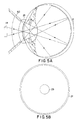
- the entrance pupil of the optical system (as relayed) is set at the eye lens to minimize aberrations and optimize rejection of scattered light; see Figure 1a.
- the minimum diameter and the slope of the edge of the contact lens are then set by the entrance pupil and the distance to the cornea and the FOV, as shown in Figure 1a.
- the minimum 6 mm diameter and the slope of the edge is 45 degree.
- the fiber ring F must set at a radius slightly larger, for example, 7 mm, and, in this design, its angle of injection is set to 45 degree by the slope of the contact lens L at this radius.
- the designer of a contact wide FOV camera faces a serious dilemma.
- the illumination ring is forced to be at a larger radius at this radius the human iris can occlude the portions of the illumination needed for the center of the retina.
- a dark spot can be seen if the patient's iris is not dilated large enough.
- an eye imaging portable image capture unit having a housing, a light source providing light in the housing for transmittal to an eye, imaging and focusing optics in the housing having a corneal contact lens for receiving reflected light from the eye through the cornea, an array image sensor in the housing for receiving light from the eye through the imaging and focusing optics in the housing, and a circular light guide positioned in the housing and positioned behind the corneal contact lens, said light guide including a solid one piece ring with a front end and a back end, said front end positioned at an angle converging inwardly and positioned adjacent the corneal contact lens, and said back end positioned to receive light from the light source.
- the object of the present invention is to provide a small, light weight, hand-held image capture unit (ICU).
- the ICU of the present invention contacts the retina, re-images the pupil, provides for wide field-of-view with minimal field curvature and minimized aberrations, and provides chromatic imaging with high fidelity.
- the advent of miniature three chip charged couple device (CCD) cameras which can be contained within the ICU increases the resolution of the image.
- CCD three chip charged couple device
- a specific objective of the present invention is to provide a wide field imaging unit that obtains high quality color images over 120 degrees and larger and this with highly uniform intensity of image, with low backscatter and a low-cost manufacturable design. It is also an objective to reduce the required minimum diameter of the dilated eye iris being 5.5mm, a figure commonly found among children. Further, it is an objective to provide an imaging unit that is light weight and can be hand-held. In another embodiment, the imaging unit allows for easy insertion and removal of various light filters for angiography and allows for easy insertion and removal of lenses.
- the present invention instead is directed to a portable image capture unit that provides for a one piece ring light guide made from machined plastic or ground and polished glass.
- the light guide is angled so that there is minimal back reflection from the eye lens to lessen the contrast of the image.
- a larger contact lens is used to lie between the imaging and illuminating optics to protect the cornea and this allows a vast improvement in the system performance as well as its manufacturability.
- Another feature of the present invention is to provide various improvements directing more light from the light guide onto the center of the retina of the eye.
- a light guide is fabricated from a transmissive material such as plastic or glass. Any satisfactory plastic may be used such as acrylic or polycarbonate and any satisfactory glass may be used such as an optical material with high transmittance (spectrum from 450 nm to 700 nm). If the light guide is surrounded by air, the divergence angle of light injected from the light guide is controllable and can be as wide as 180 degrees.
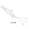
- a conceptional light delivery device shown in Fig.2a, is designed to concentrate the light from a larger diameter tube of light guide 50 to a small ring of light guide surrounding the front lens. As shown in Figure 2b, the end of the light guide can be shaped and the light be bent to aim in a more optimal direction.
- the sharp end 57 of the guide 50 is unacceptable when touching the cornea.
- the cavities around the end of the guide 50 will be places where germs can lodge and cross-contamination between patients would be inevitable.
- the tear film will fill in this volume and since the tear film has an index of refraction close to most waveguide materials, the ray bending at the end of the guide which occurs when the guide is surrounded by air (index nearly equal to 1) would be nearly eliminated (tear film index is close to 1.34) As the result, the dark spot will reappear in the center of image.
- the diameter of eye iris has to be dilated to be larger than 6.5 mm to prevent the blocking with a fiber ring of 6 mm diameter.
- the light intensity distribution on the retina is also designed so that the intensity increases gradually from the center to the periphery, which will result in a more uniform intensity distribution for the image of retina.
- the boundary of the "contact" glass will be bonded to the case protecting the volume behind the contact lens from any incursion of eye fluids or bonding agents.
- the contact lens 24 need not have any optical power, but it may if desired. The only bonding compound necessary will bond the edge of the contact lens 24 to the case 11 of the handpiece 10.
- the light guide and the imaging system are carefully designed so that the reflected light can not reach the CCD camera directly, it can still cause strong stray light which can degrade the image quality when a dark object like retina is imaged.
- a hard, durable conventional optical antireflection coating may be added to the front surface of contact glass.
- other measures which include selectively adding absorption layer to portion of light guide surface, installing a light stop in the imaging system, can be taken to reduce the stray light.
- the contact lens may have additional shape including a hole through which the front doublet can be mounted. The edge of the doublet is blacked so that the light traveling in the contact lens from the light guide can not enter the front doublet.
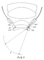
- the guide 50 has an end 51 with an angular cut which serves the function of directing the light through the contact lens 24 and towards the center of the eye E.
- the cornea contact glass lens 24 has essentially no power as the lens 24 is shown with the same radius of curvature on the front and on the back.
- the cornea contact glass lens 124 is provided with a power to provide assistance in directing the light from the end 151 of the light guide 150 towards the center of the eye E.
- the lens 124 may be a plano-concave lens with a more planar back 101 and a concave front 102.
- the second part 103 of the front lens 125 can be made of the same glass as the lens 124 and since it contacts the back surface 101 of the lens 124 the power of the back surface 101 of the lens 124 does not matter in the optical system.
- FIG. 7 A still more preferred embodiment is shown in Figures 7 and 8.
- the exit point from the end 151 of the light guide 150 is still moved outward from the center of the optical system by the required slope on the lens 103.
- an additional lens 205 is positioned between the light guide 250 and the cornea contact lens 224 for additionally directing the light towards the center of the eye E.
- a Fresnel lens 206 (Fig. 8) has been found satisfactory.
- the end 251 of the light guide 250 is extended downwardly into contact with the additional lens 205.
- the lens 205 could be placed on the end 251 of the light guide 250. This embodiment moves the source point for the light as far inward as is physically possible and is a relatively inexpensive design to fabricate.
- the present invention provides a wide field image capture unit (ICU) using the light guide of Figures 3, 5a, 6 and 7 to obtain high quality color images with a very wide FOV typically at 120 to 150 degrees. It is light weight and can be hand-held. However, it could be mounted on a slit-lamp like apparatus as well, perhaps an ideal approach for cooperative adult patients.
- the ICU of the present invention further allows for easy insertion and removal of various light filters for angiography and/or different lenses or lens sets for varying FOV. Further, it is configured so that a lens set can be provided for imaging the front of the eye.
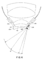
- FIG. 10 A preferred embodiment of the ICU of the present invention is shown in Figure 6.
- the reference numeral 10 indicates generally the image capture unit (ICU) of the present invention.
- the ICU has a front housing 11 and a rear housing 12 which separate at the junction 16 which in general may be for example a locking thread. Located in the rear housing 12 are connectors for fiber optics power delivery 17 and for camera and control functions, all of which is shown in WO 9 615 712.
- the portable ICU may be held in the hand to be touched to the cornea. Focusing is accomplished thorough an internal mechanism which varies the distance between the front and rear lens sets. Alternatively, a light source may be mounted in the ICU eliminating the requirement for the external light delivery fiber optics cable.
- the lens systems are divided into a front and rear set to accommodate focusing and pupil relaying functions.
- the front lens set 20 is comprised of a front doublet 25 with a wider contact or cornea lens 24 bonded onto the front and delivered to the system as a triplet.
- the next lens is a doublet 26 and then a singlet 27 followed by a meniscus 23 which may alternatively be an asphere to complete the front lens let.
- the rear lens set 30 is a doublet 31 and a triplet 32 for color aberration preventing means.
- a chromatic charged coupled device 38 is positioned to receive the retina image.
- the retina 40 is the object for the optical system and is re-imaged at image location 42 and then at the camera at image plane location 44.
- the system pupil is set by a mask at location 43 but is relayed to the eye lens at entrance pupil location 41.
- the light guide 50 is positioned behind the corneal contact lens 24 so as to illuminate the eye through the cornea and has a shaped tip 51.
- a field stop is set by a mask at location 45 to define 120 degree FOV and block stray light.
- a stray light stop is set by a mask at location 46 to further block light reflected from the front lens.
- Connecting cables between the ICU and the other components of a complete eye imaging device includes a control line for supplying and receiving information between the ICU and the other components, and an electrical cable for supplying power to the ICU all as disclosed in WO-A-9 615 712.
- a light fiber optic cable 13 for supplying light from a light source outside the capture unit is included in the control line.
- a one-piece, solid ring is used as a light guide 50.
- the guide 50 may consist of extensions 50a and 50b which abut each other for light transfer.
- the tip 51 is shaped to bend the light to desired direction.
- a light absorption layer is coated on the selected portion of surface to reduce the stray light.
- Using a transparent light guide made as a ring from a single piece of plastic or glass has great advantages.
- the angle from which the light is aimed from the fiber is controlled by the location of the fiber on the radius of the cornea and is the normal to the cornea at the location of the ring.
- light is fed to the ICU 10 through a light fiber optic cable 13, which is contained in the connecting cable.
- the light fiber optic cable brings light to the ICU from a light source located in another component of an entire imaging device outside the ICU. In another embodiment, a light source is completely contained within the ICU 10.
- the present invention provides a split housing 11 and 12 for the ICU 10 to allow for changing the front lens set 20 to accommodate different sizes and contours of the eye. For example, a different corneal contact lens 24 would be appropriate for an infant, as opposed to the corneal lens used on an adult. Further, it is a particular feature of the present invention that the front and rear lens sets 20 and 30 may be changed or re-positioned quickly and easily to accommodate insertion of filters 70 for various fluorescent angiographies or to accommodate lenses which provide different fields-of-view. A simple contact 71 between the front and rear sections 11 and 12 of the ICU 10 is sufficient for illumination transfer.
- the split housing makes it possible to remove the front lens set 20 completely, using the rear lens set 30 alone to image the front of the eye.
- a further advantage of providing a split housing 11 is if the front housing is removed and then a special housing 60, as best seen in Figure 12, inserted in its place which is designed to image the front of the eye through lens 61.
- the light already provided to the rear housing can be directed to a diffuser 62 which can then provide the illumination for the corneal image.
- the retinal camera can do double duty as a corneal imager.
Landscapes
- Health & Medical Sciences (AREA)
- Life Sciences & Earth Sciences (AREA)
- Engineering & Computer Science (AREA)
- Medical Informatics (AREA)
- Surgery (AREA)
- Biophysics (AREA)
- Biomedical Technology (AREA)
- Heart & Thoracic Surgery (AREA)
- Physics & Mathematics (AREA)
- Molecular Biology (AREA)
- Ophthalmology & Optometry (AREA)
- Animal Behavior & Ethology (AREA)
- General Health & Medical Sciences (AREA)
- Public Health (AREA)
- Veterinary Medicine (AREA)
- Multimedia (AREA)
- Eye Examination Apparatus (AREA)
- Studio Devices (AREA)
- Medical Preparation Storing Or Oral Administration Devices (AREA)
Applications Claiming Priority (5)
| Application Number | Priority Date | Filing Date | Title |
|---|---|---|---|
| US68572596A | 1996-07-24 | 1996-07-24 | |
| US685725 | 1996-07-24 | ||
| US08/820,224 US5822036A (en) | 1996-07-24 | 1997-03-18 | Eye imaging unit having a circular light guide |
| US820224 | 1997-03-18 | ||
| PCT/US1997/012732 WO1998003112A1 (en) | 1996-07-24 | 1997-07-22 | Portable imaging capture unit for the eye |
Publications (3)
| Publication Number | Publication Date |
|---|---|
| EP0925013A1 EP0925013A1 (en) | 1999-06-30 |
| EP0925013A4 EP0925013A4 (en) | 1999-12-08 |
| EP0925013B1 true EP0925013B1 (en) | 2004-06-09 |
Family
ID=27103665
Family Applications (1)
| Application Number | Title | Priority Date | Filing Date |
|---|---|---|---|
| EP97935037A Expired - Lifetime EP0925013B1 (en) | 1996-07-24 | 1997-07-22 | Portable imaging capture unit for the eye |
Country Status (13)
| Country | Link |
|---|---|
| US (1) | US5822036A (enExample) |
| EP (1) | EP0925013B1 (enExample) |
| JP (1) | JP4141503B2 (enExample) |
| CN (1) | CN1157152C (enExample) |
| AT (1) | ATE268563T1 (enExample) |
| AU (1) | AU3806897A (enExample) |
| CA (1) | CA2260800C (enExample) |
| DE (1) | DE69729459T2 (enExample) |
| DK (1) | DK0925013T3 (enExample) |
| ES (1) | ES2218694T3 (enExample) |
| PT (1) | PT925013E (enExample) |
| TW (1) | TW352334B (enExample) |
| WO (1) | WO1998003112A1 (enExample) |
Families Citing this family (58)
| Publication number | Priority date | Publication date | Assignee | Title |
|---|---|---|---|---|
| US6012814A (en) * | 1998-05-28 | 2000-01-11 | University Of New Mexico | Extraocular muscle tester |
| DE29819341U1 (de) * | 1998-10-29 | 1999-03-04 | Oculus Optikgeräte GmbH, 35582 Wetzlar | Optisches System zur Beobachtung und zum Fotografieren des Augeninneren |
| AUPQ762500A0 (en) * | 2000-05-19 | 2000-06-15 | Lions Eye Institute Limited | Portable slit lamp |
| US6361167B1 (en) * | 2000-06-13 | 2002-03-26 | Massie Research Laboratories, Inc. | Digital eye camera |
| US20030086064A1 (en) * | 2001-11-06 | 2003-05-08 | Sutter Erich E | Head mounted infrared fundus illuminator |
| WO2003039355A1 (en) * | 2001-11-07 | 2003-05-15 | Darren Rich | Gonioscopy assembly |
| JP2003279705A (ja) * | 2002-03-25 | 2003-10-02 | Sanyo Electric Co Ltd | 反射防止部材 |
| JP4018425B2 (ja) * | 2002-03-29 | 2007-12-05 | 松下電器産業株式会社 | 目画像撮像装置 |
| WO2007109337A2 (en) * | 2006-03-21 | 2007-09-27 | Freedom Scientific, Inc. | Pdt magnifier camera illumination |
| US7621638B2 (en) * | 2006-11-29 | 2009-11-24 | Clarity Medical Systems, Inc. | Delivering a short Arc lamp light for eye imaging |
| DE102007014703A1 (de) * | 2007-03-23 | 2008-09-25 | Dieter Mann Gmbh | Diaphanoskopstab |
| CN101474061B (zh) * | 2008-01-03 | 2011-07-20 | 北京宏仁凝瑞科技发展有限公司 | 一种接触式眼底成像系统 |
| US20100091244A1 (en) * | 2008-07-19 | 2010-04-15 | Volk Donald A | Real image forming eye examination lens utilizing two reflecting surfaces with non-mirrored central viewing area |
| US8786520B2 (en) * | 2008-09-04 | 2014-07-22 | Innovega, Inc. | System and apparatus for display panels |
| US8070290B2 (en) * | 2008-12-17 | 2011-12-06 | Glaukos Corporation | Gonioscope for improved viewing |
| US8740383B2 (en) | 2009-05-06 | 2014-06-03 | University Of Virginia Patent Foundation | Self-illuminated handheld lens for retinal examination and photography and related method thereof |
| US8836778B2 (en) | 2009-12-04 | 2014-09-16 | Lumetrics, Inc. | Portable fundus camera |
| USD645489S1 (en) | 2009-12-16 | 2011-09-20 | Glaukos Corporation | Gonioscopic system including an optical element attachment |
| USD645490S1 (en) | 2009-12-16 | 2011-09-20 | Glaukos Corporation | Gonioscopic system including an optical element attachment |
| ITTN20100008U1 (it) * | 2010-05-27 | 2011-11-28 | Gianfranco Passuello | Lacrimoscopio con tecnologia leds |
| WO2012018991A2 (en) | 2010-08-05 | 2012-02-09 | Bioptigen, Inc. | Compact multimodality optical coherence tomography imaging systems and related methods and computer program products |
| US20150021228A1 (en) | 2012-02-02 | 2015-01-22 | Visunex Medical Systems Co., Ltd. | Eye imaging apparatus and systems |
| US9655517B2 (en) | 2012-02-02 | 2017-05-23 | Visunex Medical Systems Co. Ltd. | Portable eye imaging apparatus |
| US9179840B2 (en) * | 2012-03-17 | 2015-11-10 | Visunex Medical Systems Co. Ltd. | Imaging and lighting optics of a contact eye camera |
| US9351639B2 (en) | 2012-03-17 | 2016-05-31 | Visunex Medical Systems Co. Ltd. | Eye imaging apparatus with a wide field of view and related methods |
| US9642606B2 (en) | 2012-06-27 | 2017-05-09 | Camplex, Inc. | Surgical visualization system |
| US10022041B2 (en) | 2012-06-27 | 2018-07-17 | Camplex, Inc. | Hydraulic system for surgical applications |
| WO2014066777A1 (en) * | 2012-10-25 | 2014-05-01 | The Regents Of The University Of Colorado, A Body Corporate | Adjustable loop fiber optic illumination device for surgery |
| USD717856S1 (en) | 2013-03-01 | 2014-11-18 | Welch Allyn, Inc. | Optical device adapter |
| WO2014189969A1 (en) | 2013-05-21 | 2014-11-27 | Camplex, Inc. | Surgical visualization systems |
| US9907698B2 (en) * | 2013-06-25 | 2018-03-06 | TECLens, LLC | Apparatus for phototherapy of the eye |
| WO2015042483A2 (en) | 2013-09-20 | 2015-03-26 | Camplex, Inc. | Surgical visualization systems |
| EP3047326A4 (en) | 2013-09-20 | 2017-09-06 | Camplex, Inc. | Surgical visualization systems and displays |
| US9986908B2 (en) | 2014-06-23 | 2018-06-05 | Visunex Medical Systems Co. Ltd. | Mechanical features of an eye imaging apparatus |
| WO2016004385A1 (en) * | 2014-07-02 | 2016-01-07 | IDx, LLC | Systems and methods for alignment of the eye for ocular imaging |
| US10258232B2 (en) | 2014-09-14 | 2019-04-16 | Retivue Llc | Wide field fundus camera |
| EP3197340B1 (en) | 2014-09-26 | 2018-11-07 | Volk Optical, Inc. | Ophthalmic lens assemblies and methods of assembly and use |
| WO2016090336A1 (en) | 2014-12-05 | 2016-06-09 | Camplex, Inc. | Surgical visualization systems and displays |
| CN104398236B (zh) * | 2014-12-17 | 2015-12-16 | 天津市索维电子技术有限公司 | 一种大视场眼底成像装置 |
| WO2016123138A1 (en) | 2015-01-26 | 2016-08-04 | Visunex Medical Systems Co. Ltd. | A disposable cap for an eye imaging apparatus and related methods |
| CA2980289C (en) | 2015-03-20 | 2024-05-14 | Glaukos Corporation | Gonioscopic devices |
| US11154378B2 (en) | 2015-03-25 | 2021-10-26 | Camplex, Inc. | Surgical visualization systems and displays |
| JP7075178B2 (ja) | 2015-08-05 | 2022-05-25 | フェニックス テクノロジー グループ インコーポレイテッド | 広視野の網膜イメージャおよびその動作方法 |
| US10966798B2 (en) | 2015-11-25 | 2021-04-06 | Camplex, Inc. | Surgical visualization systems and displays |
| GB201520983D0 (en) * | 2015-11-27 | 2016-01-13 | Univ Strathclyde | Imaging system and method |
| CN105662332A (zh) * | 2016-04-13 | 2016-06-15 | 南京航空航天大学 | 一种环形照明的广角眼底视网膜成像装置及方法 |
| EP3454719A1 (en) * | 2016-05-13 | 2019-03-20 | Ecole Polytechnique Federale de Lausanne (EPFL) | System, method and apparatus for retinal absorption phase and dark field imaging with oblique illumination |
| WO2017223208A1 (en) | 2016-06-21 | 2017-12-28 | Retivue, Llc | Wide field fundus camera with auto-montage at a single alignment |
| US10674906B2 (en) | 2017-02-24 | 2020-06-09 | Glaukos Corporation | Gonioscopes |
| USD833008S1 (en) | 2017-02-27 | 2018-11-06 | Glaukos Corporation | Gonioscope |
| US10918455B2 (en) | 2017-05-08 | 2021-02-16 | Camplex, Inc. | Variable light source |
| EP3681373B1 (en) * | 2017-12-19 | 2025-03-26 | Alcon Inc. | Imaging multiple parts of the eye |
| CN113507879B (zh) | 2018-10-13 | 2025-04-01 | 普瑞文塔医疗公司 | 用于改善眼部诊断、疾病管理和手术的照明接触镜和系统 |
| CN113520302A (zh) * | 2019-01-30 | 2021-10-22 | 北京大学第三医院(北京大学第三临床医学院) | 一种眼科拍照方法 |
| US11426071B2 (en) | 2019-10-10 | 2022-08-30 | Natus Medical Incorporated | Eye-imaging system and apparatus |
| CN110974154A (zh) * | 2019-10-31 | 2020-04-10 | 中山联合光电科技股份有限公司 | 一种接触式眼底相机照明系统 |
| CN113509142B (zh) * | 2021-06-07 | 2023-06-02 | 天津市索维电子技术有限公司 | 一种大视野视网膜检查装置 |
| CN115191927B (zh) * | 2022-06-02 | 2025-04-04 | 北京理工大学 | 一种测量人眼角膜曲率的紧凑型光学系统 |
Family Cites Families (13)
| Publication number | Priority date | Publication date | Assignee | Title |
|---|---|---|---|---|
| US3630602A (en) * | 1970-05-04 | 1971-12-28 | John Frederick Herbert | Contact lens |
| US4200362A (en) * | 1972-09-25 | 1980-04-29 | Retina Foundation | Ophthalmoscope with uniform illumination |
| US3954329A (en) * | 1972-09-25 | 1976-05-04 | Retina Foundation | Wide-angle opthalmoscope employing transillumination |
| US3944341A (en) * | 1972-09-25 | 1976-03-16 | Retina Foundation | Wide-angle ophthalmoscope and fundus camera |
| US4023189A (en) * | 1974-03-29 | 1977-05-10 | Varian Associates | Wide angle fundus illumination and photography apparatus |
| US4026638A (en) * | 1974-12-02 | 1977-05-31 | Varian Associates | Reduced glare scanner |
| DE2716614C3 (de) * | 1977-04-15 | 1980-10-16 | Fa. Carl Zeiss, 7920 Heidenheim | Optisches System zur Abbildung der Netzhaut |
| US4715703A (en) * | 1982-10-12 | 1987-12-29 | Rodenstock Instrument Corporation | Ocular-fundus analyzer |
| US4573778A (en) * | 1983-03-16 | 1986-03-04 | Boston University | Aqueous fluorophotometer |
| US5125730A (en) * | 1990-06-29 | 1992-06-30 | The United States Of America As Represented By The Administrator Of The National Aeronautics And Space Administration | Portable dynamic fundus instrument |
| DE4232280A1 (de) * | 1992-09-25 | 1994-03-31 | Optec Ges Fuer Optische Techni | Retinoskop mit Lichtleiterbeleuchtung |
| US5608472A (en) * | 1992-11-06 | 1997-03-04 | Research Development Foundation | Eye imaging system |
| US5537164A (en) * | 1994-12-20 | 1996-07-16 | Smith; Alan D. | Retroilluminating indirect gonioprism |
-
1997
- 1997-03-18 US US08/820,224 patent/US5822036A/en not_active Expired - Lifetime
- 1997-06-14 TW TW086108277A patent/TW352334B/zh not_active IP Right Cessation
- 1997-07-22 PT PT97935037T patent/PT925013E/pt unknown
- 1997-07-22 EP EP97935037A patent/EP0925013B1/en not_active Expired - Lifetime
- 1997-07-22 AT AT97935037T patent/ATE268563T1/de active
- 1997-07-22 WO PCT/US1997/012732 patent/WO1998003112A1/en not_active Ceased
- 1997-07-22 CA CA002260800A patent/CA2260800C/en not_active Expired - Lifetime
- 1997-07-22 JP JP50716198A patent/JP4141503B2/ja not_active Expired - Lifetime
- 1997-07-22 AU AU38068/97A patent/AU3806897A/en not_active Abandoned
- 1997-07-22 ES ES97935037T patent/ES2218694T3/es not_active Expired - Lifetime
- 1997-07-22 DE DE69729459T patent/DE69729459T2/de not_active Expired - Lifetime
- 1997-07-22 CN CNB971967024A patent/CN1157152C/zh not_active Expired - Lifetime
- 1997-07-22 DK DK97935037T patent/DK0925013T3/da active
Also Published As
| Publication number | Publication date |
|---|---|
| DE69729459T2 (de) | 2005-06-30 |
| JP2002500520A (ja) | 2002-01-08 |
| AU3806897A (en) | 1998-02-10 |
| US5822036A (en) | 1998-10-13 |
| DE69729459D1 (de) | 2004-07-15 |
| PT925013E (pt) | 2004-10-29 |
| ATE268563T1 (de) | 2004-06-15 |
| CA2260800A1 (en) | 1998-01-29 |
| CN1157152C (zh) | 2004-07-14 |
| CA2260800C (en) | 2005-01-04 |
| JP4141503B2 (ja) | 2008-08-27 |
| ES2218694T3 (es) | 2004-11-16 |
| EP0925013A1 (en) | 1999-06-30 |
| EP0925013A4 (en) | 1999-12-08 |
| DK0925013T3 (da) | 2004-07-26 |
| TW352334B (en) | 1999-02-11 |
| WO1998003112A1 (en) | 1998-01-29 |
| CN1226143A (zh) | 1999-08-18 |
Similar Documents
| Publication | Publication Date | Title |
|---|---|---|
| EP0925013B1 (en) | Portable imaging capture unit for the eye | |
| US9179840B2 (en) | Imaging and lighting optics of a contact eye camera | |
| US9907468B2 (en) | Eye imaging apparatus with sequential illumination | |
| US11857261B2 (en) | Eye-imaging system and apparatus with coordinated illuminator fibers having a skewed fiber angle | |
| CN100477977C (zh) | 用于连接激光加工装置和物体的适配器 | |
| US20100091244A1 (en) | Real image forming eye examination lens utilizing two reflecting surfaces with non-mirrored central viewing area | |
| US20040254424A1 (en) | Integrated panoramic and forward view endoscope | |
| US7144111B1 (en) | Ophthalmoscopy lens system | |
| JP2010063485A (ja) | 内視鏡用照明光学系及び内視鏡 | |
| JPH07255771A (ja) | 眼科治療及び/又は診断機器用の安全フィルタ並びにそのためのレーザアダプタ | |
| US10779727B2 (en) | Lens system for inspection of an eye | |
| CN213097817U (zh) | 一种可更换镜头的手持式数字诊断系统 | |
| JP3660720B2 (ja) | 内視鏡用接眼装置 | |
| KR20030087455A (ko) | 안구 유도가 가능한 안구 촬영용 광학장치 |
Legal Events
| Date | Code | Title | Description |
|---|---|---|---|
| PUAI | Public reference made under article 153(3) epc to a published international application that has entered the european phase |
Free format text: ORIGINAL CODE: 0009012 |
|
| 17P | Request for examination filed |
Effective date: 19990122 |
|
| AK | Designated contracting states |
Kind code of ref document: A1 Designated state(s): AT BE CH DE DK ES FI FR GB GR IE IT LI NL PT SE |
|
| A4 | Supplementary search report drawn up and despatched |
Effective date: 19991026 |
|
| AK | Designated contracting states |
Kind code of ref document: A4 Designated state(s): AT BE CH DE DK ES FI FR GB GR IE IT LI NL PT SE |
|
| RIC1 | Information provided on ipc code assigned before grant |
Free format text: 6A 61B 3/10 A, 6A 61B 3/00 B, 6A 61B 3/125 B, 6A 61B 3/14 B |
|
| 17Q | First examination report despatched |
Effective date: 20030603 |
|
| RIC1 | Information provided on ipc code assigned before grant |
Ipc: 7A 61B 3/14 B Ipc: 7A 61B 3/125 B Ipc: 7A 61B 3/00 B Ipc: 7A 61B 3/10 A |
|
| RIC1 | Information provided on ipc code assigned before grant |
Ipc: 7A 61B 3/14 B Ipc: 7A 61B 3/125 B Ipc: 7A 61B 3/00 B Ipc: 7A 61B 3/10 A |
|
| GRAP | Despatch of communication of intention to grant a patent |
Free format text: ORIGINAL CODE: EPIDOSNIGR1 |
|
| GRAS | Grant fee paid |
Free format text: ORIGINAL CODE: EPIDOSNIGR3 |
|
| GRAA | (expected) grant |
Free format text: ORIGINAL CODE: 0009210 |
|
| AK | Designated contracting states |
Kind code of ref document: B1 Designated state(s): AT BE CH DE DK ES FI FR GB GR IE IT LI NL PT SE |
|
| REG | Reference to a national code |
Ref country code: GB Ref legal event code: FG4D |
|
| REG | Reference to a national code |
Ref country code: CH Ref legal event code: EP |
|
| REG | Reference to a national code |
Ref country code: SE Ref legal event code: TRGR |
|
| REF | Corresponds to: |
Ref document number: 69729459 Country of ref document: DE Date of ref document: 20040715 Kind code of ref document: P |
|
| REG | Reference to a national code |
Ref country code: DK Ref legal event code: T3 |
|
| REG | Reference to a national code |
Ref country code: IE Ref legal event code: FG4D |
|
| REG | Reference to a national code |
Ref country code: CH Ref legal event code: NV Representative=s name: ISLER & PEDRAZZINI AG |
|
| REG | Reference to a national code |
Ref country code: GR Ref legal event code: EP Ref document number: 20040402823 Country of ref document: GR |
|
| REG | Reference to a national code |
Ref country code: PT Ref legal event code: SC4A Free format text: AVAILABILITY OF NATIONAL TRANSLATION Effective date: 20040908 |
|
| REG | Reference to a national code |
Ref country code: ES Ref legal event code: FG2A Ref document number: 2218694 Country of ref document: ES Kind code of ref document: T3 |
|
| ET | Fr: translation filed | ||
| PLBE | No opposition filed within time limit |
Free format text: ORIGINAL CODE: 0009261 |
|
| STAA | Information on the status of an ep patent application or granted ep patent |
Free format text: STATUS: NO OPPOSITION FILED WITHIN TIME LIMIT |
|
| 26N | No opposition filed |
Effective date: 20050310 |
|
| REG | Reference to a national code |
Ref country code: CH Ref legal event code: PCAR Free format text: ISLER & PEDRAZZINI AG;POSTFACH 1772;8027 ZUERICH (CH) |
|
| REG | Reference to a national code |
Ref country code: FR Ref legal event code: PLFP Year of fee payment: 20 |
|
| PGFP | Annual fee paid to national office [announced via postgrant information from national office to epo] |
Ref country code: ES Payment date: 20160613 Year of fee payment: 20 Ref country code: GR Payment date: 20160614 Year of fee payment: 20 |
|
| PGFP | Annual fee paid to national office [announced via postgrant information from national office to epo] |
Ref country code: BE Payment date: 20160524 Year of fee payment: 20 Ref country code: FR Payment date: 20160613 Year of fee payment: 20 |
|
| PGFP | Annual fee paid to national office [announced via postgrant information from national office to epo] |
Ref country code: NL Payment date: 20160711 Year of fee payment: 20 |
|
| PGFP | Annual fee paid to national office [announced via postgrant information from national office to epo] |
Ref country code: DE Payment date: 20160720 Year of fee payment: 20 Ref country code: DK Payment date: 20160712 Year of fee payment: 20 Ref country code: CH Payment date: 20160712 Year of fee payment: 20 Ref country code: IE Payment date: 20160711 Year of fee payment: 20 Ref country code: IT Payment date: 20160720 Year of fee payment: 20 Ref country code: GB Payment date: 20160720 Year of fee payment: 20 Ref country code: FI Payment date: 20160711 Year of fee payment: 20 |
|
| PGFP | Annual fee paid to national office [announced via postgrant information from national office to epo] |
Ref country code: PT Payment date: 20160722 Year of fee payment: 20 Ref country code: SE Payment date: 20160712 Year of fee payment: 20 Ref country code: AT Payment date: 20160630 Year of fee payment: 20 |
|
| REG | Reference to a national code |
Ref country code: DE Ref legal event code: R071 Ref document number: 69729459 Country of ref document: DE |
|
| REG | Reference to a national code |
Ref country code: DK Ref legal event code: EUP Effective date: 20170722 |
|
| REG | Reference to a national code |
Ref country code: NL Ref legal event code: MK Effective date: 20170721 |
|
| REG | Reference to a national code |
Ref country code: CH Ref legal event code: PL |
|
| REG | Reference to a national code |
Ref country code: GB Ref legal event code: PE20 Expiry date: 20170721 |
|
| REG | Reference to a national code |
Ref country code: IE Ref legal event code: MK9A |
|
| REG | Reference to a national code |
Ref country code: AT Ref legal event code: MK07 Ref document number: 268563 Country of ref document: AT Kind code of ref document: T Effective date: 20170722 |
|
| REG | Reference to a national code |
Ref country code: BE Ref legal event code: MK Effective date: 20170722 |
|
| PG25 | Lapsed in a contracting state [announced via postgrant information from national office to epo] |
Ref country code: GB Free format text: LAPSE BECAUSE OF EXPIRATION OF PROTECTION Effective date: 20170721 Ref country code: PT Free format text: LAPSE BECAUSE OF EXPIRATION OF PROTECTION Effective date: 20170801 Ref country code: IE Free format text: LAPSE BECAUSE OF EXPIRATION OF PROTECTION Effective date: 20170722 |
|
| REG | Reference to a national code |
Ref country code: ES Ref legal event code: FD2A Effective date: 20180508 |
|
| PG25 | Lapsed in a contracting state [announced via postgrant information from national office to epo] |
Ref country code: ES Free format text: LAPSE BECAUSE OF EXPIRATION OF PROTECTION Effective date: 20170723 |