EP0924977B2 - A machine for spreading materials in granular and/or powder form, particularly fertilizers - Google Patents
A machine for spreading materials in granular and/or powder form, particularly fertilizers Download PDFInfo
- Publication number
- EP0924977B2 EP0924977B2 EP97940154A EP97940154A EP0924977B2 EP 0924977 B2 EP0924977 B2 EP 0924977B2 EP 97940154 A EP97940154 A EP 97940154A EP 97940154 A EP97940154 A EP 97940154A EP 0924977 B2 EP0924977 B2 EP 0924977B2
- Authority
- EP
- European Patent Office
- Prior art keywords
- hopper
- outlet
- spreading
- relative
- along
- Prior art date
- Legal status (The legal status is an assumption and is not a legal conclusion. Google has not performed a legal analysis and makes no representation as to the accuracy of the status listed.)
- Expired - Lifetime
Links
Images


Classifications
-
- A—HUMAN NECESSITIES
- A01—AGRICULTURE; FORESTRY; ANIMAL HUSBANDRY; HUNTING; TRAPPING; FISHING
- A01C—PLANTING; SOWING; FERTILISING
- A01C17/00—Fertilisers or seeders with centrifugal wheels
- A01C17/006—Regulating or dosing devices
Definitions
- the present invention relates to a machine for spreading materials in granular and/or powder form, according to the premble of claim 1.
- the invention was devised for use in the spreading of fertilizer. However, it is not limited to this use and may equally well be used in the spreading of salt, sand, rice, seeds and other mineral and chemical products, generally in granular or powder form.
- Machines having the characteristics indicated above are known in the specific field of land fertilization by the term "manure spreaders".
- the spreading device generally comprises a pair of disks which are rotated in opposite directions about parallel axes and onto which the fertilizer supplied from the hopper falls. The fertilizer is thus spread on the ground by the centrifugal effect caused by rapid rotation of the disks.
- Each disk also generally has one or more spreader blades.
- German patent application No. 4206301 describes a pivotable chute fitted on the bottom of the hopper for diverting at least some of the flow of material delivered by the hopper. This device serves for regulating the uniformity of spreading but has the disadvantage of achieving too coarse a regulation to ensure effective homogeneity of spreading.
- the problem upon which the present invention is based is that of providing a machine for spreading granular materials which is designed structurally and functionally to overcome all of the problems complained of with reference to the prior art cited.
- FR-A-1134277, DE-A-1217127 and EP-A-0379103 are also prior art to the present invention.
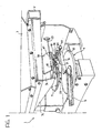
- FIG. 1 a machine formed in accordance with the present invention for spreading materials in granular and/or powder form, particularly fertilizers, is generally indicated 1.
- the machine 1 comprises a load-bearing structure 2 mounted on which are a hopper 3 for holding the fertilizer and a centrifugal spreading device 4 for spreading the fertilizer on the ground during the forward movement of the machine 1.
- the load-bearing structure 2 is provided with coupling elements, typically a three-point coupling, not shown, for coupling to a tractor or to a trailer.
- the hopper 3 comprises walls 3a-3d which are inclined so as to converge towards a base 3e of the hopper, closed by a plate 5.
- the plate 5 has a through-hole 6 constituting an outlet for the fertilizer held in the hopper 3.
- the machine 1 also comprises a device 10 for metering the flow of granular material discharged from the hopper 3 by falling.
- the metering device 10 comprises a substantially plate-shaped shutter 11 disposed against the plate 5.
- One end ofthe shutter 11 is mounted for pivoting on the plate 5 by means of a screw or pin 12 and its opposite end is articulated to a control rod 13.
- the shutter 11 is movable angularly in an adjustable manner by means of the rod 13 between a first position (shown in solid outline in Figure 4), in which the hole 6 in the hopper is completely shut off by the shutter, and a second position (shown in broken outline in Figure 4), in which the shutterdoes not shut off the hole 6, enabling the maximum flow of material to be delivered from the hopper 3.
- the spreading device 4 is mounted beneath the hopper 3 and comprises a pair of spreading disks 15 rotated in opposite directions about their respective axes. Only one of the spreading disks 15 is shown in Figures 1 to 3 but the machine 1 is intended to be equipped with a pair of identical disks 15, only one of which will be described below.
- the disk 15 is offset from the axis of the hole 6 and is mounted in a position such as to be struck by the fertilizer supplied by falling from the hopper 3. The fertilizer is thus spread on the ground as a result of the centrifugal effect brought about by the rotation of the disk 15.
- the disk 15 also has spreading blades 16 for guiding the granules of fertilizer on the trajectory on which they are expelled by the disc and thus ensuring more precise and uniform spreading.
- An outlet, generally indicated 20, for the fertilizer discharged from the hopper 3 is interposed between the base 3e of the hopper and the disk 15.
- the outlet 20 comprises a second, frusto-conical hopper 21 for collecting all of the material supplied by falling from the holding hopper 3.
- the second hopper 21 is fixed to a first support element including a first and a second bracket, indicated 23, 24, respectively.
- a first slot 25 is formed in the free end of the bracket 23 and the screw 12 is housed with clearance therein.
- the second bracket 24 has a second slot 26 which is of the same length as the slot 25 and is elongate in alignment with the slot 25 along an axis indicated A in Figure 5.
- the slot26 houses with clearance a pin 27 which in turn is housed in a third arcuate slot 28 formed in a second support element 30 fixed to the hopper 3.
- the slot 28 extends along an arc indicated B in Figure 5, centred on the axis of the pin 12.
- the axis A is selected in a manner such as to be substantially radial relative to the arc B.
- the outlet 20 is movable by means of the brackets 23, 24 along the axis A with the travel permitted by the length of the slots 25, 26 and, at the same time, is pivotable about the axis of the pin 12 with the angular travel permitted by the length of the arcuate slot 28.
- the position C in which the material falls can thus be selected within a surface area of the disk 15 defined by the travel permitted by the slots 25, 26 and 28.
- the second hopper 21 has dimensions such that it collects all of the material supplied from the holding hopper 3 in every adjustment position of the outlet 20 relative to the spreading disk 15.
- the travel permitted by the length of the slots 25 and 26 is about 40 mm and the angular travel permitted by the slot 28 is about 20°.
- the outlet 20 is shown in the limit positions imposed by the length ofthe slot 28 (in solid outline and broken outline, respectively) for a preselected positioning along the axis A.
- a knob 31, screwed onto the pin 27 in order to clamp the bracket 24 against the support element 30, is provided for locking the sliding and pivoting of the brackets 23, 24 and consequently of the outlet 20 relative to the hopper 3 once the preselected adjustment position has been reached.
- the outlet 20 is movable along the axis A by actuator means, generally indicated 35.
- the actuator means 35 comprise an L-shaped section 36 of which one flange is disposed against the bracket 24 and pivotable on the pin 27 and the other flange has a through-hole 37.
- the free end of the bracket 24 has an appendage 38 with a through-hole 39 coaxial with the hole 37.
- a nut 40 is fixed to the appendage 38 and is engaged by screwing on a threaded rod 41.
- the rod 41 is housed with radial clearance in the hole 37 and is damped axially relative to the section 36 by means of a pair of nuts indicated 42.
- a knob 44 is screwed onto one end of the rod 41. Rotation of the knob 41 causes relative sliding between the section 36 and the bracket 24 and consequently movement of the outlet along the radial axis A.
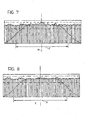
- Figures 7 and 8 are two graphs of fertilizer distribution in the form of histograms produced during two spreading tests carried out with the machine of the present invention.
- the distances on the ground from the axis of the machine, indicated X, are given on the abscissa.
- the working width of the machine, corresponding to the spreading width, is indicated Y.
- the quantities of fertilizer per unit of area treated achieved by the spreading at predetermined Intervals within the spreading width Y are given on the ordinate.
- the graph of Figure 8 was obtained with an adjustment of the position C in which the fertilizer falls onto the spreading device disk 15 achieved by movement of the outlet 20 along the axes A and B of Figure 5.
- the greater evenness of spreading in terms of uniformity of dosage of fertilizer per unit of area in comparison with the curve of graph 7 which, on the other hand, was obtained without any adjustment of the falling position C as described above can be seen.
- the uniformity of the distribution curve in the region of the axis of the machine X that is, in the overlapping zone in which the contributions of both spreading disks 15 to the spreading of the fertilize are added together, can be seen.
- the machine 1 will be equipped with tables for the correction of the position of the point at which the fertilizer falls in dependence on dosage values detected by the user, enabling the maximum possible uniformity and homogeneity of spreading to be achieved.
Landscapes
- Life Sciences & Earth Sciences (AREA)
- Soil Sciences (AREA)
- Environmental Sciences (AREA)
- Fertilizing (AREA)
- Fertilizers (AREA)
- Sowing (AREA)
- Pretreatment Of Seeds And Plants (AREA)
Abstract
Description
- The present invention relates to a machine for spreading materials in granular and/or powder form, according to the premble of
claim 1. - The invention was devised for use in the spreading of fertilizer. However, it is not limited to this use and may equally well be used in the spreading of salt, sand, rice, seeds and other mineral and chemical products, generally in granular or powder form.
- Machines having the characteristics indicated above are known in the specific field of land fertilization by the term "manure spreaders".
- In these machines, the spreading device generally comprises a pair of disks which are rotated in opposite directions about parallel axes and onto which the fertilizer supplied from the hopper falls. The fertilizer is thus spread on the ground by the centrifugal effect caused by rapid rotation of the disks. Each disk also generally has one or more spreader blades.
- In use, amongst the main requirements of spreading devices of the type indicated is that of ensuring maximum homogeneity, uniformity and evenness of the distribution of the fertilizer on the ground treated. These characteristics normally mean ensuring a predetermined dosage of fertilizer per unit of area, which has to be kept as constant as possible over the entire working width affected by the spreading. In particular, these spreading characteristics have to be ensured in the overlapping zones, that is, the zones which extend beside the working area of the spreading device and are subject to the spreading of fertilizer during both the outward and the return journey of the machine over the plot of land to be treated.
- German patent application No. 4206301 describes a pivotable chute fitted on the bottom of the hopper for diverting at least some of the flow of material delivered by the hopper. This device serves for regulating the uniformity of spreading but has the disadvantage of achieving too coarse a regulation to ensure effective homogeneity of spreading.
- The problem upon which the present invention is based is that of providing a machine for spreading granular materials which is designed structurally and functionally to overcome all of the problems complained of with reference to the prior art cited.
- FR-A-1134277, DE-A-1217127 and EP-A-0379103 are also prior art to the present invention.
- This problem is solved according to the invention by a machine formed in accordance with the following claims.
- The characteristics and advantages of the invention will become clearer from the detailed description of a preferred embodiment thereof, described by way of non-limiting example with reference to the appended drawings, in which:
- Figure 1 is a partial perspective view of a machine formed in accordance with the present invention,
- Figure 2 is a partially-sectioned, side elevational view of the machine of Figure 1,
- Figure 3 is a partially-sectioned plan view of the machine of the preceding drawings,
- Figures 4 and 5 show details of the machine of the preceding drawings, on an enlarged scale,
- Figure 6 is a sectioned view of a detail of the machine of Figure 1,
- Figures 7 and 8 are two fertilizer-distribution graphs.
- In Figure 1, a machine formed in accordance with the present invention for spreading materials in granular and/or powder form, particularly fertilizers, is generally indicated 1.
- The
machine 1 comprises a load-bearingstructure 2 mounted on which are ahopper 3 for holding the fertilizer and acentrifugal spreading device 4 for spreading the fertilizer on the ground during the forward movement of themachine 1. The load-bearingstructure 2 is provided with coupling elements, typically a three-point coupling, not shown, for coupling to a tractor or to a trailer. - The
hopper 3 comprises walls 3a-3d which are inclined so as to converge towards a base 3e of the hopper, closed by aplate 5. Theplate 5 has a through-hole 6 constituting an outlet for the fertilizer held in thehopper 3. Inside thehopper 3 there is astirrer 7 disposed adjacent the base 3e and rotated by means of a drive shaft 8. - Grids mounted inside the
hopper 3 are indicated 9. - The
machine 1 also comprises adevice 10 for metering the flow of granular material discharged from thehopper 3 by falling. Themetering device 10 comprises a substantially plate-shaped shutter 11 disposed against theplate 5. One end oftheshutter 11 is mounted for pivoting on theplate 5 by means of a screw orpin 12 and its opposite end is articulated to acontrol rod 13. Theshutter 11 is movable angularly in an adjustable manner by means of therod 13 between a first position (shown in solid outline in Figure 4), in which the hole 6 in the hopper is completely shut off by the shutter, and a second position (shown in broken outline in Figure 4), in which the shutterdoes not shut off the hole 6, enabling the maximum flow of material to be delivered from thehopper 3. - The spreading
device 4 is mounted beneath thehopper 3 and comprises a pair of spreadingdisks 15 rotated in opposite directions about their respective axes. Only one of the spreadingdisks 15 is shown in Figures 1 to 3 but themachine 1 is intended to be equipped with a pair ofidentical disks 15, only one of which will be described below. - The
disk 15 is offset from the axis of the hole 6 and is mounted in a position such as to be struck by the fertilizer supplied by falling from thehopper 3. The fertilizer is thus spread on the ground as a result of the centrifugal effect brought about by the rotation of thedisk 15. Thedisk 15 also has spreadingblades 16 for guiding the granules of fertilizer on the trajectory on which they are expelled by the disc and thus ensuring more precise and uniform spreading. - An outlet, generally indicated 20, for the fertilizer discharged from the
hopper 3 is interposed between the base 3e of the hopper and thedisk 15. Theoutlet 20 comprises a second, frusto-conical hopper 21 for collecting all of the material supplied by falling from theholding hopper 3. Thesecond hopper 21 is fixed to a first support element including a first and a second bracket, indicated 23, 24, respectively. Afirst slot 25 is formed in the free end of thebracket 23 and thescrew 12 is housed with clearance therein. Thesecond bracket 24 has asecond slot 26 which is of the same length as theslot 25 and is elongate in alignment with theslot 25 along an axis indicated A in Figure 5. The slot26 houses with clearance apin 27 which in turn is housed in a thirdarcuate slot 28 formed in asecond support element 30 fixed to thehopper 3. Theslot 28 extends along an arc indicated B in Figure 5, centred on the axis of thepin 12. The axis A is selected in a manner such as to be substantially radial relative to the arc B. In accordance with this structure, theoutlet 20 is movable by means of thebrackets slots pin 12 with the angular travel permitted by the length of thearcuate slot 28. The combination of the movements along the axes A and B, which belong to a system of polar coordinates, thus enables theoutlet 20 to be moved along intersecting axes relative to thedisk 15 so as to vary selectively, relative to thedisk 15, the position, indicated C in Figure 5, in which the material falls. The position C in which the material falls can thus be selected within a surface area of thedisk 15 defined by the travel permitted by theslots - It should be noted that the
second hopper 21 has dimensions such that it collects all of the material supplied from theholding hopper 3 in every adjustment position of theoutlet 20 relative to the spreadingdisk 15. - According to a preferred embodiment of the invention, the travel permitted by the length of the
slots slot 28 is about 20°. In Figure 5, theoutlet 20 is shown in the limit positions imposed by the length ofthe slot 28 (in solid outline and broken outline, respectively) for a preselected positioning along the axis A. - A
knob 31, screwed onto thepin 27 in order to clamp thebracket 24 against thesupport element 30, is provided for locking the sliding and pivoting of thebrackets outlet 20 relative to thehopper 3 once the preselected adjustment position has been reached. - According to a further characteristic of the invention, the
outlet 20 is movable along the axis A by actuator means, generally indicated 35. The actuator means 35 comprise an L-shaped section 36 of which one flange is disposed against thebracket 24 and pivotable on thepin 27 and the other flange has a through-hole 37. The free end of thebracket 24 has anappendage 38 with a through-hole 39 coaxial with thehole 37. A nut 40 is fixed to theappendage 38 and is engaged by screwing on a threadedrod 41. Therod 41 is housed with radial clearance in thehole 37 and is damped axially relative to the section 36 by means of a pair of nuts indicated 42. Aknob 44 is screwed onto one end of therod 41. Rotation of theknob 41 causes relative sliding between the section 36 and thebracket 24 and consequently movement of the outlet along the radial axis A. - Graduated
scales corresponding indicators - Figures 7 and 8 are two graphs of fertilizer distribution in the form of histograms produced during two spreading tests carried out with the machine of the present invention. The distances on the ground from the axis of the machine, indicated X, are given on the abscissa. The working width of the machine, corresponding to the spreading width, is indicated Y. The quantities of fertilizer per unit of area treated achieved by the spreading at predetermined Intervals within the spreading width Y are given on the ordinate.
- The graph of Figure 8 was obtained with an adjustment of the position C in which the fertilizer falls onto the spreading
device disk 15 achieved by movement of theoutlet 20 along the axes A and B of Figure 5. The greater evenness of spreading in terms of uniformity of dosage of fertilizer per unit of area in comparison with the curve ofgraph 7 which, on the other hand, was obtained without any adjustment of the falling position C as described above can be seen. In particular, the uniformity of the distribution curve in the region of the axis of the machine X, that is, in the overlapping zone in which the contributions of both spreadingdisks 15 to the spreading of the fertilize are added together, can be seen. - It should be noted that the adjustment which can be achieved with the machine of the invention in the point at which the material falls also achieves uniform and homogeneous spreading with granular materials of different particle size and specific weight.
- For use by the final user, it is envisaged that the
machine 1 will be equipped with tables for the correction of the position of the point at which the fertilizer falls in dependence on dosage values detected by the user, enabling the maximum possible uniformity and homogeneity of spreading to be achieved.
Claims (4)
- A machine for spreading materials in granular and/or powder form, particularly fertilizers, of the type comprising a hopper (3) for holding the material to spread, including an outlet (20) for the material and at least one centrifugal spreading device (4) mounted beneath the hopper (3), the outlet (20) being movable relative to the spreading device (4) in order to vary the position in which the material falls onto the spreading device (4) and consequently to adjust the parameters of the spreading of the material, the outlet (20) being movable relative to the spreading device along at least two intersecting axes (A, B), outlet positioning means being provided for moving the outlet (20) along said at least two axes (A, B), screw actuator means being operatively connected to said outlet-positioning means for moving said outlet along at least one of said axes (A, B) by rotation of said screw actuator means, characterized in that the axes (A, B) belong to a system of polar coordinates, said screw actuator means are operatively connected to said outlet-positioning means along the radial direction (A) of said system of polar coordinates, and said outlet-positioning means include first and second guide means (28, 25, 26), the first guide means (28) extending along an arc (B) centred on the second guide means (25, 26), the second guide means extending in said radial direction relative to the arc, for fine adjustment, with said screw actuator means, of the position in which the material falls on the spreading device.
- A machine according to claim 1, comprising a second hopper (21) which is disposed beneath the hopper (3) for holding the material and has dimensions such that it collects all of the material supplied by falling from the holding hopper (3) in every adjustment position of the outlet (20) relative to the spreading device (4).
- A machine according to claim 2, in which the positioning means comprise first and second elements (23, 24, 30) which support the second hopper (21) relative to the hopper (3) for holding the material and are fixed to the holding hopper (3) and to the second hopper (21), respectively, and in which the second guide means comprise a pair of slots (25, 26) which are formed in one and/or in the other (23, 24) of the support elements and are elongate radially relative to the arc (B), and the first guide means comprise a pin (12) centred on the arc and connecting the support elements to one another in the region of one (25) of the slots, and an arcuate slot (28) formed in one or the other (30) of the support elements in the region of one (26) of the other slots, as well as restraining means (31) for stopping the sliding and the pivoting of the support elements (23, 24) in the region of the arcuate slot (28),
- A machine according to one of the preceding claims, in which said screw actuator means comprise a threaded rod (41) axially clamped relative to the hopper (3) and engaged by screwing in a section (36) connected to the outlet (20), a rotation of the threaded rod causing a relative sliding between the section (36) and the hopper (3) and consequently a movement of said outlet (20) along the radial axis (A).
Applications Claiming Priority (3)
| Application Number | Priority Date | Filing Date | Title |
|---|---|---|---|
| ITPD960217 | 1996-09-09 | ||
| IT96PD000217A IT1287706B1 (en) | 1996-09-09 | 1996-09-09 | MACHINE FOR SPREADING GRANULAR AND/OR POWDERLY MATERIALS IN PARTICULAR FERTILIZERS |
| PCT/EP1997/004775 WO1998009494A1 (en) | 1996-09-09 | 1997-09-02 | A machine for spreading materials in granular and/or powder form, particularly fertilizers |
Publications (3)
| Publication Number | Publication Date |
|---|---|
| EP0924977A1 EP0924977A1 (en) | 1999-06-30 |
| EP0924977B1 EP0924977B1 (en) | 2003-01-15 |
| EP0924977B2 true EP0924977B2 (en) | 2006-09-13 |
Family
ID=11391513
Family Applications (1)
| Application Number | Title | Priority Date | Filing Date |
|---|---|---|---|
| EP97940154A Expired - Lifetime EP0924977B2 (en) | 1996-09-09 | 1997-09-02 | A machine for spreading materials in granular and/or powder form, particularly fertilizers |
Country Status (8)
| Country | Link |
|---|---|
| EP (1) | EP0924977B2 (en) |
| AT (1) | ATE230919T1 (en) |
| AU (1) | AU4208997A (en) |
| DE (1) | DE69718478D1 (en) |
| ES (1) | ES2191193T3 (en) |
| IT (1) | IT1287706B1 (en) |
| PL (1) | PL185275B1 (en) |
| WO (1) | WO1998009494A1 (en) |
Families Citing this family (4)
| Publication number | Priority date | Publication date | Assignee | Title |
|---|---|---|---|---|
| RU2492616C1 (en) * | 2012-05-04 | 2013-09-20 | Федеральное государственное бюджетное образовательное учреждение высшего профессионального образования "Азово-Черноморская государственная агроинженерная академия" (ФГБОУ ВПО АЧГАА) | Fertiliser spreader |
| RU2541393C1 (en) * | 2013-10-10 | 2015-02-10 | Федеральное государственное бюджетное образовательное учреждение высшего профессионального образования "Азово-Черноморская государственная агроинженерная академия" (ФГБОУ ВПО АЧГАА) | Spreader of fertilisers |
| FR3094611B1 (en) * | 2019-04-04 | 2022-04-29 | Sulky Burel | Rotary Chute Particle Spreader |
| CN112715117B (en) * | 2020-12-29 | 2021-10-12 | 石家庄虎鲸机电设备有限公司 | Fertilizer distributor |
Family Cites Families (13)
| Publication number | Priority date | Publication date | Assignee | Title |
|---|---|---|---|---|
| DE26063C (en) * | S. HECHT in Dresden, Dürerstr. 8. III | Seeder with horizontal spreading wheel | ||
| FR621096A (en) * | 1926-09-04 | 1927-05-04 | Chute orientation device for adjusting the spreading in disc distributors, fertilizer, seeds and any products | |
| US2687307A (en) * | 1953-01-22 | 1954-08-24 | Donald J Austermiller | Seed broadcasting apparatus |
| US2754032A (en) * | 1953-08-03 | 1956-07-10 | Int Harvester Co | Fertilizer distributor |
| FR1134277A (en) * | 1955-10-20 | 1957-04-09 | Advanced distributor for the spreading mechanism of chemical fertilizers, seeds and other products | |
| FR1178177A (en) * | 1957-07-04 | 1959-05-05 | Constructeurs Reunis De Machin | Method and device for spreading powder, granular or lumpy products on the ground |
| DE1217127B (en) * | 1964-04-27 | 1966-05-18 | Amazonen Werke Dreyer H | Centrifugal spreaders, especially for spreading mineral fertilizers |
| DE3511240A1 (en) * | 1985-03-28 | 1986-10-02 | Amazonen-Werke H. Dreyer Gmbh & Co Kg, 4507 Hasbergen | Broadcaster |
| DE3744931C2 (en) * | 1987-01-24 | 1997-02-20 | Amazonen Werke Dreyer H | Centrifugal fertiliser spreader with twin disc distributors |
| DE3804412A1 (en) * | 1988-02-12 | 1989-08-24 | Amazonen Werke Dreyer H | SLINGER SPREADER |
| DE3901523A1 (en) * | 1989-01-20 | 1990-07-26 | Amazonen Werke Dreyer H | SLINGER SPREADER |
| DE3911583A1 (en) * | 1989-04-08 | 1990-10-11 | Amazonen Werke Dreyer H | Fertiliser broadcaster |
| DE4302802A1 (en) * | 1993-02-02 | 1994-08-04 | Amazonen Werke Dreyer H | Agricultural dung spreading machine with spinning discs |
-
1996
- 1996-09-09 IT IT96PD000217A patent/IT1287706B1/en active IP Right Grant
-
1997
- 1997-09-02 EP EP97940154A patent/EP0924977B2/en not_active Expired - Lifetime
- 1997-09-02 DE DE69718478T patent/DE69718478D1/en not_active Expired - Lifetime
- 1997-09-02 AT AT97940154T patent/ATE230919T1/en not_active IP Right Cessation
- 1997-09-02 WO PCT/EP1997/004775 patent/WO1998009494A1/en active IP Right Grant
- 1997-09-02 PL PL97331799A patent/PL185275B1/en not_active IP Right Cessation
- 1997-09-02 ES ES97940154T patent/ES2191193T3/en not_active Expired - Lifetime
- 1997-09-02 AU AU42089/97A patent/AU4208997A/en not_active Abandoned
Also Published As
| Publication number | Publication date |
|---|---|
| ES2191193T3 (en) | 2003-09-01 |
| IT1287706B1 (en) | 1998-08-18 |
| AU4208997A (en) | 1998-03-26 |
| PL185275B1 (en) | 2003-04-30 |
| PL331799A1 (en) | 1999-08-02 |
| EP0924977A1 (en) | 1999-06-30 |
| ATE230919T1 (en) | 2003-02-15 |
| DE69718478D1 (en) | 2003-02-20 |
| EP0924977B1 (en) | 2003-01-15 |
| ITPD960217A1 (en) | 1998-03-09 |
| WO1998009494A1 (en) | 1998-03-12 |
Similar Documents
| Publication | Publication Date | Title |
|---|---|---|
| US6517281B1 (en) | Adjustable spinner for a particulate material spreader | |
| EP0246575B1 (en) | Broadcaster with hopper | |
| US2661955A (en) | Combined broadcast seeder and fertilizer spreader | |
| EP0330839B1 (en) | Fertilizer broadcaster | |
| US4993316A (en) | Seed grain conditioning apparatus | |
| EP0924977B2 (en) | A machine for spreading materials in granular and/or powder form, particularly fertilizers | |
| CN108934351A (en) | A kind of Tree Precise Fertilization device based on multiple spot radar | |
| CA1103996A (en) | Machine for spreading seed material and fertilizer | |
| CZ264694A3 (en) | Centrifugal spreader | |
| CA1224824A (en) | Apparatus for spreading granular material | |
| Griepentrog et al. | A model to determine the positional lag for fertiliser spreaders | |
| EP0967855B1 (en) | A device for spreading granular materials, particularly fertilizers, and a machine equipped with the device | |
| US4206857A (en) | Agricultural distributor having a control valve for plural outlets | |
| ATE64264T1 (en) | AGRICULTURAL SPREADING MACHINE. | |
| EP3571914A1 (en) | Fertilizer spreader | |
| US20210386010A1 (en) | Tangential inlet device for solids distribution trailer | |
| NL1011410C2 (en) | Device for spreading granular and / or powdery material, such as fertilizers. | |
| Parish | Effect of an adjustable drop point on turf fertilizer spreader patterns | |
| DE3911583A1 (en) | Fertiliser broadcaster | |
| RATES | Abd El-Mageed „HNAE Abou El-Magd". OM Kamet" and S. | |
| JP3162279B2 (en) | Granule / powder sprayer | |
| EP0379103A1 (en) | Fertilizer broadcaster | |
| EP4026417A1 (en) | Method for spreading granular material | |
| UA54049A (en) | Method of applying mineral fertilizers in а precise agriculture system and a machine for carrying out thereof | |
| DE1810947A1 (en) | Spreading mechanism for centrifugal spreaders |
Legal Events
| Date | Code | Title | Description |
|---|---|---|---|
| PUAI | Public reference made under article 153(3) epc to a published international application that has entered the european phase |
Free format text: ORIGINAL CODE: 0009012 |
|
| 17P | Request for examination filed |
Effective date: 19990202 |
|
| AK | Designated contracting states |
Kind code of ref document: A1 Designated state(s): AT BE DE DK ES FR GB IE IT NL |
|
| AX | Request for extension of the european patent |
Free format text: RO PAYMENT 19990201;SI PAYMENT 19990201 |
|
| GRAG | Despatch of communication of intention to grant |
Free format text: ORIGINAL CODE: EPIDOS AGRA |
|
| 17Q | First examination report despatched |
Effective date: 20011212 |
|
| GRAG | Despatch of communication of intention to grant |
Free format text: ORIGINAL CODE: EPIDOS AGRA |
|
| GRAH | Despatch of communication of intention to grant a patent |
Free format text: ORIGINAL CODE: EPIDOS IGRA |
|
| GRAH | Despatch of communication of intention to grant a patent |
Free format text: ORIGINAL CODE: EPIDOS IGRA |
|
| GRAA | (expected) grant |
Free format text: ORIGINAL CODE: 0009210 |
|
| RAP1 | Party data changed (applicant data changed or rights of an application transferred) |
Owner name: AGREX S.P.A. |
|
| AK | Designated contracting states |
Kind code of ref document: B1 Designated state(s): AT BE DE DK ES FR GB IE IT NL |
|
| AX | Request for extension of the european patent |
Free format text: RO PAYMENT 19990201;SI PAYMENT 19990201 |
|
| PG25 | Lapsed in a contracting state [announced via postgrant information from national office to epo] |
Ref country code: NL Free format text: LAPSE BECAUSE OF FAILURE TO SUBMIT A TRANSLATION OF THE DESCRIPTION OR TO PAY THE FEE WITHIN THE PRESCRIBED TIME-LIMIT Effective date: 20030115 Ref country code: BE Free format text: LAPSE BECAUSE OF FAILURE TO SUBMIT A TRANSLATION OF THE DESCRIPTION OR TO PAY THE FEE WITHIN THE PRESCRIBED TIME-LIMIT Effective date: 20030115 Ref country code: AT Free format text: LAPSE BECAUSE OF FAILURE TO SUBMIT A TRANSLATION OF THE DESCRIPTION OR TO PAY THE FEE WITHIN THE PRESCRIBED TIME-LIMIT Effective date: 20030115 |
|
| REG | Reference to a national code |
Ref country code: GB Ref legal event code: FG4D |
|
| REG | Reference to a national code |
Ref country code: IE Ref legal event code: FG4D |
|
| REF | Corresponds to: |
Ref document number: 69718478 Country of ref document: DE Date of ref document: 20030220 Kind code of ref document: P |
|
| PG25 | Lapsed in a contracting state [announced via postgrant information from national office to epo] |
Ref country code: DK Free format text: LAPSE BECAUSE OF FAILURE TO SUBMIT A TRANSLATION OF THE DESCRIPTION OR TO PAY THE FEE WITHIN THE PRESCRIBED TIME-LIMIT Effective date: 20030415 |
|
| PG25 | Lapsed in a contracting state [announced via postgrant information from national office to epo] |
Ref country code: DE Free format text: LAPSE BECAUSE OF FAILURE TO SUBMIT A TRANSLATION OF THE DESCRIPTION OR TO PAY THE FEE WITHIN THE PRESCRIBED TIME-LIMIT Effective date: 20030416 |
|
| NLV1 | Nl: lapsed or annulled due to failure to fulfill the requirements of art. 29p and 29m of the patents act | ||
| ET | Fr: translation filed | ||
| REG | Reference to a national code |
Ref country code: ES Ref legal event code: FG2A Ref document number: 2191193 Country of ref document: ES Kind code of ref document: T3 |
|
| PG25 | Lapsed in a contracting state [announced via postgrant information from national office to epo] |
Ref country code: GB Free format text: LAPSE BECAUSE OF NON-PAYMENT OF DUE FEES Effective date: 20030902 |
|
| PLBI | Opposition filed |
Free format text: ORIGINAL CODE: 0009260 |
|
| PLAX | Notice of opposition and request to file observation + time limit sent |
Free format text: ORIGINAL CODE: EPIDOSNOBS2 |
|
| 26 | Opposition filed |
Opponent name: AMAZONEN-WERKEH. DREYER GMBH & CO. KG Effective date: 20031009 |
|
| PLAX | Notice of opposition and request to file observation + time limit sent |
Free format text: ORIGINAL CODE: EPIDOSNOBS2 |
|
| GBPC | Gb: european patent ceased through non-payment of renewal fee | ||
| PLBB | Reply of patent proprietor to notice(s) of opposition received |
Free format text: ORIGINAL CODE: EPIDOSNOBS3 |
|
| PLAQ | Examination of admissibility of opposition: information related to despatch of communication + time limit deleted |
Free format text: ORIGINAL CODE: EPIDOSDOPE2 |
|
| PLAR | Examination of admissibility of opposition: information related to receipt of reply deleted |
Free format text: ORIGINAL CODE: EPIDOSDOPE4 |
|
| PLBQ | Unpublished change to opponent data |
Free format text: ORIGINAL CODE: EPIDOS OPPO |
|
| PLAB | Opposition data, opponent's data or that of the opponent's representative modified |
Free format text: ORIGINAL CODE: 0009299OPPO |
|
| PLBP | Opposition withdrawn |
Free format text: ORIGINAL CODE: 0009264 |
|
| PG25 | Lapsed in a contracting state [announced via postgrant information from national office to epo] |
Ref country code: IT Free format text: LAPSE BECAUSE OF NON-PAYMENT OF DUE FEES Effective date: 20050902 |
|
| PUAH | Patent maintained in amended form |
Free format text: ORIGINAL CODE: 0009272 |
|
| STAA | Information on the status of an ep patent application or granted ep patent |
Free format text: STATUS: PATENT MAINTAINED AS AMENDED |
|
| 27A | Patent maintained in amended form |
Effective date: 20060913 |
|
| AK | Designated contracting states |
Kind code of ref document: B2 Designated state(s): AT BE DE DK ES FR GB IE IT NL |
|
| AX | Request for extension of the european patent |
Extension state: RO SI |
|
| PGFP | Annual fee paid to national office [announced via postgrant information from national office to epo] |
Ref country code: FR Payment date: 20060922 Year of fee payment: 10 |
|
| PGFP | Annual fee paid to national office [announced via postgrant information from national office to epo] |
Ref country code: IE Payment date: 20060927 Year of fee payment: 10 |
|
| PGFP | Annual fee paid to national office [announced via postgrant information from national office to epo] |
Ref country code: ES Payment date: 20060928 Year of fee payment: 10 |
|
| PG25 | Lapsed in a contracting state [announced via postgrant information from national office to epo] |
Ref country code: ES Free format text: LAPSE BECAUSE OF FAILURE TO SUBMIT A TRANSLATION OF THE DESCRIPTION OR TO PAY THE FEE WITHIN THE PRESCRIBED TIME-LIMIT Effective date: 20061224 |
|
| EN | Fr: translation not filed | ||
| PG25 | Lapsed in a contracting state [announced via postgrant information from national office to epo] |
Ref country code: FR Free format text: LAPSE BECAUSE OF FAILURE TO SUBMIT A TRANSLATION OF THE DESCRIPTION OR TO PAY THE FEE WITHIN THE PRESCRIBED TIME-LIMIT Effective date: 20070518 |
|
| REG | Reference to a national code |
Ref country code: IE Ref legal event code: MM4A |
|
| PG25 | Lapsed in a contracting state [announced via postgrant information from national office to epo] |
Ref country code: IE Free format text: LAPSE BECAUSE OF NON-PAYMENT OF DUE FEES Effective date: 20070903 |
|
| PGRI | Patent reinstated in contracting state [announced from national office to epo] |
Ref country code: IT Effective date: 20090401 |
|
| PGFP | Annual fee paid to national office [announced via postgrant information from national office to epo] |
Ref country code: IT Payment date: 20060930 Year of fee payment: 10 |
|
| PGRI | Patent reinstated in contracting state [announced from national office to epo] |
Ref country code: IT Effective date: 20090401 |