EP0924960A2 - Suspension for sound reproduction arrangements based on the bending wave principle - Google Patents
Suspension for sound reproduction arrangements based on the bending wave principle Download PDFInfo
- Publication number
- EP0924960A2 EP0924960A2 EP98123818A EP98123818A EP0924960A2 EP 0924960 A2 EP0924960 A2 EP 0924960A2 EP 98123818 A EP98123818 A EP 98123818A EP 98123818 A EP98123818 A EP 98123818A EP 0924960 A2 EP0924960 A2 EP 0924960A2
- Authority
- EP
- European Patent Office
- Prior art keywords
- openings
- panel
- cover layers
- core layer
- bracket
- Prior art date
- Legal status (The legal status is an assumption and is not a legal conclusion. Google has not performed a legal analysis and makes no representation as to the accuracy of the status listed.)
- Granted
Links
- 239000000725 suspension Substances 0.000 title claims abstract description 20
- 238000005452 bending Methods 0.000 title claims description 8
- 239000010410 layer Substances 0.000 claims abstract description 51
- 239000012792 core layer Substances 0.000 claims abstract description 34
- 239000000463 material Substances 0.000 claims description 17
- 239000004033 plastic Substances 0.000 claims description 6
- 229920003023 plastic Polymers 0.000 claims description 6
- 230000009471 action Effects 0.000 description 5
- 239000011324 bead Substances 0.000 description 5
- 230000001419 dependent effect Effects 0.000 description 4
- 230000005855 radiation Effects 0.000 description 4
- 238000010586 diagram Methods 0.000 description 3
- 239000006260 foam Substances 0.000 description 3
- 238000004519 manufacturing process Methods 0.000 description 3
- 239000006096 absorbing agent Substances 0.000 description 2
- 238000013016 damping Methods 0.000 description 2
- 230000017525 heat dissipation Effects 0.000 description 2
- 238000000034 method Methods 0.000 description 2
- 229920002430 Fibre-reinforced plastic Polymers 0.000 description 1
- 239000000853 adhesive Substances 0.000 description 1
- 238000004026 adhesive bonding Methods 0.000 description 1
- 230000001070 adhesive effect Effects 0.000 description 1
- 230000008901 benefit Effects 0.000 description 1
- 239000011248 coating agent Substances 0.000 description 1
- 238000000576 coating method Methods 0.000 description 1
- 230000000295 complement effect Effects 0.000 description 1
- 230000008094 contradictory effect Effects 0.000 description 1
- 239000011162 core material Substances 0.000 description 1
- 238000011161 development Methods 0.000 description 1
- 230000018109 developmental process Effects 0.000 description 1
- 230000000694 effects Effects 0.000 description 1
- 238000005516 engineering process Methods 0.000 description 1
- 239000011151 fibre-reinforced plastic Substances 0.000 description 1
- 238000005187 foaming Methods 0.000 description 1
- 239000011888 foil Substances 0.000 description 1
- 230000006872 improvement Effects 0.000 description 1
- 238000009434 installation Methods 0.000 description 1
- 230000010354 integration Effects 0.000 description 1
- 239000002184 metal Substances 0.000 description 1
- 230000011514 reflex Effects 0.000 description 1
- 230000005236 sound signal Effects 0.000 description 1
- 230000007704 transition Effects 0.000 description 1
Images

Classifications
-
- H—ELECTRICITY
- H04—ELECTRIC COMMUNICATION TECHNIQUE
- H04R—LOUDSPEAKERS, MICROPHONES, GRAMOPHONE PICK-UPS OR LIKE ACOUSTIC ELECTROMECHANICAL TRANSDUCERS; DEAF-AID SETS; PUBLIC ADDRESS SYSTEMS
- H04R7/00—Diaphragms for electromechanical transducers; Cones
- H04R7/02—Diaphragms for electromechanical transducers; Cones characterised by the construction
- H04R7/04—Plane diaphragms
- H04R7/045—Plane diaphragms using the distributed mode principle, i.e. whereby the acoustic radiation is emanated from uniformly distributed free bending wave vibration induced in a stiff panel and not from pistonic motion
-
- H—ELECTRICITY
- H04—ELECTRIC COMMUNICATION TECHNIQUE
- H04R—LOUDSPEAKERS, MICROPHONES, GRAMOPHONE PICK-UPS OR LIKE ACOUSTIC ELECTROMECHANICAL TRANSDUCERS; DEAF-AID SETS; PUBLIC ADDRESS SYSTEMS
- H04R7/00—Diaphragms for electromechanical transducers; Cones
- H04R7/16—Mounting or tensioning of diaphragms or cones
- H04R7/18—Mounting or tensioning of diaphragms or cones at the periphery
- H04R7/20—Securing diaphragm or cone resiliently to support by flexible material, springs, cords, or strands
-
- H—ELECTRICITY
- H04—ELECTRIC COMMUNICATION TECHNIQUE
- H04R—LOUDSPEAKERS, MICROPHONES, GRAMOPHONE PICK-UPS OR LIKE ACOUSTIC ELECTROMECHANICAL TRANSDUCERS; DEAF-AID SETS; PUBLIC ADDRESS SYSTEMS
- H04R2307/00—Details of diaphragms or cones for electromechanical transducers, their suspension or their manufacture covered by H04R7/00 or H04R31/003, not provided for in any of its subgroups
- H04R2307/207—Shape aspects of the outer suspension of loudspeaker diaphragms
Definitions
- the invention is concerned with mountings for sound reproduction devices according to the principle of flexible shafts, especially those suspensions which allow any integration of such arrangements in installation openings without the To prevent bending wave propagation.
- the panel is built on the sandwich principle, by two each other opposite surfaces of a very light core layer each with a thin cover layer are connected for example by gluing. So that Panel has good sound reproduction properties, the material for the Top layer have a particularly high expansion shaft speed.
- Suitable Cover layer materials are, for example, thin metal foils or fiber-reinforced plastic films.
- the core layer There are also special requirements for the core layer. That's the way it is necessary that the materials that can be used initially have a low mass density and have low damping.
- the materials for the Core layer as high a shear modulus perpendicular to the surfaces have, which are provided with the cover layers. After all, it is in the sense A main requirement is that the core layers can be used Materials in the direction in which they are later made from this material formed core layer has its greatest extent, a very small Possess modulus of elasticity. This in relation to the last two requirements At first glance, contradictory prerequisites are most likely to be caused by a core layer that has a hole structure with between the two for the Coating with the surfaces provided for the top layers Breakthroughs with preferably a small cross section.
- Core layer materials can be used because they are isotropic Material properties still suitable shear and elasticity modules exhibit. It should not go unmentioned in this context that the Use of rigid foams as the material for the core layer Cover layers have the task of the required anisotropic behavior of the To manufacture panels.
- the invention has for its object a suspension for Sound reproduction arrangements according to the bending wave principle indicate which avoids the disadvantages existing in the prior art.
- the inventive step of the present application is to be recognized have that the components used to manufacture the panel for Making an elastic connection with a bracket are suitable.
- the core layer has a hole structure, each Breakthrough of this perforated structure runs perpendicular to the two cover layers, and is to realize a fastening of the panel with the bracket at least one of the openings inserted a fastener, the anyway elastic hole structure of the core material for elastic attachment be used if at least one of the two cover layers to the or with the fastening part provided breakthrough or breakthroughs maintains lateral distance A1 by a plurality of the to or with the Fastening part provided openings immediately adjacent to the side Breakthroughs are not covered by the cover layer or layers. Whether that respective fastening part parallel or transverse to the direction of the Breakthroughs is irrelevant.
- the breakthrough or breakthroughs which are provided with the fastening part, and / or the openings which lateral to the or the openings provided with the fastening part adjacent be foamed with a plastic material.
- At least one of the two cover layers should also be added to the openings foamed with plastic material a distance A2 adhere.
- a further improved spring action is achieved if - as in claim 5 specified - the or the openings which receive a fastening part, and / or breakthroughs that are not or only with one of the two Cover layers are covered, opposite the breakthroughs in the rest Core layer have a reduced length.
- the sound reproduction arrangement is particularly space-saving when the Electronic components for driving the panel at a distance A between Bracket and panel are arranged. Are the electronic components with the Bracket connected, they do not increase the vibrating mass. Besides, will by attaching the electronic components to the bracket for one improved heat dissipation from the electronic components
- the respective panel also by means of a combination of core layer and top layer suspension can be attached, for example, by one of the cover layers for mounting is guided and the panel removed from the edge area with the participation of Core layer is supported.
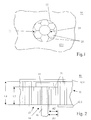
- the panel 10 shown in top view in FIG. 1 is made up of a core layer 11, an upper cover layer 12.1 and a lower cover layer not visible in FIG. 1 Cover layer 12.2 is formed, the two cover layers 12 each mutually opposite surfaces of the core layer 11 with this are connected.
- the core layer 11 has a hole structure, which in the present case a plurality of openings 20 with a honeycomb shape Cross section is formed.
- the honeycomb openings 20 run vertically to the planes of the two cover layers 12 which have their greatest extent.
- openings 20 shown in the exemplary embodiments are all have a honeycomb-shaped cross section is not limited to this Cross-sectional shape connected. This means that in other embodiments the openings 20 can also have round or angular cross sections.
- the core layer 11 is not complete covered with the two deck views 12. Rather, in the two Cover layers 12 left an area 13 uncovered, through which the Core layer 11 is visible. In the middle (the one visible in Figure 1) Openings 20 is a fastening part in the form of a screw 14 plugged in.
- the head 15 of the screw 14 lies on the core layer 11 If necessary, between the core layer 11 and the head 15 Screw 14 also a washer - for example made of foam (not shown).
- Figure 2 can also be seen that the on the with the shaft 16 of the screw 14 provided opening 20 and the side opposite breakthroughs 20 directly adjacent to this opening 20 the remaining openings 20 of the core layer which have a length of L1 11 have a reduced length L2. This reduced length L2 of the Breakthroughs 20 cause them to be opposite the openings 20 a length L1 more easily transverse to the direction of the shaft 16 of the screw 14 deformed.
- FIGS. 3a-c show one of the suspensions according to FIGS. 1 and 2 shown completely different suspension, although both types of suspension a panel 10 can also be used in combination for suspension.
- the panel 10 is with side Distance A surrounded by a bracket 17.
- This bracket 17 is present formed as a U-profile, the free legs 18 of this profile in the direction of the panel 10 show.
- the legs 18 can also have a toothed contour (not shown).
- the corresponding cover layer 12 is formed on a toothed Leg 18 of the circumferential bracket 17 placed and by means of a complementary toothed tool pressed on the leg 18, a Stress built up in the cover layer 12, which, for example, after Obtain setting of the adhesive between leg 18 and cover layer 12 remains.
- other methods known to the person skilled in the art for Build-up of tension in the cover layer 12 connected to the holder 17 be used.
- reference numeral 19 is one Electronics is designated, which with or the drive systems (not for the panel 10 cooperates. This electronics 19 is with the Bracket 17 connected, whereby good heat dissipation from the panel 10 is achieved becomes.
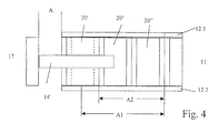
- the embodiment according to FIG. 4 is linked to the embodiment according to Figures 1 and 2.
- the fastening part in the form of a tab 14 'transverse to Direction of extension of the openings 20 connected to the panel 10.
- the openings 20 'to 20 "' are neither with one upper still with a lower cover layer 12.1, 12.2. to the Mobility of the through holes 20 "and 20" '' transversely to their direction of extension to improve. Addition remains in connection with the embodiment according to FIG. 4, only that the distances A1 and A2 shown are not only transverse apply to the direction of view of this figure but perpendicular to it.
- the tab 14 'at a distance A' between the panel and the Bracket 17 can be made elastic.
Abstract
Description
Die Erfindung befaßt sich mit Aufhängungen für Schallwiedergabeanordnungen nach dem Biegewellenprinzip, insbesondere solchen Aufhängungen, welche die beliebige Integration solcher Anordnungen in Einbauöffnungen erlauben, ohne die Biegewellenausbreitung zu behindern.The invention is concerned with mountings for sound reproduction devices according to the principle of flexible shafts, especially those suspensions which allow any integration of such arrangements in installation openings without the To prevent bending wave propagation.
Gemäß dem Stand der Technik sind Schallwiedergabeanordnungen bekannt, die nach dem Biegewellenprinzip arbeiten. Derartige Anordnungen werden im wesentlichen von einem Paneel und wenigstens einem Antriebssystem gebildet, wobei das Paneel in Schwingungen versetzt wird, wenn dem oder den Antriebssystem(en) Tonsignale zugefiihrt werden. Charakteristisch für solche Schallwiedergabeanordnungen ist, daß ab einer kritischen unteren Grenzfrequenz eine "Biegewellenabstrahlung" möglich wird, wobei die Biegewellen entlang der Ebene des jeweiligen Paneels zu einer Schallabstrahlung mit frequenzabhängiger Richtung führen. Mit anderen Worten, ein Schnitt durch ein erstelltes Richtdiagramm zeigt eine Hauptkeule, deren Richtung frequenzabhängig ist. Diese Verhältnisse sind fiir unendlich ausgedehnte Platten und Absorberplatten vollständig gültig, während die Verhältnisse fiir die in dieser Anmeldung behandelten Multiresonanzplatten wegen der starken Randreflexe deutlich komplexer sind. Diese Komplexität bei Multiresonanzplatten rührt daher, daß die genannte Hauptkeule mit frequenzabhängiger Richtung von einer Mehrzahl weiter solcher Hauptkeulen überlagert wird, so daß ein stark aufgefächertes Richtdiagramm entsteht, welches außerdem sehr frequenzabhängig ist. Den hier behandelten. Multresonanzplatten und den Absorberplatten ist aber gemein, daß ihre Richtdiagramme im Mittel eher von der Mittelsenkrechten wegweisen. Dieses Verhalten bewirkt, daß der Raum stärker in die Projektion der Schallwellen einbezogen wird.According to the prior art, sound reproduction arrangements are known which work on the principle of flexible shafts. Such arrangements are in essentially formed by a panel and at least one drive system, wherein the panel is vibrated when the Drive system (s) sound signals are supplied. Characteristic of such Sound reproduction devices is that from a critical lower cut-off frequency a "bending wave radiation" is possible, the bending waves along the Level of the respective panel for sound radiation with frequency-dependent Lead direction. In other words, a cut through a created one Directional diagram shows a main lobe, the direction of which is frequency-dependent. These relationships are for infinitely extended plates and absorber plates fully valid, while the conditions for those in this application treated multi-resonance plates because of the strong edge reflexes clearly are more complex. This complexity in multi-resonance plates stems from the fact that the Main lobe with frequency-dependent direction of a plurality further such main lobes is superimposed, so that a strongly fanned out Directional diagram is created, which is also very frequency-dependent. This one here treated. Mulit-resonance plates and the absorber plates have in common that their average directional diagrams tend to point away from the perpendicular. This behavior causes the space to project more into the Sound waves is included.
Das Paneel ist nach dem Sandwich-Prinzip aufgebaut, indem zwei einander gegenüberliegende Oberflächen einer sehr leichten Kernschicht jeweils mit einer dünnen Deckschicht beispielsweise durch Verklebung verbunden sind. Damit das Paneel gute Schallwiedergabeeigenschaften aufweist, muß das Material für die Deckschicht eine besonders hohe Dehnwellengeschwindigkeit haben. Geeignete Deckschichtmaterialien sind beispielsweise dünne Metallfolien oder auch faserverstärkte Kunststoffolien.The panel is built on the sandwich principle, by two each other opposite surfaces of a very light core layer each with a thin cover layer are connected for example by gluing. So that Panel has good sound reproduction properties, the material for the Top layer have a particularly high expansion shaft speed. Suitable Cover layer materials are, for example, thin metal foils or fiber-reinforced plastic films.
Auch an die Kernschicht werden besondere Anforderungen gestellt. So ist es notwendig, daß die einsetzbaren Materialien zunächst eine geringe Massendichte und eine geringe Dämpfung aufweisen. Außerdem müssen die Materialien für die Kernschicht ein möglichst hohes Schermodul senkrecht zu den Oberflächen haben, die mit den Deckschichten versehen werden. Schließlich ist es im Sinne einer Hauptforderung notwendig, daß die für Kernschichten verwendbaren Materialien in der Richtung, in welcher später die jeweils aus diesem Material gebildete Kernschicht ihre größte Ausdehnung hat, einem sehr geringen Elastizitätsmodul besitzen. Diese in bezug auf die beiden letzten Anforderungen auf den ersten Blick widersprüchlichen Voraussetzungen werden am ehesten von einer Kernschicht erfüllt, die eine Lochstruktur mit zwischen den beiden für die Beschichtung mit den Deckschichten vorgesehenen Oberflächen verlaufenden Durchbrüchen mit vorzugsweise geringem Querschnitt aufweist. Neben den Kernschichten mit der Lochstruktur sind auch Hartschäume als Kernschichtmaterialien einsetzbar, weil diese trotz ihrer isotropen Materialeigenschaften immer noch geeignete Scher- und Elastizitätsmodule aufweisen. Nicht unerwähnt soll in diesem Zusammenhang bleiben, daß bei der Verwendung von Hartschäumen als Material für die Kernschicht die Deckschichten die Aufgabe haben, das geforderte anisotrope Verhalten des Paneels herzustellen.There are also special requirements for the core layer. That's the way it is necessary that the materials that can be used initially have a low mass density and have low damping. In addition, the materials for the Core layer as high a shear modulus perpendicular to the surfaces have, which are provided with the cover layers. After all, it is in the sense A main requirement is that the core layers can be used Materials in the direction in which they are later made from this material formed core layer has its greatest extent, a very small Possess modulus of elasticity. This in relation to the last two requirements At first glance, contradictory prerequisites are most likely to be caused by a core layer that has a hole structure with between the two for the Coating with the surfaces provided for the top layers Breakthroughs with preferably a small cross section. In addition to the Core layers with the perforated structure are also considered rigid foams Core layer materials can be used because they are isotropic Material properties still suitable shear and elasticity modules exhibit. It should not go unmentioned in this context that the Use of rigid foams as the material for the core layer Cover layers have the task of the required anisotropic behavior of the To manufacture panels.
Grundlegende Idee für die Schallwiedergabe nach dem Biegewellenprinzip war es, vorhandene Wände zur Schallstrahlung zu verwenden. Hierbei ging man davon aus, daß es ausreichen müsse, die entsprechenden Wände mit Antriebssystemen zur Erzeugung von Biegewellen auszustatten. Schon bald erkannte man, daß nur für diese Zwecke optimierte Wände in der Lage waren, eine Schallabstrahlung in befriedigender Weise zu garantieren. Voraussetzung dafür war aber, daß derart optimierte Wände in ausreichender Größe zur Verfügung gestellt werden können, damit eine Dämpfung der sich fortsetzenden Wellen an einer starren Einfassung des Paneels unterbleibt. Oftmals ist es aber so, daß aber Flächen, welche ein Paneel der zuvor beschriebenen Größe aufnehmen können, nicht zur Verfügung stehen. Um auch kleine Paneele zu einer akzeptablen Schallwiedergabe einsetzen zu können, ist es notwendig diese mittels elastischer Befestigungsmittel mit einer Halterung zu verbinden. Dazu griff man auf die aus der Lautsprechertechnik bekannten Sicken zurück, welche den Rand des Paneels mit der Halterung verbinden. Abgesehen davon, daß es sich bei den gekannten Sicken um ein zusätzliches Bauteil handelt, sind diese Sicken auch deshalb nachteilig, weil sie den Herstellungsprozeß durch die fiir Anbringung der Sicken notwendigen Prozeßschritte erheblich verteuern. Unabhängig davon ist die reine (Rand-) Befestigung des Paneels auch in den kleineren Abmessungen dann nachteilig, wenn -wie in der Praxis- üblich- das entsprechende Paneel mit einer Mehrzahl von Antriebssystemen ausgestattet ist. Durch diese Maßnahme erhöht sich das Gewicht des ohnehin schon nicht leichten Paneels, so daß zu einer ausreichenden Aufhängung des Paneels die Sicken sehr hart ausgelegt werden müssen, womit gleichzeitig auch die von diesen Sicken ausgehende Dämpfung erhöht wird.The basic idea for sound reproduction according to the bending wave principle was it is to use existing walls for sound radiation. Here you went assume that it should be sufficient to have the appropriate walls with To equip drive systems for the generation of bending shafts. Soon it was recognized that only walls optimized for these purposes were able to to guarantee sound radiation in a satisfactory manner. requirement but it was that such optimized walls in sufficient size Can be made available so that a dampening of the continuing Waves on a rigid border of the panel are avoided. But often it is so that but areas that are a panel of the size described above can record, are not available. To make even small panels into one To be able to use acceptable sound reproduction, it is necessary to use this to connect elastic fasteners with a bracket. One reached for it back to the beads known from loudspeaker technology, which surround the edge of the panel to the bracket. Apart from the fact that the known beads is an additional component, these beads are also disadvantageous because the manufacturing process by attaching the Beading necessary process steps considerably more expensive. Regardless of that pure (edge) fastening of the panel even in the smaller dimensions disadvantageous if - as usual in practice - the corresponding panel with a Most drive systems are equipped. This measure increases the weight of the already not light panel, so that to a sufficient suspension of the panel, the beads can be designed very hard with which the damping emanating from these beads is also given is increased.
Daher liegt der Erfindung die Aufgabe zugrunde, eine Aufhängung fiir Schallwiedergabeanordnungen nach dem Biegewellenprinzip anzugeben, welche die im Stand der Technik bestehenden Nachteile vermeidet.Therefore, the invention has for its object a suspension for Sound reproduction arrangements according to the bending wave principle indicate which avoids the disadvantages existing in the prior art.
Diese Aufgabe wird mit den in Anspruch 1 angegebenen Merkmalen gelöst.
Vorteilhafte Aus- und Weiterbildungen der Erfindung sind den Ansprüchen 2 bis
8 entnehmbar.This object is achieved with the features specified in
Der erfinderische Verdienst der vorliegenden Anmeldung liegt darin, erkannt zu haben, daß die zur Herstellung des Paneels verwendeten Komponenten zur Herstellung einer elastischen Verbindung mit einer Halterung geeignet sind.The inventive step of the present application is to be recognized have that the components used to manufacture the panel for Making an elastic connection with a bracket are suitable.
Hat gemäß Anspruch 2 die Kernschicht eine Lochstruktur, wobei jeder Durchbruch dieser Lochstruktur senkrecht zu den beiden Deckschichten verläuft, und ist zur Realisierung einer Befestigung des Paneels mit der Halterung durch wenigstens einen der Durchbrüche ein Befestigungsteil gesteckt, kann die ohnehin elastische Lochstruktur des Kernmaterials zur elastischen Befestigung genutzt werden, wenn zumindest eine der beiden Deckschichten zu dem oder den mit dem Befestigungsteil versehenen Durchbruch bzw. Durchbrüchen einen seitlichen Abstand A1 einhält, indem eine Mehrzahl der an den oder die mit dem Befestigungsteil versehenen Durchbrüche seitlich unmittelbar angrenzenden Durchbrüche nicht von der bzw. den Deckschichten bedeckt sind. Ob dabei das jeweilige Befestigungsteil parallel oder quer zur Verlaufsrichtung der Durchbrüche verläuft, ist ohne Bedeutung.According to claim 2, the core layer has a hole structure, each Breakthrough of this perforated structure runs perpendicular to the two cover layers, and is to realize a fastening of the panel with the bracket at least one of the openings inserted a fastener, the anyway elastic hole structure of the core material for elastic attachment be used if at least one of the two cover layers to the or with the fastening part provided breakthrough or breakthroughs maintains lateral distance A1 by a plurality of the to or with the Fastening part provided openings immediately adjacent to the side Breakthroughs are not covered by the cover layer or layers. Whether that respective fastening part parallel or transverse to the direction of the Breakthroughs is irrelevant.
Um ein Ausreißen des oder der mit dem Befestigungsteil versehenen Durchbrüche zu verhindern, sollten gemäß Anspruch 3 der oder die Durchbrüche, welche mit den Befestigungsteil versehen sind, und/oder die Durchbrüche, welche seitlichen an den oder die mit dem Befestigungsteil versehenen Durchbrüche angrenzenden, mit einem Kunststoffmaterial ausgeschäumt sein. To tear out the one or those provided with the fastening part To prevent breakthroughs, the breakthrough or breakthroughs which are provided with the fastening part, and / or the openings which lateral to the or the openings provided with the fastening part adjacent, be foamed with a plastic material.
Um die Federwirkung auch bei ausgeschäumten Durchbrüchen zu garantieren, sollte gemäß Anspruch 4 zumindest eine der beiden Deckschichten auch zu den mit Kunststoffmaterial ausgeschäumten Durchbrüchen einen Abstand A2 einhalten.In order to guarantee the spring action even with foamed breakthroughs, According to claim 4, at least one of the two cover layers should also be added to the openings foamed with plastic material a distance A2 adhere.
Eine weiter verbesserte Federwirkung wird dann erzielt, wenn - wie in Anspruch 5 angegeben - der oder die Durchbrüche, welche ein Befestigungsteil aufnehmen, und/oder solche Durchbrüche, welche nicht oder nur mit einer der beiden Deckschichten bedeckt sind, gegenüber den Durchbrüchen in der übrigen Kernschicht eine verminderte Länge haben.A further improved spring action is achieved if - as in claim 5 specified - the or the openings which receive a fastening part, and / or breakthroughs that are not or only with one of the two Cover layers are covered, opposite the breakthroughs in the rest Core layer have a reduced length.
Wegen die Materialbeschaffenheit der Deckschichten können diese gemäß Anspruch 6 gleichzeitig auch als Aufhängungen für das Paneel genutzt werden, indem diese den Abstand A zwischen dem Paneel und einer das Paneel umrandenden Halterung überbrücken. Der weitere Vorteil einer solchen Aufhängung liegt darin, daß durch die Verwendung der Deckschichten ohne großen Aufwand ein ansatzloser Übergang zwischen Halterung und Paneel geschaffen wird.Because of the material properties of the cover layers, these can be according to Claim 6 can also be used as suspensions for the panel, by giving the distance A between the panel and one the panel Bridge the surrounding bracket. The further advantage of such Suspension is that by using the top layers without great effort a seamless transition between bracket and panel is created.
Eine verbesserte Federwirkung der Deckschicht bzw. Deckschichten ist dann gegeben, wenn gemäß Anspruch 7 der Bereich, mit dem die Deckschicht den Abstand A zwischen Paneel und Halterung überbrückt, eine gewellte oder gezackte Kontur aufweist.An improved spring effect of the cover layer or cover layers is then given if, according to claim 7, the area with which the top layer Distance A bridged between panel and bracket, a corrugated or has a jagged contour.
Besonders raumsparend wird die Schallwiedergabeanordnung dann, wenn die Elektronikkomponenten zum Antrieb des Paneel im Abstand A zwischen Halterung und Paneel angeordnet sind. Sind die Elektronikkomponenten mit der Halterung verbunden, erhöhen sie nicht die schwingende Masse. Außerdem wird durch die Befestigung der Elektronikkomponenten an der Halterung für eine verbesserte Wärmeabfuhr von den Elektronikkomponenten gesorgtThe sound reproduction arrangement is particularly space-saving when the Electronic components for driving the panel at a distance A between Bracket and panel are arranged. Are the electronic components with the Bracket connected, they do not increase the vibrating mass. Besides, will by attaching the electronic components to the bracket for one improved heat dissipation from the electronic components
Nur der Vollständigkeit halber sei darauf hingewiesen, daß das jeweilige Paneel auch mittels einer Kombination aus Kernschicht- und Deckschichtaufhängung befestigt sein kann, indem beispielsweise eine der Deckschichten zur Halterung geführt ist und das Paneel entfernt vom Randbereich unter Mitwirkung der Kernschicht abgestützt wird.For the sake of completeness, it should be noted that the respective panel also by means of a combination of core layer and top layer suspension can be attached, for example, by one of the cover layers for mounting is guided and the panel removed from the edge area with the participation of Core layer is supported.
Es zeigen:
Figur 1- ein Paneel in Draufsicht;
- Figur 2
- eine Schnittansicht eines Paneels gemäß
Figur 1, - Figur 3a-c
- drei Schnittansichten ein.es weiteren Paneels; und
- Figur 4
- ein weiteres Paneel in Schnittansicht.
- Figure 1
- a panel in top view;
- Figure 2
- 2 shows a sectional view of a panel according to FIG. 1,
- Figure 3a-c
- three sectional views of another panel; and
- Figure 4
- another panel in sectional view.
Die Erfindung soll nun anhand der Figuren näher erläutert werden.The invention will now be explained in more detail with reference to the figures.
Das in Figur 1 in Draufsicht gezeigte Paneel 10 wird von einer Kernschicht 11,
einer oberen Deckschicht 12.1 und einer in Figur 1 nicht sichtbaren unteren
Deckschicht 12.2 gebildet, wobei die beiden Deckschichten 12 jeweils an
einander gegenüberliegenden Oberflächen der Kernschicht 11 mit dieser
verbunden sind. Die Kernschicht 11 weist eine Lochstruktur auf, welche
vorliegend von einer Mehrzahl von Durchbrüchen 20 mit wabenförmigem
Querschnitt gebildet ist. Die wabenförmigen Durchbrüche 20 verlaufen senkrecht
zu den ihre größte Ausdehnung habenden Ebenen der beiden Deckschichten 12.The
Auch wenn die in den Ausführungsbeispielen gezeigten Durchbrüche 20 alle
einen wabenförmigen Querschnitt haben, ist damit keine Beschränkung auf diese
Querschnittsform verbunden. Dies bedeutet, daß in anderen Ausführungsformen
die Durchbrüche 20 auch runde oder eckige Querschnitte haben können.Even if the
Wie der Figur 1 deutlich entnehmbar ist, ist die Kernschicht 11 nicht vollständig
mit den beiden Decksichten 12 bedeckt. Vielmehr wird in den beiden
Deckschichten 12 ein Bereich 13 unbedeckt gelassen., durch welchen die
Kernschicht 11 sichtbar wird. In den mittleren (der in Figur 1 sichtbaren)
Durchbrüche 20 ist ein Befestigungsteil in der Form einer Schraube 14
eingesteckt. Dabei liegt der Kopf 15 der Schraube 14 auf der Kernschicht 11 auf
Sofern erforderlich kann zwischen der Kernschicht 11 und dem Kopf 15 der
Schraube 14 auch noch eine Unterlegscheibe -beispielsweise aus Schaumstoff(nicht
dargestellt) angeordnet sein. Auch ist Figur 2 entnehmbar, daß die an dem
mit dem Schaft 16 der Schraube 14 versehenen Durchbruch 20 sowie die seitlich
unmittelbar an diesen Durchbruch 20 angrenzenden Durchbniche 20 gegenüber
den übrigen und eine Länge von L1 habenden Durchbrüchen 20 der Kernschicht
11 eine verminderte von Länge L2 haben. Diese verminderte Länge L2 der
Durchbniche 20 bewirkt, daß sich diese gegenüber der Durchbrüchen 20 mit
einer Länge L1 leichter quer zur Richtung des Schafts 16 der Schraube 14
verformen lassen.As can be clearly seen in FIG. 1, the
Ferner ist der Figur 2 durch die angedeutete Punktierung entnehmbar, daß der
Durchbruch 20, durch welchen der Schaft 16 der Schraube 14 verläuft, mit einem
Kunststoffmaterial ausgeschäumt ist. Hierdurch wird verhindertet, daß dieser
Durchbruch 20 beschädigt wird, wenn der Schaft 16 der Schraube 14 mit einer
Halterung (nicht dargestellt) verbunden ist und das Paneel 10 wellenförmig
verformt wird.It can also be seen from FIG. 2 by the indicated dotting that the
Nur der Vollständigkeit halber sie darauf hingewiesen, daß in Figur 2 die obere
Deckschicht 12.1 oberhalb der Durchbrüche 20 mit der venninderten Länge L2
keinen freien, die Kernschicht 11 nicht abdeckenden Bereich 13 aufweist,
sondern auch diese Durchbrüche 20 vollständig überdeckt. Hierdurch wird an der
oberen Deckschicht 12.1 eine durchgehende Oberfläche geschaffen, was sie
Optik eines solchen Paneel 10 verbessert.For the sake of completeness, they pointed out that the upper one in FIG
Cover layer 12.1 above the
Außerdem ist der Schnittdarstellung gemäß Figur entnehmbar, daß zur
Verbesserung der Federwirkung der Kernschicht der Bereich 13 in der unteren
Deckschicht 12.2 sowohl zu der Schraube 14 einen Abstand A1 als auch zu der
Ausschäumung einen Abstand A2 einhält. Wesentlich dabei ist daß der Abstand
A1 größer ist als der Abstand A2, denn nur bei Einhaltung dieser Bedingungen
wird eine freie Federwirkung unter Ausnutzung der Kemschicht 11 gewährleistet.In addition, the sectional view according to the figure can be seen that for
Improvement of the spring action of the core layer of the
In den Figuren 3a-c ist eine von der Aufhängung gemäß den Figuren 1 und 2
völlig verschiedene Aufhängung dargestellt, obwohl beide Aufhängungsarten
auch kombiniert zur Aufhängung eine Paneels 10 verwendet werden können.FIGS. 3a-c show one of the suspensions according to FIGS. 1 and 2
shown completely different suspension, although both types of suspension
a
Bei der Anordnung gemäß den Figuren 3a-c wird das Paneel 10 mit seitlichem
Abstand A von einer Halterung 17 umrandet. Diese Halterung 17 ist vorliegend
als U-Profil ausgebildet, wobei die freien Schenkel 18 dieses Profils in Richtung
des Paneels 10 zeigen.In the arrangement according to Figures 3a-c, the
Bei der Ausführungsform gemäß Figur 3a überspannen die beiden mit der
Kernschicht 11 verbunden Deckschichten 12.1, 12.2 den Abstand A flach und
sind mit den Schenkeln 18 des Profils verbunden. Um in sehr einfacher Weise
eine gewisse Spannung in den Deckschichten 12 zu erzielen, wenn sie mit den
Schenkeln 18 der das Paneel 10 unrandenden Halterung 17 verbunden sind,
können die Schenkel 18 auch eine gezahnte Kontur aufweisen (nicht gezeigt).
Wird dann die entsprechende Deckschicht 12 auf einen gezahnt ausgebildeten
Schenkel 18 der umlaufenden Halterung 17 aufgelegt und mittels eines
komplementär gezahnten Werkzeugs auf den Schenkel 18 gedrückt, wird eine
Spannung in der Deckschicht 12 aufgebaut, welche beispielsweise nach
Abbinden des Klebstoffs zwischen Schenkel 18 und Deckschicht 12 erhalten
bleibt. Es können aber auch andere dem Fachmann bekannte Methoden zum
Aufbau einer Spannung in der mit der Halterung 17 verbundenen Deckschicht 12
eingesetzt werden.In the embodiment according to FIG. 3a, the two span with the
Den Figuren 3b und c ist entnehmbar, daß die beiden Deckschichten 12 nicht in
der Ebene der Paneels zur Halterung 17 geführt sein müssen, sondern in dem
Bereich, in dem sie den Abstand A überspannen auch gewölbt (Figur 3b) oder
auch gezackt (Figur 3c) ausgebildet sein können. Auch ist die Wölbung oder
Zackung der Deckschichten 12 im Bereich des Abstandes A nicht auf eine
Wölbung oder Zackung beschränkt. Ferner ist festzuhalten, daß die Form, die
Dicke und die Materialeigenschaften der Deckschichten 12.1, 12.2 über die
Federeigenschaften entscheiden. Schließlich sei noch nachgetragen, daß nicht
notwendig beide Deckschichten 12..1, 12.2 eines Paneels 10 mit der Halterung 17
verbunden sein. müssen.It can be seen from FIGS. 3b and c that the two cover layers 12 are not in
the level of the panels must be guided to the
Bei der Ausführungsform gemäß Figur 3a ist mit dem Bezugszeichen 19 eine
Elektronik bezeichnet ist, welche mit dem oder den Antriebssystemen (nicht
dargestellt) fiir das Paneel 10 zusammenwirkt. Diese Elektronik 19 ist mit der
Halterung 17 verbunden, wodurch eine gute Wärmeabfuhr vom Paneel 10 erreicht
wird.In the embodiment according to FIG. 3a,
Das Ausführungsbeispiel gemäß Figur 4 knüpft an die Ausführungsform gemäß
den Figuren 1 und 2 an. Im Gegensatz zu den letztbenannten Ausführungsformen
ist das Befestigungsteil in der Form einer Lasche 14' quer zur
Erstreckungsrichtung der Durchbrüche 20 mit dem Paneel 10 verbunden. Um für
eine ausreichende Befestigung der Lasche 14' im Paneel 10 zu sorgen, ist -wie
durch die Punktierung angedeutet- der Durchbruch 20', welcher vollständig von
der Lasche 14' durchdrungen ist, vollständig mit Kunststoffmaterial
ausgeschäumt. Außerdem sind die Durchbrüche 20' bis 20"' weder mit einer
oberen noch mit einer unteren Deckschicht 12.1, 12.2 versehen., um die
Beweglichkeit der Durchbniche 20" und 20''' quer zu ihrer Erstreckungsrichtung
zu verbessern. Nachzutragen bleibt im Zusammenhang mit der Ausführungsform
gemäß Figur 4 nur noch, daß die gezeigten Abstände A1 und A2 nicht nur quer
zur Blickrichtung auf diese Figur sondern senkrecht dazu gelten.The embodiment according to FIG. 4 is linked to the embodiment according to
Figures 1 and 2. In contrast to the latter embodiments
is the fastening part in the form of a tab 14 'transverse to
Direction of extension of the
Sofern die über die Durchbrüche 20'',20''' herstellte Federwirkung nicht
ausreichen sollte, kann diese in einem anderen -nicht dargestellten-Ausführungsbeispiel
die Lasche 14' im Abstand A' zwischen dem Paneel und der
Halterung 17 elastisch ausgebildet werden kann.Unless the spring action produced via the
Claims (8)
mit einer Halterung 17, und
mit elastischen Befestigungsmitteln, welche das Paneel 10 mit der Halterung 17 verbinden,
dadurch gekennzeichnet;
daß die elastischen Befestigungsmittel von der Kernschicht 11 und/oder wenigstens einer der beiden Deckschichten 12 gebildet werden.Suspension for sound reproduction arrangements according to the bending wave principle with a panel 10, which is formed by a core layer 11 and two cover layers 12.1, 12.2, the two cover layers 12 being connected to two opposite surfaces of the core layer 11,
with a bracket 17, and
with elastic fastening means which connect the panel 10 to the holder 17,
characterized;
that the elastic fastening means are formed by the core layer 11 and / or at least one of the two cover layers 12.
dadurch gekennzeichnet,
characterized,
dadurch gekennzeichnet,
daß der oder die Durchbrüche 20, welche mit den Befestigungsteil 14 versehen sind, und/oder die Durchbrüche 20, welche seitlichen an den oder die mit dem Befestigungsteil 14 versehenen Durchbrüche 20 angrenzenden, mit einem Kunststoffmaterial ausgeschäumt sind.Suspension according to claim 2
characterized,
that the one or more openings 20, which are provided with the fastening part 14, and / or the openings 20, which are adjacent to the one or more openings provided with the fastening part 14, are foamed with a plastic material.
dadurch gekennzeichnet,
daß zumindest eine der beiden Deckschichten 12 auch zu den mit Kunststoffmaterial aus geschäumten Durchbrüchen 20 einen Abstand A2 einhalten. Suspension according to claim 3
characterized,
that at least one of the two cover layers 12 also maintain a distance A2 from the openings 20 which are foamed with plastic material.
dadurch gekennzeichnet,
daß der oder die Durchbrüche 20, welche ein Befestigungsteil 14 aufnehmen, und/oder solche Durchbrüche 20, welche nicht oder nur mit einer der beiden Deckschichten 12 bedeckt sind, gegenüber der Länge L1 der Durchbrüche 20 in der übrigen Kemschicht 11 eine verminderte Länge L2 haben.Suspension according to one of claims 2-4
characterized,
that the or the openings 20, which receive a fastening part 14, and / or such openings 20, which are not or only covered with one of the two cover layers 12, have a reduced length L2 compared to the length L1 of the openings 20 in the remaining core layer 11 .
dadurch gekennzeichnet,
daß die Halterung 17 das Paneel 10 mit seitlichem Abstand A umrandet und daß zumindest eine der beiden Deckschichten 12 unter Überbrückung des seitlichen Abstandes A mit der Halterung 17 verbunden ist.Suspension according to claim 1
characterized,
that the holder 17 surrounds the panel 10 with a lateral distance A and that at least one of the two cover layers 12 is connected to the holder 17 by bridging the lateral distance A.
dadurch gekennzeichnet,
daß die Bereiche der Deckschichten 12, welche den seitlichen Abstand A zur Halterung 17 überbrücken eine gewellte oder gezackte Kontur aufweisen.Suspension according to claim 6
characterized,
that the areas of the cover layers 12 which bridge the lateral distance A to the holder 17 have a corrugated or serrated contour.
dadurch gekennzeichnet,
daß im seitlichen Abstand A zwischen dem Paneel 10 und der Halterung 17 Elektonikkomponenten zum 19 Antrieb des Paneel 10 angeordnet und mit der Halterung 17 verbunden sind.Suspension according to claim 6 or claim 7
characterized,
that 17 are arranged in the lateral distance A between the panel 10 and the bracket 17 electronic components for 19 driving the panel 10 and connected to the bracket 17.
Applications Claiming Priority (2)
| Application Number | Priority Date | Filing Date | Title |
|---|---|---|---|
| DE19757098A DE19757098C2 (en) | 1997-12-20 | 1997-12-20 | Suspension for sound reproduction arrangements based on the bending wave principle |
| DE19757098 | 1997-12-20 |
Publications (3)
| Publication Number | Publication Date |
|---|---|
| EP0924960A2 true EP0924960A2 (en) | 1999-06-23 |
| EP0924960A3 EP0924960A3 (en) | 2005-04-13 |
| EP0924960B1 EP0924960B1 (en) | 2009-11-25 |
Family
ID=7852892
Family Applications (1)
| Application Number | Title | Priority Date | Filing Date |
|---|---|---|---|
| EP98123818A Expired - Lifetime EP0924960B1 (en) | 1997-12-20 | 1998-12-15 | Suspension for sound reproduction arrangements based on the bending wave principle |
Country Status (4)
| Country | Link |
|---|---|
| US (1) | US6160898A (en) |
| EP (1) | EP0924960B1 (en) |
| JP (1) | JPH11252684A (en) |
| DE (2) | DE19757098C2 (en) |
Cited By (9)
| Publication number | Priority date | Publication date | Assignee | Title |
|---|---|---|---|---|
| WO1999052324A1 (en) * | 1998-04-02 | 1999-10-14 | New Transducers Limited | Acoustic device relying on bending wave action |
| WO1999060818A1 (en) * | 1998-05-15 | 1999-11-25 | Harman Audio Electronic Systems Gmbh | Panel loudspeaker |
| EP1100287A1 (en) * | 1999-11-10 | 2001-05-16 | M- Tech(HK) Co. Ltd | Loudspeaker |
| WO2001047320A1 (en) * | 1999-12-21 | 2001-06-28 | New Transducers Limited | Loudspeakers |
| WO2002013575A1 (en) * | 2000-08-03 | 2002-02-14 | New Transducers Limited | Bending wave loudspeaker |
| US6546106B2 (en) | 1996-09-03 | 2003-04-08 | New Transducers Limited | Acoustic device |
| US6826285B2 (en) | 2000-08-03 | 2004-11-30 | New Transducers Limited | Bending wave loudspeaker |
| US6836552B1 (en) | 1998-06-10 | 2004-12-28 | Harman Audio Electronic Systems Gmbh | Panel loudspeakers |
| EP1604750A1 (en) * | 2004-06-08 | 2005-12-14 | ACHENBACH BUSCHHÜTTEN GmbH | Device for measuring tensile stress distribution in metal strip |
Families Citing this family (30)
| Publication number | Priority date | Publication date | Assignee | Title |
|---|---|---|---|---|
| DE19757099A1 (en) * | 1997-12-20 | 1999-06-24 | Nokia Deutschland Gmbh | Contacting for a sound reproduction arrangement based on the bending wave principle |
| DE19821862A1 (en) | 1998-05-15 | 1999-11-18 | Nokia Deutschland Gmbh | Flat panel loudspeaker |
| DE19821860A1 (en) | 1998-05-15 | 1999-11-18 | Nokia Deutschland Gmbh | Driver for flat panel loudspeaker |
| DE19843079A1 (en) * | 1998-09-19 | 2000-03-23 | Nokia Deutschland Gmbh | Multi-resonance plate |
| US6044925A (en) * | 1998-11-30 | 2000-04-04 | Sahyoun; Joseph Yaacoub | Passive speaker |
| US20040188175A1 (en) * | 1998-11-30 | 2004-09-30 | Sahyoun Joseph Yaacoub | Audio speaker with wobble free voice coil movement |
| US7185735B2 (en) * | 1998-11-30 | 2007-03-06 | Joseph Yaacoub Sahyoun | Audio speaker with wobble free voice coil movement |
| US6675931B2 (en) | 1998-11-30 | 2004-01-13 | Joseph Yaacoub Sahyoun | Low profile audio speaker |
| US7225895B2 (en) * | 1998-11-30 | 2007-06-05 | Joseph Yaacoub Sahyoun | Audio speaker with wobble free voice coil movement |
| DE19943084A1 (en) * | 1999-09-09 | 2001-04-05 | Harman Audio Electronic Sys | Sound transducer |
| DE10001410C2 (en) * | 2000-01-14 | 2001-12-06 | Harman Audio Electronic Sys | Flat speaker arrangement |
| US6751329B2 (en) * | 2000-09-21 | 2004-06-15 | New Transducers Limited | Loudspeaker driver |
| US7180489B2 (en) * | 2002-02-06 | 2007-02-20 | Andersen Corporation | Automated multi-task window assembly |
| US7109959B2 (en) | 2002-02-06 | 2006-09-19 | Andersen Corporation | Multi-task window |
| AU2003272919A1 (en) * | 2002-10-25 | 2004-05-13 | Matsushita Electric Industrial Co., Ltd. | Suspension and electro-acoustic transducer using the suspension |
| JP4031977B2 (en) * | 2002-11-26 | 2008-01-09 | 有限会社ファル | Planar speaker and speaker system using the same |
| US8116512B2 (en) * | 2006-09-14 | 2012-02-14 | Bohlender Graebener Corporation | Planar speaker driver |
| US8204269B2 (en) * | 2008-08-08 | 2012-06-19 | Sahyoun Joseph Y | Low profile audio speaker with minimization of voice coil wobble, protection and cooling |
| US8540049B2 (en) | 2010-12-23 | 2013-09-24 | Bose Corporation | Acoustic diaphragm suspending |
| WO2012155726A1 (en) * | 2011-05-19 | 2012-11-22 | Huang Xinmin | Vibrating plate device of electromagnetic vibrator and manufacture method thereof |
| CN202949560U (en) * | 2012-11-16 | 2013-05-22 | 瑞声声学科技(常州)有限公司 | Sounder |
| US9788122B2 (en) * | 2012-12-26 | 2017-10-10 | Xin Min HUANG | Vibrating panel device for electromagnetic vibrator and manufacture method thereof |
| DE102014012327B3 (en) * | 2014-08-20 | 2015-12-03 | Helge Bots | Soundboard for improving the sound characteristics of conventional loudspeakers |
| US9654879B2 (en) | 2014-10-24 | 2017-05-16 | Bose Corporation | Suspension for acoustic device |
| US9466280B2 (en) | 2014-10-24 | 2016-10-11 | Bose Corporation | Acoustic device suspension |
| US10701490B2 (en) | 2015-09-14 | 2020-06-30 | Wing Acoustics Limited | Audio transducers |
| US9924273B2 (en) | 2016-03-31 | 2018-03-20 | Bose Corporation | Acoustic device configuration and method |
| US11166100B2 (en) | 2017-03-15 | 2021-11-02 | Wing Acoustics Limited | Bass optimization for audio systems and devices |
| TW201904310A (en) | 2017-03-22 | 2019-01-16 | 紐西蘭商威恩音響有限公司 | System, method and device for audio converter, thin electronic device and hinge system |
| CN111818427A (en) * | 2019-04-10 | 2020-10-23 | 鸿富锦精密工业(深圳)有限公司 | Vibration system, speaker and method for manufacturing vibration system |
Citations (3)
| Publication number | Priority date | Publication date | Assignee | Title |
|---|---|---|---|---|
| GB1003608A (en) * | 1962-01-15 | 1965-09-08 | Akg Akustische Kino Geraete | Improvements in or relating to diaphragms for loudspeakers |
| JPS56112197A (en) * | 1980-02-12 | 1981-09-04 | Pioneer Electronic Corp | Flat diaphragm for speaker |
| JPS5767398A (en) * | 1980-10-15 | 1982-04-23 | Sony Corp | Dynamic speaker |
Family Cites Families (16)
| Publication number | Priority date | Publication date | Assignee | Title |
|---|---|---|---|---|
| US2063945A (en) * | 1933-08-02 | 1936-12-15 | Pierce George Washington | Diaphragm and method |
| US2744042A (en) * | 1951-06-21 | 1956-05-01 | Goodyear Tire & Rubber | Laminated panels |
| DE1132593B (en) * | 1965-04-05 | 1962-07-05 | Bolt Beranek & Newman | Acoustically effective plate, especially for coupling to an electroacoustic transducer |
| DE2112516B1 (en) * | 1971-03-16 | 1972-10-19 | Kurtze Guenther Dipl Phys Prof | Directional loudspeaker |
| JPS5379525A (en) * | 1976-12-23 | 1978-07-14 | Sony Corp | Compound diaphtagm for speakers |
| JPS5748153Y2 (en) * | 1977-11-26 | 1982-10-22 | ||
| JPS603277B2 (en) * | 1978-06-15 | 1985-01-26 | ソニー株式会社 | speaker device |
| JPS5568795A (en) * | 1978-11-20 | 1980-05-23 | Sony Corp | Speaker |
| US4322584A (en) * | 1979-06-30 | 1982-03-30 | Pioneer Electronic Corporation | Voice coil bobbin for planar diaphragm |
| US4410768A (en) * | 1980-07-23 | 1983-10-18 | Nippon Gakki Seizo Kabushiki Kaisha | Electro-acoustic transducer |
| US4471173A (en) * | 1982-03-01 | 1984-09-11 | Magnepan, Inc. | Piston-diaphragm speaker |
| JPS619098A (en) * | 1984-06-25 | 1986-01-16 | Hitachi Ltd | Speaker |
| US4969197A (en) * | 1988-06-10 | 1990-11-06 | Murata Manufacturing | Piezoelectric speaker |
| DE4343324A1 (en) * | 1993-12-18 | 1995-06-22 | Nokia Deutschland Gmbh | Suspension for cone speakers |
| JPH11512246A (en) * | 1995-09-02 | 1999-10-19 | ニュー トランスデューサーズ リミテッド | Loudspeaker with panel-type acoustic radiating element |
| US6044925A (en) * | 1998-11-30 | 2000-04-04 | Sahyoun; Joseph Yaacoub | Passive speaker |
-
1997
- 1997-12-20 DE DE19757098A patent/DE19757098C2/en not_active Expired - Fee Related
-
1998
- 1998-12-15 EP EP98123818A patent/EP0924960B1/en not_active Expired - Lifetime
- 1998-12-15 DE DE59814416T patent/DE59814416D1/en not_active Expired - Lifetime
- 1998-12-18 US US09/216,155 patent/US6160898A/en not_active Expired - Lifetime
- 1998-12-21 JP JP10363300A patent/JPH11252684A/en active Pending
Patent Citations (3)
| Publication number | Priority date | Publication date | Assignee | Title |
|---|---|---|---|---|
| GB1003608A (en) * | 1962-01-15 | 1965-09-08 | Akg Akustische Kino Geraete | Improvements in or relating to diaphragms for loudspeakers |
| JPS56112197A (en) * | 1980-02-12 | 1981-09-04 | Pioneer Electronic Corp | Flat diaphragm for speaker |
| JPS5767398A (en) * | 1980-10-15 | 1982-04-23 | Sony Corp | Dynamic speaker |
Non-Patent Citations (2)
| Title |
|---|
| PATENT ABSTRACTS OF JAPAN Bd. 0051, Nr. 86 (E-084), 25. November 1981 (1981-11-25) & JP 56 112197 A (PIONEER ELECTRONIC CORP), 4. September 1981 (1981-09-04) * |
| PATENT ABSTRACTS OF JAPAN Bd. 0061, Nr. 44 (E-122), 3. August 1982 (1982-08-03) & JP 57 067398 A (SONY CORP), 23. April 1982 (1982-04-23) * |
Cited By (13)
| Publication number | Priority date | Publication date | Assignee | Title |
|---|---|---|---|---|
| US6546106B2 (en) | 1996-09-03 | 2003-04-08 | New Transducers Limited | Acoustic device |
| GB2350008A (en) * | 1998-04-02 | 2000-11-15 | New Transducers Ltd | Acoustic device relying on bending wave action |
| GB2350008B (en) * | 1998-04-02 | 2001-05-02 | New Transducers Ltd | Acoustic device |
| WO1999052324A1 (en) * | 1998-04-02 | 1999-10-14 | New Transducers Limited | Acoustic device relying on bending wave action |
| WO1999060818A1 (en) * | 1998-05-15 | 1999-11-25 | Harman Audio Electronic Systems Gmbh | Panel loudspeaker |
| US7236601B1 (en) | 1998-05-15 | 2007-06-26 | Wolfgang Bachmann | Panel loudspeaker |
| US6836552B1 (en) | 1998-06-10 | 2004-12-28 | Harman Audio Electronic Systems Gmbh | Panel loudspeakers |
| EP1100287A1 (en) * | 1999-11-10 | 2001-05-16 | M- Tech(HK) Co. Ltd | Loudspeaker |
| WO2001047320A1 (en) * | 1999-12-21 | 2001-06-28 | New Transducers Limited | Loudspeakers |
| GB2371941A (en) * | 1999-12-21 | 2002-08-07 | New Transducers Ltd | Loudspeakers |
| WO2002013575A1 (en) * | 2000-08-03 | 2002-02-14 | New Transducers Limited | Bending wave loudspeaker |
| US6826285B2 (en) | 2000-08-03 | 2004-11-30 | New Transducers Limited | Bending wave loudspeaker |
| EP1604750A1 (en) * | 2004-06-08 | 2005-12-14 | ACHENBACH BUSCHHÜTTEN GmbH | Device for measuring tensile stress distribution in metal strip |
Also Published As
| Publication number | Publication date |
|---|---|
| US6160898A (en) | 2000-12-12 |
| EP0924960A3 (en) | 2005-04-13 |
| EP0924960B1 (en) | 2009-11-25 |
| DE59814416D1 (en) | 2010-01-07 |
| DE19757098A1 (en) | 1999-06-24 |
| DE19757098C2 (en) | 2003-01-09 |
| JPH11252684A (en) | 1999-09-17 |
Similar Documents
| Publication | Publication Date | Title |
|---|---|---|
| DE19757098C2 (en) | Suspension for sound reproduction arrangements based on the bending wave principle | |
| DE60105521T2 (en) | Sound absorbing the element particularly for aircraft engines | |
| EP2406069B1 (en) | Multilayer board for sound insulation | |
| EP1886301B1 (en) | Sandwich structure having a frequency-selective double-wall behavior | |
| EP0924959B1 (en) | Sound reproduction arrangement | |
| EP1078552B1 (en) | Device for dynamic excitation of panel loudspeakers | |
| DE102004053383A1 (en) | Acoustic absorber for aircraft engines | |
| DE202007005265U1 (en) | Mounting plate for door closer, has receiving side opposite to mounting side for receiving door closer, where closer is fastened with mounting side at receiving body such as door frame, where plate is made steel material | |
| DE1250202B (en) | Device for damping the bending vibrations of a surface | |
| EP1004538B1 (en) | High-rigidity elevator car floor | |
| EP1078551B1 (en) | Panel loudspeaker | |
| EP1086606B1 (en) | Panel loudspeakers | |
| DE19757099A1 (en) | Contacting for a sound reproduction arrangement based on the bending wave principle | |
| DE3315566C2 (en) | Bearing element, in particular for mounting the engine of a motor vehicle | |
| DE3913347A1 (en) | Sound-insulating layer for flat surface - comprises regular hollow spaces enclosed by paper-strip walls | |
| WO2020126651A1 (en) | Sound insulation element for the firewall of a vehicle body and support element for a sound insulation element of this type | |
| EP3593987B1 (en) | Acoustic component | |
| DE3144124C2 (en) | Sound-insulating component, in particular a door leaf | |
| DE202005002592U1 (en) | Insulating plate of hard plastic foam is provided at least on one side with a pattern of recesses with bottom and side surfaces oriented respectively parallel and perpendicular to the plate side | |
| DE60302974T2 (en) | Method of making arrangements of sandwich structures | |
| DE906710C (en) | Housing with built-in chassis for radio sets | |
| WO2023227732A1 (en) | Sound absorption device with vibroacoustic metamaterials and noise barrier comprising at least one such soundproofing device | |
| DE2604452C3 (en) | Quartz crystal resonator with a beveled crystal body | |
| DE10239013A1 (en) | Shock-filtering device | |
| DE2604452B2 (en) | QUARTZ CRYSTAL RESONATOR WITH A BEVELED AREA CRYSTAL BODY |
Legal Events
| Date | Code | Title | Description |
|---|---|---|---|
| PUAI | Public reference made under article 153(3) epc to a published international application that has entered the european phase |
Free format text: ORIGINAL CODE: 0009012 |
|
| AK | Designated contracting states |
Kind code of ref document: A2 Designated state(s): AT BE CH CY DE DK ES FI FR GB GR IE IT LI LU MC NL PT SE |
|
| AX | Request for extension of the european patent |
Free format text: AL;LT;LV;MK;RO;SI |
|
| RAP1 | Party data changed (applicant data changed or rights of an application transferred) |
Owner name: HARMAN AUDIO ELECTRONIC SYSTEMS GMBH |
|
| RIC1 | Information provided on ipc code assigned before grant |
Ipc: 7H 04R 7/04 B Ipc: 7H 04R 7/20 A |
|
| PUAL | Search report despatched |
Free format text: ORIGINAL CODE: 0009013 |
|
| AK | Designated contracting states |
Kind code of ref document: A3 Designated state(s): AT BE CH CY DE DK ES FI FR GB GR IE IT LI LU MC NL PT SE |
|
| AX | Request for extension of the european patent |
Extension state: AL LT LV MK RO SI |
|
| 17P | Request for examination filed |
Effective date: 20050608 |
|
| AKX | Designation fees paid |
Designated state(s): BE DE ES FR GB IT NL |
|
| RAP1 | Party data changed (applicant data changed or rights of an application transferred) |
Owner name: HARMAN BECKER AUTOMOTIVE SYSTEMS GMBH |
|
| GRAP | Despatch of communication of intention to grant a patent |
Free format text: ORIGINAL CODE: EPIDOSNIGR1 |
|
| RBV | Designated contracting states (corrected) |
Designated state(s): BE DE ES FR GB IT NL |
|
| GRAS | Grant fee paid |
Free format text: ORIGINAL CODE: EPIDOSNIGR3 |
|
| GRAA | (expected) grant |
Free format text: ORIGINAL CODE: 0009210 |
|
| AK | Designated contracting states |
Kind code of ref document: B1 Designated state(s): BE DE ES FR GB IT NL |
|
| REG | Reference to a national code |
Ref country code: GB Ref legal event code: FG4D Free format text: NOT ENGLISH |
|
| REF | Corresponds to: |
Ref document number: 59814416 Country of ref document: DE Date of ref document: 20100107 Kind code of ref document: P |
|
| REG | Reference to a national code |
Ref country code: NL Ref legal event code: VDEP Effective date: 20091125 |
|
| BERE | Be: lapsed |
Owner name: HARMAN BECKER AUTOMOTIVE SYSTEMS G.M.B.H. Effective date: 20091231 |
|
| PG25 | Lapsed in a contracting state [announced via postgrant information from national office to epo] |
Ref country code: NL Free format text: LAPSE BECAUSE OF FAILURE TO SUBMIT A TRANSLATION OF THE DESCRIPTION OR TO PAY THE FEE WITHIN THE PRESCRIBED TIME-LIMIT Effective date: 20091125 Ref country code: ES Free format text: LAPSE BECAUSE OF FAILURE TO SUBMIT A TRANSLATION OF THE DESCRIPTION OR TO PAY THE FEE WITHIN THE PRESCRIBED TIME-LIMIT Effective date: 20100308 |
|
| PLBE | No opposition filed within time limit |
Free format text: ORIGINAL CODE: 0009261 |
|
| STAA | Information on the status of an ep patent application or granted ep patent |
Free format text: STATUS: NO OPPOSITION FILED WITHIN TIME LIMIT |
|
| PG25 | Lapsed in a contracting state [announced via postgrant information from national office to epo] |
Ref country code: BE Free format text: LAPSE BECAUSE OF NON-PAYMENT OF DUE FEES Effective date: 20091231 |
|
| 26N | No opposition filed |
Effective date: 20100826 |
|
| PG25 | Lapsed in a contracting state [announced via postgrant information from national office to epo] |
Ref country code: IT Free format text: LAPSE BECAUSE OF FAILURE TO SUBMIT A TRANSLATION OF THE DESCRIPTION OR TO PAY THE FEE WITHIN THE PRESCRIBED TIME-LIMIT Effective date: 20091125 |
|
| PGFP | Annual fee paid to national office [announced via postgrant information from national office to epo] |
Ref country code: GB Payment date: 20141229 Year of fee payment: 17 |
|
| PGFP | Annual fee paid to national office [announced via postgrant information from national office to epo] |
Ref country code: FR Payment date: 20141217 Year of fee payment: 17 |
|
| PGFP | Annual fee paid to national office [announced via postgrant information from national office to epo] |
Ref country code: DE Payment date: 20141230 Year of fee payment: 17 |
|
| REG | Reference to a national code |
Ref country code: DE Ref legal event code: R119 Ref document number: 59814416 Country of ref document: DE |
|
| GBPC | Gb: european patent ceased through non-payment of renewal fee |
Effective date: 20151215 |
|
| REG | Reference to a national code |
Ref country code: FR Ref legal event code: ST Effective date: 20160831 |
|
| PG25 | Lapsed in a contracting state [announced via postgrant information from national office to epo] |
Ref country code: DE Free format text: LAPSE BECAUSE OF NON-PAYMENT OF DUE FEES Effective date: 20160701 Ref country code: GB Free format text: LAPSE BECAUSE OF NON-PAYMENT OF DUE FEES Effective date: 20151215 |
|
| PG25 | Lapsed in a contracting state [announced via postgrant information from national office to epo] |
Ref country code: FR Free format text: LAPSE BECAUSE OF NON-PAYMENT OF DUE FEES Effective date: 20151231 |