EP0924692B1 - Control of the surface roughness of magnetic disks - Google Patents
Control of the surface roughness of magnetic disks Download PDFInfo
- Publication number
- EP0924692B1 EP0924692B1 EP98120658A EP98120658A EP0924692B1 EP 0924692 B1 EP0924692 B1 EP 0924692B1 EP 98120658 A EP98120658 A EP 98120658A EP 98120658 A EP98120658 A EP 98120658A EP 0924692 B1 EP0924692 B1 EP 0924692B1
- Authority
- EP
- European Patent Office
- Prior art keywords
- disk
- magnetic
- substrate
- accordance
- head
- Prior art date
- Legal status (The legal status is an assumption and is not a legal conclusion. Google has not performed a legal analysis and makes no representation as to the accuracy of the status listed.)
- Expired - Lifetime
Links
- 230000003746 surface roughness Effects 0.000 title description 4
- 238000000034 method Methods 0.000 claims description 38
- 230000008569 process Effects 0.000 claims description 28
- QVGXLLKOCUKJST-UHFFFAOYSA-N atomic oxygen Chemical compound [O] QVGXLLKOCUKJST-UHFFFAOYSA-N 0.000 claims description 23
- 229910052760 oxygen Inorganic materials 0.000 claims description 23
- 239000001301 oxygen Substances 0.000 claims description 23
- 229910052751 metal Inorganic materials 0.000 claims description 18
- 239000002184 metal Substances 0.000 claims description 18
- 238000004544 sputter deposition Methods 0.000 claims description 17
- 239000011651 chromium Substances 0.000 claims description 10
- 230000003647 oxidation Effects 0.000 claims description 8
- 238000007254 oxidation reaction Methods 0.000 claims description 8
- 229910052804 chromium Inorganic materials 0.000 claims description 7
- VYZAMTAEIAYCRO-UHFFFAOYSA-N Chromium Chemical compound [Cr] VYZAMTAEIAYCRO-UHFFFAOYSA-N 0.000 claims description 6
- 230000002950 deficient Effects 0.000 claims 1
- 239000007789 gas Substances 0.000 claims 1
- 239000007788 liquid Substances 0.000 claims 1
- 239000000758 substrate Substances 0.000 description 32
- XLYOFNOQVPJJNP-UHFFFAOYSA-N water Substances O XLYOFNOQVPJJNP-UHFFFAOYSA-N 0.000 description 18
- 239000010410 layer Substances 0.000 description 9
- 238000004519 manufacturing process Methods 0.000 description 8
- 239000010408 film Substances 0.000 description 5
- 238000005406 washing Methods 0.000 description 5
- IJGRMHOSHXDMSA-UHFFFAOYSA-N Atomic nitrogen Chemical compound N#N IJGRMHOSHXDMSA-UHFFFAOYSA-N 0.000 description 4
- 238000000576 coating method Methods 0.000 description 4
- 230000009467 reduction Effects 0.000 description 4
- 235000019592 roughness Nutrition 0.000 description 4
- 239000010409 thin film Substances 0.000 description 4
- OKTJSMMVPCPJKN-UHFFFAOYSA-N Carbon Chemical compound [C] OKTJSMMVPCPJKN-UHFFFAOYSA-N 0.000 description 3
- 230000009471 action Effects 0.000 description 3
- 230000015572 biosynthetic process Effects 0.000 description 3
- 229910052799 carbon Inorganic materials 0.000 description 3
- 239000011248 coating agent Substances 0.000 description 3
- 238000007872 degassing Methods 0.000 description 3
- 230000000694 effects Effects 0.000 description 3
- 238000004626 scanning electron microscopy Methods 0.000 description 3
- 235000019587 texture Nutrition 0.000 description 3
- NBIIXXVUZAFLBC-UHFFFAOYSA-N Phosphoric acid Chemical compound OP(O)(O)=O NBIIXXVUZAFLBC-UHFFFAOYSA-N 0.000 description 2
- VYPSYNLAJGMNEJ-UHFFFAOYSA-N Silicium dioxide Chemical compound O=[Si]=O VYPSYNLAJGMNEJ-UHFFFAOYSA-N 0.000 description 2
- XUIMIQQOPSSXEZ-UHFFFAOYSA-N Silicon Chemical compound [Si] XUIMIQQOPSSXEZ-UHFFFAOYSA-N 0.000 description 2
- 238000005299 abrasion Methods 0.000 description 2
- 238000004140 cleaning Methods 0.000 description 2
- 238000011109 contamination Methods 0.000 description 2
- 238000005260 corrosion Methods 0.000 description 2
- 230000007797 corrosion Effects 0.000 description 2
- QDOXWKRWXJOMAK-UHFFFAOYSA-N dichromium trioxide Chemical compound O=[Cr]O[Cr]=O QDOXWKRWXJOMAK-UHFFFAOYSA-N 0.000 description 2
- 238000009826 distribution Methods 0.000 description 2
- 230000002349 favourable effect Effects 0.000 description 2
- 238000004518 low pressure chemical vapour deposition Methods 0.000 description 2
- 239000000314 lubricant Substances 0.000 description 2
- 230000007246 mechanism Effects 0.000 description 2
- 239000002609 medium Substances 0.000 description 2
- 239000000203 mixture Substances 0.000 description 2
- 229910052757 nitrogen Inorganic materials 0.000 description 2
- 239000011241 protective layer Substances 0.000 description 2
- 229910052710 silicon Inorganic materials 0.000 description 2
- 239000010703 silicon Substances 0.000 description 2
- 238000003860 storage Methods 0.000 description 2
- 239000000725 suspension Substances 0.000 description 2
- 229910000861 Mg alloy Inorganic materials 0.000 description 1
- 229910005855 NiOx Inorganic materials 0.000 description 1
- CBENFWSGALASAD-UHFFFAOYSA-N Ozone Chemical compound [O-][O+]=O CBENFWSGALASAD-UHFFFAOYSA-N 0.000 description 1
- BLRPTPMANUNPDV-UHFFFAOYSA-N Silane Chemical compound [SiH4] BLRPTPMANUNPDV-UHFFFAOYSA-N 0.000 description 1
- 238000003070 Statistical process control Methods 0.000 description 1
- GANNOFFDYMSBSZ-UHFFFAOYSA-N [AlH3].[Mg] Chemical compound [AlH3].[Mg] GANNOFFDYMSBSZ-UHFFFAOYSA-N 0.000 description 1
- 230000002776 aggregation Effects 0.000 description 1
- 238000004220 aggregation Methods 0.000 description 1
- 239000004411 aluminium Substances 0.000 description 1
- 229910052782 aluminium Inorganic materials 0.000 description 1
- XAGFODPZIPBFFR-UHFFFAOYSA-N aluminium Chemical compound [Al] XAGFODPZIPBFFR-UHFFFAOYSA-N 0.000 description 1
- 229910000147 aluminium phosphate Inorganic materials 0.000 description 1
- 239000012736 aqueous medium Substances 0.000 description 1
- 230000008901 benefit Effects 0.000 description 1
- 230000001680 brushing effect Effects 0.000 description 1
- 238000012512 characterization method Methods 0.000 description 1
- 238000006243 chemical reaction Methods 0.000 description 1
- 229910052681 coesite Inorganic materials 0.000 description 1
- 229910052906 cristobalite Inorganic materials 0.000 description 1
- 238000013500 data storage Methods 0.000 description 1
- 238000005137 deposition process Methods 0.000 description 1
- 229910003460 diamond Inorganic materials 0.000 description 1
- 239000010432 diamond Substances 0.000 description 1
- 238000001035 drying Methods 0.000 description 1
- 238000005530 etching Methods 0.000 description 1
- 238000001704 evaporation Methods 0.000 description 1
- 230000008020 evaporation Effects 0.000 description 1
- 230000004907 flux Effects 0.000 description 1
- 230000004927 fusion Effects 0.000 description 1
- 238000001198 high resolution scanning electron microscopy Methods 0.000 description 1
- 238000000265 homogenisation Methods 0.000 description 1
- 238000007602 hot air drying Methods 0.000 description 1
- 238000007654 immersion Methods 0.000 description 1
- 230000006872 improvement Effects 0.000 description 1
- 230000005764 inhibitory process Effects 0.000 description 1
- 230000003993 interaction Effects 0.000 description 1
- 239000000463 material Substances 0.000 description 1
- 150000002739 metals Chemical class 0.000 description 1
- 239000002086 nanomaterial Substances 0.000 description 1
- 229910052759 nickel Inorganic materials 0.000 description 1
- OFNHPGDEEMZPFG-UHFFFAOYSA-N phosphanylidynenickel Chemical compound [P].[Ni] OFNHPGDEEMZPFG-UHFFFAOYSA-N 0.000 description 1
- 229910052697 platinum Inorganic materials 0.000 description 1
- 230000002028 premature Effects 0.000 description 1
- 230000001681 protective effect Effects 0.000 description 1
- 239000000377 silicon dioxide Substances 0.000 description 1
- 238000004659 sterilization and disinfection Methods 0.000 description 1
- 229910052682 stishovite Inorganic materials 0.000 description 1
- 239000000126 substance Substances 0.000 description 1
- 238000012876 topography Methods 0.000 description 1
- 229910052905 tridymite Inorganic materials 0.000 description 1
- 238000010792 warming Methods 0.000 description 1
Images
Classifications
-
- G—PHYSICS
- G11—INFORMATION STORAGE
- G11B—INFORMATION STORAGE BASED ON RELATIVE MOVEMENT BETWEEN RECORD CARRIER AND TRANSDUCER
- G11B5/00—Recording by magnetisation or demagnetisation of a record carrier; Reproducing by magnetic means; Record carriers therefor
- G11B5/84—Processes or apparatus specially adapted for manufacturing record carriers
- G11B5/8404—Processes or apparatus specially adapted for manufacturing record carriers manufacturing base layers
Definitions
- the present invention relates to the manufacture of magnetic disks.
- it relates to a process for the control of the micro-roughness of the surfaces of magnetic disks.
- Magnetic disks are data storage devices with a very large storage capacity. Ca. 400 million characters (bytes) can be stored on a magnetic disk of about 95 mm.
- the disks must also exhibit exact mechanical and also certain tribological properties. In subsequent practical use, the disks move at ca. 5400 revolutions per minute. This means that the outer edge of the disk reaches a velocity of up to 100 km/h, while the read/write head is less than one ten thousandth of a millimetre ( ⁇ 100 nm) from the surface of the disk.
- a magnetic thin-film medium is employed for recording the data in modern high-capacity magnetic disks.
- a magnetic head rests on the surface of the magnetic disk within a circumferential, data-free start-stop zone when the magnetic disk drive is not in use.
- the magnetic disk is usually provided with a lubricant.
- a lubricant if the surface of the disk is essentially smooth, the high surface energy of the lubricant leads to greatly increased adhesion between the head and disk (stiction). As a consequence, the force required to turn the disk and lift the head is increased. This can easily lead to deformation and damage to the extremely delicate magnetic head suspension and hence to a failure of the whole drive.
- the surface of the magnetic disk is usually roughened-prior to the application of the magnetically active thin film, that is, given a texture so that the head, when it slides over the surface on which it is set down on the disk, comes into contact with very slight roughnesses (asperities) instead of with the smooth disk surface.
- a texturing process either a number of very small grooves or valleys are ground in the magnetic disk (mechanical texturing) or deliberate elevations are produced by local fusion (laser texturing). Examples of such texturing processes can be found in US Patents 4,287,225; 4,698,251; 4,735,840 and 4,973,496.
- IBM TDB Vol. 34, No. 5, pp. 381-382 describes the use of plasma processes for the manufacture of random nanostructures on a surface.
- EP-A-0 567 748 discloses the manufacture and use of rough silicon surfaces.
- the manufacture of such surfaces with a control of the roughness density comprises a) an LPCVD (Low Pressure Chemical Vapour Deposition) process in the region of 1-5 mTorr and b) the use of a surface of thermal SiO 2 , which undergoes relatively little reaction with SiH 4 at a temperature in the region of 500-600°C.
- a silicon surface treated in such a way is used, i.a., as a substrate for a magnetic disk of low stiction.
- chromium (Cr) is evaporated onto an aluminium-magnesium alloy substrate which supports a nickel-phosphorus surface film.
- US-A-5456978 discloses a magnetic thin film mechanism which is produced by sputtering a chromium sublayer with a sputtered chromium underlayer.
- the sublayer may be partially oxidised.
- the substrate predominantly used is NiP coated aluminium, to which metal atoms are applied by sputtering.
- sputter metals used are Cr, Ni and Co+Cr+Pt, Co+Cr+Pt+Ta, etc., where chromium is particularly preferred.
- the metal atoms grow faster on those regions of the surface of the magnetic disk which energetically favour the growth. This applies to regions which have a thicker oxide layer than their surroundings (oxide islands). Preferential oxidation takes place on regions of special topography (elevations, grooves, scratches, etc. at the atomic level) or in regions with a particular surface composition, which is thermodynamically favourable to metal growth.
- nodules small metal atom aggregations, the so-called nodules. These nodules are dressed by the layers (magnetic layer, protective layer) subsequently applied and lead to approximately hemi-spherical protrusions on the finished disk surface.
- the size and density of the nodules have a marked influence on the properties of the magnetic disk. If the nodules are relatively small and numerous (diameter 10-20 nm), the surface obtained is microscopically relatively smooth and homogeneous, allowing a very low float height for the magnetic head and hence an efficient magnetic interaction between head and disk. However, if the head comes to rest on a disk with very small nodules, the high adhesion forces can result in an increase in stiction.
- a further negative aspect of large nodules is the danger of surface damage in the post-sputtering cleaning processes, which act abrasively on asperities and lead to damage to the topmost protective layer of the disk. This greatly reduces the corrosion resistance of the disk to the action of moisture and harmful substances.
- the present invention permits control of the size of the nodules. and thus deliberately influence the micro-roughness of the magnetic disk.
- method for the surface texturising of magnetic disks comprising a step of sputtering metal atoms onto the surface of the magnetic disk, wherein certain areas of the surface of the magnetic disk are selectively oxidised before the sputtering process; characterise in that the selective oxidation is carried out in a rinsing process carried out prior to the sputtering.
- the process in accordance with the invention enables the surface roughness of the magnetic disk caused by the nodules to be deliberately controlled when desired. This has the advantage of targeted reduction of stiction, increase in magnetic performance and improvement of the corrosion-resistance of the magnetic disk.
- NiP-coated Al substrate is textured mechanically for example, with a diamond suspension (production of scoring), vigorously washed (pre-sputter wash) and then vacuum coated in a sputter process with a metal film and a protective film of diamond-like carbon (carbon overcoat). After further cleaning the disk is then lubricated and finally tested magnetically and mechanically.
- the NiP substrate surface is etched using an aggressive cleaner (for example, a flux or phosphoric acid-containing solution), as a result of which texturing residues and the entire surface oxide film are removed.
- an aggressive cleaner for example, a flux or phosphoric acid-containing solution
- the last pre-wash step comprises immersion of the cleaned substrate in hot water, thus warming the substrate sufficiently so, that it dries, in a very short time.
- the substrate surface is oxidised as a result of the oxygen dissolved in the rinse water, forming superficial oxides (NiO x , NiPO x ). Since this oxidation does not take place uniformly but preferably at places which exhibit corresponding topographical features, such as grooves, scratches, etc., or which have a particular surface composition, where there are thermodynamically favourable conditions, the result is to form so-called oxide islands, which have a higher oxide content than their surroundings. The oxide islands subsequently react preferentially with the elementary, highly reactive sputtered metal. Thermodynamically very stable oxides, for example, Cr 2 O 3 when chromium is used as the sputter metal, are thus obtained which form nucleating points for further metal growth.
- the invention now envisages precise control of the oxygen content of the aqueous medium in the final rinse process before the sputtering process itself, thus controlling the oxidation taking place on the surface of the substrate.
- selective oxidation of preferred regions of the surface is obtained, namely those on which grooves, scratches, etc., appear or corresponding thermodynamic requirements are met (oxide islands).
- the rinsing material must be at a high temperature, which is in the range from about 30 to 80°C, preferably 60°C.
- Untreated water i.e. no disinfection through ozone treatment, etc.
- a reduction of the dissolved oxygen content of the rinse water to values in the region of 0-4 mg O 2 /l, for example, by degassing (introducing nitrogen) leads to a significant slowing down of the oxidation of the surface of the substrate during contact with the rinse water.
- the formation of regions with a heavier oxide coating is then incomplete and the result is either no oxide islands or only very small and not very pronounced islands.
- a thin and very homogeneous oxide coating is formed on the substrate surface as a result of the action of atmospheric oxygen.
- substrates and finished processed magnetic disks which had been treated with different amounts of oxygen in the final rinsing step of the substrate washing process were compared with one another.
- the reduction of the oxygen content in the rinse water was effected by gassing with nitrogen in a conventional degassing unit.
- the "normal”, i.e. un-degassed rinse water, served as a reference.
- the temperature of the rinse water was 60°C in both cases.
- the substrate was first textured and then washed.
- the complete washing process consisted of an etching process and a sequence of brushing and rinsing steps.
- the topographical surface characterisation was carried out using high-resolution scanning electron microscopy (SEM) at a magnification of x 50000.
- Fig. 1 shows the surface of a substrate rinsed with water at 60°C having an oxygen content of ca. 8 mg O 2 /l and Fig. 2 the surface of a substrate rinsed with water having an oxygen content of ca. 1.7 mg O 2 /l.
- a "normal” oxygen content is to be understood in this example to be a value of ca. 8 mg O 2 /l.
- "Low oxygen” water in this example means a value of ca. 2 mg O 2 /l.
- the surface rinsed with the higher oxygen content shows smaller protuberances (nodules) with a diameter of a maximum of 10 nm, while on the surface rinsed with degassed water these protuberances are completely lacking or are no longer detectable with the SEM.
- the present substrates were then provided with a Cr layer (30 nm thick), a Co/Pt/Cr layer (40 nm thick) and a carbon layer (10 nm thick) in subsequent sputtering processes and lubricated.
- Fig. 3 shows the surface of a magnetic disk produced from a normal substrate, i.e. one processed with oxygen-containing rinse water.
- Hemi-spherical protuberances with a diameter of 50-60 nm are clearly recognisable. The density of these nodules is broadly comparable with the density of the corresponding substrate protuberances.
- Fig. 4 shows the surface of a magnetic disk made from a substrate treated with degassed rinse water. It exhibits no protuberances detectable with the SEM and thus correlates with the corresponding completely smooth substrate surface.
- the difference between the two disk surfaces is significant and well reproducible.
- the substrate treated with degassed warm water provides, apart from the texture roughness, completely smooth surfaces, while the substrates rinsed with warm water having a higher oxygen content exhibit immediately after the washing process small protuberances (oxide islands) on the surface, from which relatively large nodules are produced during the subsequent sputtering process.
- the surface roughness of the magnetic disks can be precisely adjusted by controlling the oxygen content of the rinse water before the sputtering process.
Landscapes
- Engineering & Computer Science (AREA)
- Manufacturing & Machinery (AREA)
- Magnetic Record Carriers (AREA)
- Manufacturing Of Magnetic Record Carriers (AREA)
Description
- The present invention relates to the manufacture of magnetic disks. In particular, it relates to a process for the control of the micro-roughness of the surfaces of magnetic disks.
- Magnetic disks are data storage devices with a very large storage capacity. Ca. 400 million characters (bytes) can be stored on a magnetic disk of about 95 mm.
- Besides the high storage density, the disks must also exhibit exact mechanical and also certain tribological properties. In subsequent practical use, the disks move at ca. 5400 revolutions per minute. This means that the outer edge of the disk reaches a velocity of up to 100 km/h, while the read/write head is less than one ten thousandth of a millimetre (< 100 nm) from the surface of the disk.
- Only by observing the greatest precision during manufacture and by statistical process control is it possible to attain these quality requirements.
- Because of its high density, a magnetic thin-film medium is employed for recording the data in modern high-capacity magnetic disks. In one generally widespread arrangement, a magnetic head rests on the surface of the magnetic disk within a circumferential, data-free start-stop zone when the magnetic disk drive is not in use.
- An alternative arrangement is the so-called load/unload mechanism, in which the thin film head rests outside the disk and is only guided over the disk surface when it engages in read/write activity.
- As a result of the turning motion of the disk a cushion of air which supports the head is formed in both processes between the head and the disk.
- The conditions prevailing at the boundary layer between magnetic head and disk throw up a number of tribological problems. In the arrangement described, in which the head rests within the start/stop zone, the magnetic head slides over the surface of the disk until the speed of rotation of the disk is high enough to lift the head. Surface contamination, which can arise from contact of the head with the disk, can lead to abrasion of the corrosion-resistant coatings on the disk and lead to premature failure of the disk or the head.
- To reduce abrasion and wear, the magnetic disk is usually provided with a lubricant. However, if the surface of the disk is essentially smooth, the high surface energy of the lubricant leads to greatly increased adhesion between the head and disk (stiction). As a consequence, the force required to turn the disk and lift the head is increased. This can easily lead to deformation and damage to the extremely delicate magnetic head suspension and hence to a failure of the whole drive.
- To reduce this undesirable adhesion effect, the surface of the magnetic disk is usually roughened-prior to the application of the magnetically active thin film, that is, given a texture so that the head, when it slides over the surface on which it is set down on the disk, comes into contact with very slight roughnesses (asperities) instead of with the smooth disk surface. In such a texturing process, either a number of very small grooves or valleys are ground in the magnetic disk (mechanical texturing) or deliberate elevations are produced by local fusion (laser texturing). Examples of such texturing processes can be found in US Patents 4,287,225; 4,698,251; 4,735,840 and 4,973,496.
- Even with the so-called load/unload arrangement, in which the magnetic head is parked outside the disk, the texture or surface roughness of the magnetic disk plays a great part in respect of a lowest possible magnetically effective gap between magnetic head and disk.
- IBM TDB Vol. 34, No. 5, pp. 381-382 describes the use of plasma processes for the manufacture of random nanostructures on a surface.
- EP-A-0 567 748 discloses the manufacture and use of rough silicon surfaces. The manufacture of such surfaces with a control of the roughness density comprises a) an LPCVD (Low Pressure Chemical Vapour Deposition) process in the region of 1-5 mTorr and b) the use of a surface of thermal SiO2, which undergoes relatively little reaction with SiH4 at a temperature in the region of 500-600°C. A silicon surface treated in such a way is used, i.a., as a substrate for a magnetic disk of low stiction.
- Research Disclosure n289, May 1988 disclosed the evaporation of a so-called "metal undercoat" onto a substrate to achieve texturing. The evaporated metal film produces a uniform micro-roughness, so that the magnetic layer and coating subsequently applied reproduce this roughness. In a particular embodiment, chromium (Cr) is evaporated onto an aluminium-magnesium alloy substrate which supports a nickel-phosphorus surface film.
- US-A-5456978 discloses a magnetic thin film mechanism which is produced by sputtering a chromium sublayer with a sputtered chromium underlayer. The sublayer may be partially oxidised. Thus this document corresponds to the pre-characterising part of claim 1.
- The aforementioned processes have, however, the disadvantage that they do not permit precise control of the micro-roughness of the surface and/or are very time-consuming and therefore cost-intensive.
- Although the present invention can also be employed for the so-called load/unload arrangement, only the use in those applications where the magnetic head rests in a start/stop zone on the disk is discussed below.
- In the manufacture of magnetic disks for desktop and server drives, the substrate predominantly used is NiP coated aluminium, to which metal atoms are applied by sputtering. Examples of sputter metals used are Cr, Ni and Co+Cr+Pt, Co+Cr+Pt+Ta, etc., where chromium is particularly preferred. During the sputtering process, the metal atoms grow faster on those regions of the surface of the magnetic disk which energetically favour the growth. This applies to regions which have a thicker oxide layer than their surroundings (oxide islands). Preferential oxidation takes place on regions of special topography (elevations, grooves, scratches, etc. at the atomic level) or in regions with a particular surface composition, which is thermodynamically favourable to metal growth. At these places at which the preferential growth takes place, small metal atom aggregations, the so-called nodules, are produced. These nodules are dressed by the layers (magnetic layer, protective layer) subsequently applied and lead to approximately hemi-spherical protrusions on the finished disk surface.
- The size and density of the nodules have a marked influence on the properties of the magnetic disk. If the nodules are relatively small and numerous (diameter 10-20 nm), the surface obtained is microscopically relatively smooth and homogeneous, allowing a very low float height for the magnetic head and hence an efficient magnetic interaction between head and disk. However, if the head comes to rest on a disk with very small nodules, the high adhesion forces can result in an increase in stiction.
- Large nodules (ca. 50-60 mm (sic)) with a low density of distribution, on the other hand, increase the magnetically active gap between head and disk and thus reduce the attainable write density. In addition, they produce asperities which increase the tribologically caused wear of the disk, coupled with scaling on the magnetic head, and so shorten the service life of the disk drive.
- On the other hand, if the head/disk interface used tends to increased stiction, for example, through organic contamination or very smooth head surface, then large nodules, by reducing the effective contact surface of the head with the disk, act to reduce the head/disk adhesion forces.
- A further negative aspect of large nodules is the danger of surface damage in the post-sputtering cleaning processes, which act abrasively on asperities and lead to damage to the topmost protective layer of the disk. This greatly reduces the corrosion resistance of the disk to the action of moisture and harmful substances.
- There is therefore great interest in being able to control the size of the nodules as precisely as possible, i.e. in bringing them into a region which, on the one hand, reduces the danger of stiction and, on the other hand, minimises the magnetically active distance in respect of the maximum possible write/read performance.
- The present invention permits control of the size of the nodules. and thus deliberately influence the micro-roughness of the magnetic disk.
According to the present invention there is provided method for the surface texturising of magnetic disks, comprising a step of sputtering metal atoms onto the surface of the magnetic disk, wherein certain areas of the surface of the magnetic disk are selectively oxidised before the sputtering process; characterise in that the selective oxidation is carried out in a rinsing process carried out prior to the sputtering.
Further advantageous embodiments of the method in accordance with the invention are set out in the subclaims. - The process in accordance with the invention enables the surface roughness of the magnetic disk caused by the nodules to be deliberately controlled when desired. This has the advantage of targeted reduction of stiction, increase in magnetic performance and improvement of the corrosion-resistance of the magnetic disk.
- The method in accordance with the invention is further described with reference to the drawings.
- These show:
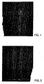
- Fig. 1
- the surface of a substrate with normal oxygen content rinsed at 60°C;
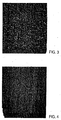
- Fig. 2
- the surface of a substrate rinsed with low oxygen water;
- Fig. 3
- the surface of a magnetic disk prepared from a substrate shown in Fig. 1; and
- Fig. 4
- the surface of a magnetic disk made from a substrate shown in Fig. 2.
- In the manufacture of desktop and server magnetic disks an NiP-coated Al substrate is textured mechanically for example, with a diamond suspension (production of scoring), vigorously washed (pre-sputter wash) and then vacuum coated in a sputter process with a metal film and a protective film of diamond-like carbon (carbon overcoat). After further cleaning the disk is then lubricated and finally tested magnetically and mechanically.
- In a washing step preceding the sputter process proper the NiP substrate surface is etched using an aggressive cleaner (for example, a flux or phosphoric acid-containing solution), as a result of which texturing residues and the entire surface oxide film are removed. This is followed by more brush and rinse steps. The last pre-wash step comprises immersion of the cleaned substrate in hot water, thus warming the substrate sufficiently so, that it dries, in a very short time.
- The substrate surface is oxidised as a result of the oxygen dissolved in the rinse water, forming superficial oxides (NiOx, NiPOx). Since this oxidation does not take place uniformly but preferably at places which exhibit corresponding topographical features, such as grooves, scratches, etc., or which have a particular surface composition, where there are thermodynamically favourable conditions, the result is to form so-called oxide islands, which have a higher oxide content than their surroundings. The oxide islands subsequently react preferentially with the elementary, highly reactive sputtered metal. Thermodynamically very stable oxides, for example, Cr2O3 when chromium is used as the sputter metal, are thus obtained which form nucleating points for further metal growth.
- The invention now envisages precise control of the oxygen content of the aqueous medium in the final rinse process before the sputtering process itself, thus controlling the oxidation taking place on the surface of the substrate. In this way, selective oxidation of preferred regions of the surface is obtained, namely those on which grooves, scratches, etc., appear or corresponding thermodynamic requirements are met (oxide islands). For this, the rinsing material must be at a high temperature, which is in the range from about 30 to 80°C, preferably 60°C.
- Untreated water (i.e. no disinfection through ozone treatment, etc.) has an oxygen content at 60°C of about 4-5 mg/l. A reduction of the dissolved oxygen content of the rinse water to values in the region of 0-4 mg O2/l, for example, by degassing (introducing nitrogen) leads to a significant slowing down of the oxidation of the surface of the substrate during contact with the rinse water. The formation of regions with a heavier oxide coating is then incomplete and the result is either no oxide islands or only very small and not very pronounced islands. On finally drying the substrate in a standard atmosphere a thin and very homogeneous oxide coating is formed on the substrate surface as a result of the action of atmospheric oxygen.
- For the metal, atoms arriving at the surface of the substrate during the subsequent sputtering process no region with an increased thickness of oxide is visible and many small metal growth points are formed which then lead to the formation of small nodules (diameter ca. 10 nm) with very high surface density.
- In addition, it is possible to effect homogenisation, i.e. a reduction in the nodule size distribution, if the substrate is subjected to hot air drying after the rinsing process. As a result of the action of the hot air a particularly uniform growth of the surface oxide layer is achieved, leading again to the inhibition of a preferred metal growth in the subsequent sputtering process so that numerous small nodules of similar size are formed.
- Increasing the oxygen content in the rinse medium to values in the region of about 5-10 mg O2/l, for example by switching off the degassing and/or optionally introducing additional oxygen, on the other hand, causes the formation of clearly visible oxide islands on the substrate surface. These islands have an approximate diameter of ≤ 10 nm and a height of ca. 5-10 nm. In the subsequent deposition process very large nodules (50-60 nm diameter) with a low density through preferential growth of the metal atoms on the oxide islands can be generated.
- In order to demonstrate the effectiveness of the present invention, substrates and finished processed magnetic disks which had been treated with different amounts of oxygen in the final rinsing step of the substrate washing process were compared with one another. The reduction of the oxygen content in the rinse water was effected by gassing with nitrogen in a conventional degassing unit. The "normal", i.e. un-degassed rinse water, served as a reference. The temperature of the rinse water was 60°C in both cases.
- The substrate was first textured and then washed. The complete washing process consisted of an etching process and a sequence of brushing and rinsing steps.
- The topographical surface characterisation was carried out using high-resolution scanning electron microscopy (SEM) at a magnification of x 50000.
- Fig. 1 shows the surface of a substrate rinsed with water at 60°C having an oxygen content of ca. 8 mg O2/l and Fig. 2 the surface of a substrate rinsed with water having an oxygen content of ca. 1.7 mg O2/l.
- A "normal" oxygen content is to be understood in this example to be a value of ca. 8 mg O2/l. "Low oxygen" water in this example means a value of ca. 2 mg O2/l.
- It can be clearly seen that the surface rinsed with the higher oxygen content shows smaller protuberances (nodules) with a diameter of a maximum of 10 nm, while on the surface rinsed with degassed water these protuberances are completely lacking or are no longer detectable with the SEM.
- The present substrates were then provided with a Cr layer (30 nm thick), a Co/Pt/Cr layer (40 nm thick) and a carbon layer (10 nm thick) in subsequent sputtering processes and lubricated.
- Fig. 3 shows the surface of a magnetic disk produced from a normal substrate, i.e. one processed with oxygen-containing rinse water. Hemi-spherical protuberances (nodules) with a diameter of 50-60 nm are clearly recognisable. The density of these nodules is broadly comparable with the density of the corresponding substrate protuberances.
- Fig. 4 shows the surface of a magnetic disk made from a substrate treated with degassed rinse water. It exhibits no protuberances detectable with the SEM and thus correlates with the corresponding completely smooth substrate surface.
- The difference between the two disk surfaces is significant and well reproducible. The substrate treated with degassed warm water provides, apart from the texture roughness, completely smooth surfaces, while the substrates rinsed with warm water having a higher oxygen content exhibit immediately after the washing process small protuberances (oxide islands) on the surface, from which relatively large nodules are produced during the subsequent sputtering process.
- In this way, the surface roughness of the magnetic disks can be precisely adjusted by controlling the oxygen content of the rinse water before the sputtering process.
Claims (7)
- Method for the surface texturising of magnetic disks, comprising a step of sputtering metal atoms onto the surface of the magnetic disk, wherein certain areas of the surface of the magnetic disk are selectively oxidised before the sputtering process; characterised in that the selective oxidation is carried out in a rinsing process carried out prior to the sputtering.
- Method in accordance with claim 1 wherein the selective oxidation is achieved by controlling the oxygen content in the rinsing process.
- Method in accordance with claim 2 wherein the control of the oxygen content is effected by gassing with a non-reactive gas.
- Method in accordance with claim 4, wherein the control of the oxygen content is effected by controlling the introduction of oxygen.
- Method in accordance with any one of the foregoing claims, wherein chromium is employed as the metal in the sputtering process.
- Method in accordance with any one of the foregoing claims, wherein the temperature of the liquid used in the rinsing process is in the range 30 - 80°C and preferably at 60°C.
- Method in accordance with one of the foregoing claims, characterised in that the certain areas of the surface are defective areas such as scratches, irregularities, etc.
Applications Claiming Priority (2)
| Application Number | Priority Date | Filing Date | Title |
|---|---|---|---|
| DE19756410A DE19756410A1 (en) | 1997-12-18 | 1997-12-18 | Control of the surface roughness of magnetic disks |
| DE19756410 | 1997-12-18 |
Publications (2)
| Publication Number | Publication Date |
|---|---|
| EP0924692A1 EP0924692A1 (en) | 1999-06-23 |
| EP0924692B1 true EP0924692B1 (en) | 2006-01-25 |
Family
ID=7852448
Family Applications (1)
| Application Number | Title | Priority Date | Filing Date |
|---|---|---|---|
| EP98120658A Expired - Lifetime EP0924692B1 (en) | 1997-12-18 | 1998-11-04 | Control of the surface roughness of magnetic disks |
Country Status (3)
| Country | Link |
|---|---|
| US (1) | US6203672B1 (en) |
| EP (1) | EP0924692B1 (en) |
| DE (2) | DE19756410A1 (en) |
Family Cites Families (9)
| Publication number | Priority date | Publication date | Assignee | Title |
|---|---|---|---|---|
| DE2909891A1 (en) | 1979-03-14 | 1980-09-25 | Basf Ag | MAGNETIC RECORDING CARRIER |
| US4698251A (en) | 1985-01-22 | 1987-10-06 | Victor Company Of Japan, Limited | Magnetic recording medium and method of producing the same |
| US4735840A (en) | 1985-11-12 | 1988-04-05 | Cyberdisk, Inc. | Magnetic recording disk and sputtering process and apparatus for producing same |
| US4816119A (en) * | 1987-09-04 | 1989-03-28 | Digital Equipment Corp. | Process for production of magnetic media |
| US4973496A (en) | 1989-11-02 | 1990-11-27 | International Business Machines Corporation | Method for texturing magnetic disks |
| JPH0620958A (en) * | 1992-04-10 | 1994-01-28 | Internatl Business Mach Corp <Ibm> | Formation of rough silicon surface and its application |
| US5635037A (en) * | 1993-08-02 | 1997-06-03 | Industrial Technology Research Institute | Method of texture by in-situ masking and etching for thin film magnetic recording medium |
| US5456978A (en) * | 1993-08-03 | 1995-10-10 | Hmt Technology Corporation | Thin-film recording medium with thin metal sublayer |
| US5441788A (en) * | 1993-11-03 | 1995-08-15 | Hewlett-Packard Company | Method of preparing recording media for a disk drive and disk drive recording media |
-
1997
- 1997-12-18 DE DE19756410A patent/DE19756410A1/en not_active Ceased
-
1998
- 1998-11-04 DE DE69833294T patent/DE69833294T2/en not_active Expired - Fee Related
- 1998-11-04 EP EP98120658A patent/EP0924692B1/en not_active Expired - Lifetime
- 1998-12-18 US US09/215,101 patent/US6203672B1/en not_active Expired - Fee Related
Also Published As
| Publication number | Publication date |
|---|---|
| DE19756410A1 (en) | 1999-06-24 |
| US6203672B1 (en) | 2001-03-20 |
| EP0924692A1 (en) | 1999-06-23 |
| DE69833294T2 (en) | 2006-11-16 |
| DE69833294D1 (en) | 2006-04-13 |
Similar Documents
| Publication | Publication Date | Title |
|---|---|---|
| US5635037A (en) | Method of texture by in-situ masking and etching for thin film magnetic recording medium | |
| JPH1074318A (en) | Production of support for magnetic disk | |
| US5506017A (en) | Method for texturing magnetic media | |
| EP0534624B1 (en) | Magnetic recording disk | |
| JPH08102033A (en) | Thin-film magnetic recording disk and manufacture thereof | |
| US6986956B2 (en) | Method of coating smooth electroless nickel on magnetic memory disks and related memory devices | |
| US5427867A (en) | Substrate used for magnetic disk and magnetic recording medium using the substrate | |
| US6203672B1 (en) | Control of the surface roughness of magnetic disk | |
| JPH0520658A (en) | Substrate for magnetic recording medium and production thereof | |
| US6132813A (en) | High density plasma surface modification for improving antiwetting properties | |
| JPH02285508A (en) | Magnetic recording medium | |
| EP0399747B1 (en) | Substrate used for magnetic disk and magnetic recording medium using the substrate | |
| US5928750A (en) | Sputtered thermally cycled texture layers formed of high melting point materials | |
| US4681669A (en) | Method for producing magnetic recording media | |
| JPH05342532A (en) | Method of manufacturing thin film magnetic disk | |
| JPH04255908A (en) | Substrate for magnetic disk | |
| JPH10512386A (en) | Sputtered, thermally cycled tissue layer made of high melting point material | |
| JPH04295614A (en) | magnetic recording medium | |
| EP0555906A1 (en) | Glass substrate for magnetic recording medium | |
| JPH05128505A (en) | Manufacture of thin-film magnetic disk | |
| JPH11232638A (en) | Magnetic disk and method of manufacturing the same | |
| JPH0546975A (en) | Method for texturing titanium magnetic disk substrate | |
| WO1999045537A1 (en) | Magnetic recording medium, process for fabricating the same, and magnetic storage apparatus made by using the same | |
| JPH0581670A (en) | Method of manufacturing thin film magnetic disk | |
| JPH0916955A (en) | Manufacturing method of magnetic recording medium |
Legal Events
| Date | Code | Title | Description |
|---|---|---|---|
| PUAI | Public reference made under article 153(3) epc to a published international application that has entered the european phase |
Free format text: ORIGINAL CODE: 0009012 |
|
| AK | Designated contracting states |
Kind code of ref document: A1 Designated state(s): DE FR GB |
|
| AX | Request for extension of the european patent |
Free format text: AL;LT;LV;MK;RO;SI |
|
| 17P | Request for examination filed |
Effective date: 19990903 |
|
| AKX | Designation fees paid |
Free format text: DE FR GB |
|
| RAP1 | Party data changed (applicant data changed or rights of an application transferred) |
Owner name: HITACHI GLOBAL STORAGE TECHNOLOGIES NETHERLANDS B. |
|
| 17Q | First examination report despatched |
Effective date: 20040826 |
|
| GRAP | Despatch of communication of intention to grant a patent |
Free format text: ORIGINAL CODE: EPIDOSNIGR1 |
|
| GRAS | Grant fee paid |
Free format text: ORIGINAL CODE: EPIDOSNIGR3 |
|
| GRAA | (expected) grant |
Free format text: ORIGINAL CODE: 0009210 |
|
| AK | Designated contracting states |
Kind code of ref document: B1 Designated state(s): DE FR GB |
|
| REG | Reference to a national code |
Ref country code: GB Ref legal event code: FG4D |
|
| REF | Corresponds to: |
Ref document number: 69833294 Country of ref document: DE Date of ref document: 20060413 Kind code of ref document: P |
|
| ET | Fr: translation filed | ||
| PLBE | No opposition filed within time limit |
Free format text: ORIGINAL CODE: 0009261 |
|
| STAA | Information on the status of an ep patent application or granted ep patent |
Free format text: STATUS: NO OPPOSITION FILED WITHIN TIME LIMIT |
|
| 26N | No opposition filed |
Effective date: 20061026 |
|
| PGFP | Annual fee paid to national office [announced via postgrant information from national office to epo] |
Ref country code: DE Payment date: 20081126 Year of fee payment: 11 |
|
| PGFP | Annual fee paid to national office [announced via postgrant information from national office to epo] |
Ref country code: FR Payment date: 20081017 Year of fee payment: 11 |
|
| PGFP | Annual fee paid to national office [announced via postgrant information from national office to epo] |
Ref country code: GB Payment date: 20081021 Year of fee payment: 11 |
|
| GBPC | Gb: european patent ceased through non-payment of renewal fee |
Effective date: 20091104 |
|
| REG | Reference to a national code |
Ref country code: FR Ref legal event code: ST Effective date: 20100730 |
|
| PG25 | Lapsed in a contracting state [announced via postgrant information from national office to epo] |
Ref country code: FR Free format text: LAPSE BECAUSE OF NON-PAYMENT OF DUE FEES Effective date: 20091130 |
|
| PG25 | Lapsed in a contracting state [announced via postgrant information from national office to epo] |
Ref country code: DE Free format text: LAPSE BECAUSE OF NON-PAYMENT OF DUE FEES Effective date: 20100601 |
|
| PG25 | Lapsed in a contracting state [announced via postgrant information from national office to epo] |
Ref country code: GB Free format text: LAPSE BECAUSE OF NON-PAYMENT OF DUE FEES Effective date: 20091104 |