EP0924445B1 - Federunterlage - Google Patents
Federunterlage Download PDFInfo
- Publication number
- EP0924445B1 EP0924445B1 EP98121790A EP98121790A EP0924445B1 EP 0924445 B1 EP0924445 B1 EP 0924445B1 EP 98121790 A EP98121790 A EP 98121790A EP 98121790 A EP98121790 A EP 98121790A EP 0924445 B1 EP0924445 B1 EP 0924445B1
- Authority
- EP
- European Patent Office
- Prior art keywords
- spring pad
- spring
- reinforcement
- plastic
- set forth
- Prior art date
- Legal status (The legal status is an assumption and is not a legal conclusion. Google has not performed a legal analysis and makes no representation as to the accuracy of the status listed.)
- Expired - Lifetime
Links
Images
Classifications
-
- F—MECHANICAL ENGINEERING; LIGHTING; HEATING; WEAPONS; BLASTING
- F16—ENGINEERING ELEMENTS AND UNITS; GENERAL MEASURES FOR PRODUCING AND MAINTAINING EFFECTIVE FUNCTIONING OF MACHINES OR INSTALLATIONS; THERMAL INSULATION IN GENERAL
- F16F—SPRINGS; SHOCK-ABSORBERS; MEANS FOR DAMPING VIBRATION
- F16F1/00—Springs
- F16F1/02—Springs made of steel or other material having low internal friction; Wound, torsion, leaf, cup, ring or the like springs, the material of the spring not being relevant
- F16F1/32—Belleville-type springs
-
- F—MECHANICAL ENGINEERING; LIGHTING; HEATING; WEAPONS; BLASTING
- F16—ENGINEERING ELEMENTS AND UNITS; GENERAL MEASURES FOR PRODUCING AND MAINTAINING EFFECTIVE FUNCTIONING OF MACHINES OR INSTALLATIONS; THERMAL INSULATION IN GENERAL
- F16F—SPRINGS; SHOCK-ABSORBERS; MEANS FOR DAMPING VIBRATION
- F16F3/00—Spring units consisting of several springs, e.g. for obtaining a desired spring characteristic
- F16F3/08—Spring units consisting of several springs, e.g. for obtaining a desired spring characteristic with springs made of a material having high internal friction, e.g. rubber
- F16F3/10—Spring units consisting of several springs, e.g. for obtaining a desired spring characteristic with springs made of a material having high internal friction, e.g. rubber combined with springs made of steel or other material having low internal friction
- F16F3/12—Spring units consisting of several springs, e.g. for obtaining a desired spring characteristic with springs made of a material having high internal friction, e.g. rubber combined with springs made of steel or other material having low internal friction the steel spring being in contact with the rubber spring
-
- B—PERFORMING OPERATIONS; TRANSPORTING
- B60—VEHICLES IN GENERAL
- B60G—VEHICLE SUSPENSION ARRANGEMENTS
- B60G2202/00—Indexing codes relating to the type of spring, damper or actuator
- B60G2202/10—Type of spring
- B60G2202/12—Wound spring
-
- B—PERFORMING OPERATIONS; TRANSPORTING
- B60—VEHICLES IN GENERAL
- B60G—VEHICLE SUSPENSION ARRANGEMENTS
- B60G2202/00—Indexing codes relating to the type of spring, damper or actuator
- B60G2202/10—Type of spring
- B60G2202/14—Plastic spring, e.g. rubber
- B60G2202/143—Plastic spring, e.g. rubber subjected to compression
-
- B—PERFORMING OPERATIONS; TRANSPORTING
- B60—VEHICLES IN GENERAL
- B60G—VEHICLE SUSPENSION ARRANGEMENTS
- B60G2204/00—Indexing codes related to suspensions per se or to auxiliary parts
- B60G2204/10—Mounting of suspension elements
- B60G2204/12—Mounting of springs or dampers
- B60G2204/124—Mounting of coil springs
Definitions
- the present invention relates to a spring pad, in particular a spring pad for the spring bearing of the rear axle of a passenger car.
- the spring pad has one disc-shaped body made of elastomeric material and an in reinforcement insert embedded in this elastomeric body.
- Spring pads of this type are known and serve the upper one and lower support of a torsion spring that is part of the rear axle suspension of a passenger car.
- the torsion spring usually rests against the top of the wheel arch the body and down against one on the outer tube of the spring or damper leg attached sheet metal plate, then each the spring pad interposed as a noise-damping element becomes.
- the reinforcement insert embedded in the elastomeric body is usually a metal plate in known spring pads, which is completely covered by the elastomeric material.
- the disadvantages of such a known spring pad are - depending on the type of metal used - in the relatively high weight and in the relatively complex manufacturing process, which makes the pen unduly expensive.
- the manufacturing process has to pre-phosphate the metal part and be provided with adhesion promoters, so that a perfect chemical and physical bond with the elastomeric material is guaranteed.
- the weight of the spring pad to keep it at least reasonably low partially used aluminum for the reinforcement insert, the however, a lower rigidity than steel, for example having.
- the object of the present invention is to reduce the Weight while increasing the stiffness of the spring pad to reach.
- the replacement of the metal reinforcement insert by a Plastic reinforcement insert is the result of a longer one Research and development activity, with the essentially a suitable plastic granulate and an adequate connection between the elastomeric material and the plastic had to be found.
- SBR synthetic Rubber
- the advantages of the spring pad according to the invention are in particular in that they are lighter in weight than the known ones Has spring pads and that the reinforcing insert without any pre-treatments embedded in the elastomeric material can be. This results in a relatively simple one Manufacturing process, which is a reduction in manufacturing costs brings with it.
- the spring pad ensures due to the plastic insert for better acoustic decoupling the driving noise from the body and leads due their high rigidity to increase the static and dynamic capacities.
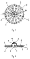
- Fig. 1 shows a bottom view of a spring pad, as in a number of four pieces per vehicle for the spring bearings of the Rear axle of a passenger car is provided.
- the Spring pad essentially consists of a disc-shaped, circular elastomeric body 2, in which a reinforcing insert 4 is embedded in the form of a plastic disc (see Fig. 2).
- the underside of the spring pad points to reduce their weight twelve recesses 1 and one same number of water drainage grooves 3.
- In the center of the elastomeric body 2 is one to the top of the spring pad pointing guide nose 5 formed, one from the bottom forms an accessible receiving space 10 for a metal cone. Bores 6 in the recesses 1 extend through the lower half of the elastomeric body 2 and have one production-related reason.
- Fig. 2 shows a cross section along the line A-A of Fig. 1. Based on this illustration, the location of the plastic reinforcement insert 4 and the leading nose 5 clearly.
- the reinforcement insert 4 is completely outside of the elastomeric material envelops.
- the guide lug 5 is used when installing the spring or damper leg positioning the torsion spring (not shown here) by the guide lug 5 axially in the Torsion spring engages.
- Receiving space 10 is arranged a metal cone 7 for reinforcement, which in turn is reinforced by struts 8, 9.
- the spring pad is around the reinforcement insert 4, which is made from a special plastic granulate, using a tool, a specially composed rubber compound sprayed and then with the application of heat and pressure vulcanized.
Landscapes
- Engineering & Computer Science (AREA)
- General Engineering & Computer Science (AREA)
- Mechanical Engineering (AREA)
- Springs (AREA)
- Vehicle Body Suspensions (AREA)
- Internal Circuitry In Semiconductor Integrated Circuit Devices (AREA)
- Surface Acoustic Wave Elements And Circuit Networks Thereof (AREA)
- Bipolar Transistors (AREA)
Description
- Fig. 1
- eine Unteransicht einer erfindungsgemäßen Federunterlage; und
- Fig. 2
- einen Querschnitt längs der Linie A-A der Fig. 1.
Claims (5)
- Federunterlage, insbesondere für das Federlager der Hinterachse eines Personenkraftwagens, mit einem scheibenförmigen Körper (2) aus elastomerem Material und mit einer in den elastomeren Körper (2) eingebetteten Verstärkungseinlage (4),
dadurch gekennzeichnet, daß
die Verstärkungseinlage (4) aus Kunststoff besteht. - Federunterlage nach Anspruch 1,
dadurch gekennzeichnet, daß
die Verstärkungseinlage (4) eine Scheibe ist. - Federunterlage nach Anspruch 1,
dadurch gekennzeichnet, daß
die Verstärkungseinlage (4) die Form eines Vielecks aufweist. - Federunterlage nach Anspruch 2 oder 3,
dadurch gekennzeichnet, daß
die Verstärkungseinlage (4) konvex ausgebildet ist. - Federunterlage nach Anspruch 2 oder 3,
dadurch gekennzeichnet, daß
die Verstärkungseinlage (4) konkav ausgebildet ist.
Applications Claiming Priority (2)
| Application Number | Priority Date | Filing Date | Title |
|---|---|---|---|
| DE29722552U | 1997-12-19 | ||
| DE29722552U DE29722552U1 (de) | 1997-12-19 | 1997-12-19 | Federunterlage |
Publications (3)
| Publication Number | Publication Date |
|---|---|
| EP0924445A2 EP0924445A2 (de) | 1999-06-23 |
| EP0924445A3 EP0924445A3 (de) | 2000-02-23 |
| EP0924445B1 true EP0924445B1 (de) | 2003-02-26 |
Family
ID=8050275
Family Applications (1)
| Application Number | Title | Priority Date | Filing Date |
|---|---|---|---|
| EP98121790A Expired - Lifetime EP0924445B1 (de) | 1997-12-19 | 1998-11-16 | Federunterlage |
Country Status (3)
| Country | Link |
|---|---|
| EP (1) | EP0924445B1 (de) |
| DE (2) | DE29722552U1 (de) |
| ES (1) | ES2191247T3 (de) |
Cited By (4)
| Publication number | Priority date | Publication date | Assignee | Title |
|---|---|---|---|---|
| CN101326382B (zh) * | 2005-12-14 | 2011-01-12 | 雷诺股份公司 | 可变挠性的弹簧支撑件 |
| DE102009045038A1 (de) | 2009-09-25 | 2011-03-31 | Lisa Dräxlmaier GmbH | Federunterlage und Verfahren zum Herstellen derselben |
| EP2466167A2 (de) | 2010-12-18 | 2012-06-20 | Audi AG | Federunterlage für eine freistehende Tragfeder eines Kraftfahrzeugs |
| WO2026046779A1 (en) * | 2024-08-29 | 2026-03-05 | Basf Polyurethanes Gmbh | Coil spring isolator and corresponding coil spring assembly |
Families Citing this family (8)
| Publication number | Priority date | Publication date | Assignee | Title |
|---|---|---|---|---|
| DE10009136A1 (de) | 2000-02-26 | 2001-08-30 | Volkswagen Ag | Federunterlage |
| DE10124976C2 (de) * | 2001-05-21 | 2003-11-06 | Daimler Chrysler Ag | Federunterlage |
| DE102007018160A1 (de) | 2007-04-18 | 2008-10-23 | Dr. Ing. H.C. F. Porsche Aktiengesellschaft | Lagerteller für eine Schraubenfeder eines Federbeines |
| DE102008050052A1 (de) | 2008-10-01 | 2010-04-08 | Audi Ag | Tragfeder eines Kraftfahrzeuges |
| DE102011106638A1 (de) | 2011-07-05 | 2012-01-26 | Daimler Ag | Federunterlage für Kraftfahrzeuge sowie Kraftfahrzeugfederelement |
| DE102012006741B4 (de) | 2012-04-04 | 2016-05-25 | Carl Freudenberg Kg | Federunterlage |
| DE102017219194A1 (de) * | 2017-10-26 | 2019-05-02 | Contitech Luftfedersysteme Gmbh | Schienenfahrwerk |
| CN110873140B (zh) * | 2019-11-18 | 2021-03-05 | 邹务丰 | 一种绳索传动发条弹簧组合弹性机构 |
Family Cites Families (6)
| Publication number | Priority date | Publication date | Assignee | Title |
|---|---|---|---|---|
| DE814363C (de) * | 1950-02-07 | 1951-09-20 | Ringfeder Gmbh | Feder |
| CH380546A (it) * | 1960-10-26 | 1964-07-31 | Gomma Antivibranti Applic | Rondella antivibrante in gomma per sospensioni a molla elicoidale |
| US3489402A (en) * | 1966-08-22 | 1970-01-13 | Btr Industries Ltd | Composite elastomeric springs |
| DE2005701A1 (en) * | 1970-02-07 | 1971-08-19 | Robert Bosch Gmbh, 7000 Stuttgart | Valve membrane with an annular, flexible reinforced body |
| DE2017999A1 (de) * | 1970-04-15 | 1971-10-28 | Jörn, Raoul, Dipl.-Ing., 8990 Lindau | Federelement, insbesondere zur elastischen Lagerung von Motoren |
| DE4007488A1 (de) * | 1990-03-09 | 1991-09-12 | Fichtel & Sachs Ag | Federbein fuer fahrzeuge |
-
1997
- 1997-12-19 DE DE29722552U patent/DE29722552U1/de not_active Expired - Lifetime
-
1998
- 1998-11-16 EP EP98121790A patent/EP0924445B1/de not_active Expired - Lifetime
- 1998-11-16 DE DE59807303T patent/DE59807303D1/de not_active Expired - Fee Related
- 1998-11-16 ES ES98121790T patent/ES2191247T3/es not_active Expired - Lifetime
Cited By (7)
| Publication number | Priority date | Publication date | Assignee | Title |
|---|---|---|---|---|
| CN101326382B (zh) * | 2005-12-14 | 2011-01-12 | 雷诺股份公司 | 可变挠性的弹簧支撑件 |
| DE102009045038A1 (de) | 2009-09-25 | 2011-03-31 | Lisa Dräxlmaier GmbH | Federunterlage und Verfahren zum Herstellen derselben |
| WO2011036177A1 (de) | 2009-09-25 | 2011-03-31 | Lisa Dräxlmaier GmbH | Federunterlage und verfahren zum herstellen derselben |
| DE102009045038B4 (de) * | 2009-09-25 | 2012-05-24 | Lisa Dräxlmaier GmbH | Federunterlage und Verfahren zum Herstellen derselben |
| EP2466167A2 (de) | 2010-12-18 | 2012-06-20 | Audi AG | Federunterlage für eine freistehende Tragfeder eines Kraftfahrzeugs |
| DE102010055141A1 (de) | 2010-12-18 | 2012-08-02 | Audi Ag | Federunterlage für eine freistehende Tragfeder eines Kraftfahrzeugs |
| WO2026046779A1 (en) * | 2024-08-29 | 2026-03-05 | Basf Polyurethanes Gmbh | Coil spring isolator and corresponding coil spring assembly |
Also Published As
| Publication number | Publication date |
|---|---|
| EP0924445A3 (de) | 2000-02-23 |
| EP0924445A2 (de) | 1999-06-23 |
| DE29722552U1 (de) | 1998-02-19 |
| DE59807303D1 (de) | 2003-04-03 |
| ES2191247T3 (es) | 2003-09-01 |
Similar Documents
| Publication | Publication Date | Title |
|---|---|---|
| DE19628651C2 (de) | Elastische Halterung mit zwei axial zusammengedrückten Elementen | |
| EP0924445B1 (de) | Federunterlage | |
| DE19825311C1 (de) | Fahrzeugrad mit einem Notlaufstützkörper | |
| DE3217959A1 (de) | Vorrichtung zur vibrationsisolierten befestigung eines fahrschemels oder aggregathalters | |
| DE69008264T2 (de) | Verbesserungen an hydraulischen Schwingungsdämpfern. | |
| WO1997030297A1 (de) | Lagerbuchse | |
| DE4104859C1 (de) | ||
| DE102016200307A1 (de) | Federteller für einen Schwingungsdämpfer | |
| EP0351737B1 (de) | Hydraulisch dämpfendes Motorlager | |
| DE2739597C2 (de) | Kraftfahrzeugrad | |
| DE69407331T2 (de) | Befestigungselement für die Verbindung einer Feder-Stossdämpfereinheit an einem Fahrzeugaufbau | |
| DE19625106C2 (de) | Schwingungsdämpfer mit kurzer Einbaulänge | |
| EP0168767B1 (de) | Federkörper für die Dämpfung von Schwingungen | |
| EP0734888A1 (de) | Oberes Federbeinstützlager für Radaufhängungen in einem Kraftfahrzeug | |
| DE69811118T2 (de) | Schwingungsdämpfender ring für die radaufhängung eines kraftfahrzeuges | |
| DE102005012751B4 (de) | Gelenklagerbuchse, insbesondere für einen Achslenker eines Kraftfahrzeugs | |
| DE19945841A1 (de) | Gummi-Metall-Element | |
| EP0699847B1 (de) | Drehschwingungstilger, insbesondere für den Antriebsstrang von Kraftfahrzeugen | |
| DE3512555C2 (de) | Schallisolierendes Lager | |
| DE102017010009B4 (de) | Elastomer-Metall-Lager | |
| DE102017215403B4 (de) | Federbaugruppe | |
| DE19620835B4 (de) | Hydraulikaufbau | |
| DE8235995U1 (de) | Federnder Träger für einen Stoßdämpfer einer vorderen Federung eines Fahrzeugs | |
| DE102017010006B4 (de) | Elastomer-Metall-Lager | |
| DE102017215348A1 (de) | Luftfederbein mit Akustiklager |
Legal Events
| Date | Code | Title | Description |
|---|---|---|---|
| PUAI | Public reference made under article 153(3) epc to a published international application that has entered the european phase |
Free format text: ORIGINAL CODE: 0009012 |
|
| AK | Designated contracting states |
Kind code of ref document: A2 Designated state(s): DE ES FR GB IT |
|
| AX | Request for extension of the european patent |
Free format text: AL;LT;LV;MK;RO;SI |
|
| PUAL | Search report despatched |
Free format text: ORIGINAL CODE: 0009013 |
|
| AK | Designated contracting states |
Kind code of ref document: A3 Designated state(s): AT BE CH CY DE DK ES FI FR GB GR IE IT LI LU MC NL PT SE |
|
| AX | Request for extension of the european patent |
Free format text: AL;LT;LV;MK;RO;SI |
|
| RIC1 | Information provided on ipc code assigned before grant |
Free format text: 7F 16F 1/12 A |
|
| 17P | Request for examination filed |
Effective date: 20000322 |
|
| AKX | Designation fees paid |
Free format text: DE ES FR GB IT |
|
| GRAG | Despatch of communication of intention to grant |
Free format text: ORIGINAL CODE: EPIDOS AGRA |
|
| RAP1 | Party data changed (applicant data changed or rights of an application transferred) |
Owner name: TRELLEBORG AUTOMOTIVE TECHNICAL CENTRE GMBH |
|
| 17Q | First examination report despatched |
Effective date: 20020212 |
|
| GRAG | Despatch of communication of intention to grant |
Free format text: ORIGINAL CODE: EPIDOS AGRA |
|
| GRAH | Despatch of communication of intention to grant a patent |
Free format text: ORIGINAL CODE: EPIDOS IGRA |
|
| GRAH | Despatch of communication of intention to grant a patent |
Free format text: ORIGINAL CODE: EPIDOS IGRA |
|
| GRAA | (expected) grant |
Free format text: ORIGINAL CODE: 0009210 |
|
| AK | Designated contracting states |
Designated state(s): DE ES FR GB IT |
|
| REG | Reference to a national code |
Ref country code: GB Ref legal event code: FG4D Free format text: NOT ENGLISH |
|
| GBT | Gb: translation of ep patent filed (gb section 77(6)(a)/1977) |
Effective date: 20030226 |
|
| REF | Corresponds to: |
Ref document number: 59807303 Country of ref document: DE Date of ref document: 20030403 Kind code of ref document: P |
|
| REG | Reference to a national code |
Ref country code: ES Ref legal event code: FG2A Ref document number: 2191247 Country of ref document: ES Kind code of ref document: T3 |
|
| ET | Fr: translation filed | ||
| PLBE | No opposition filed within time limit |
Free format text: ORIGINAL CODE: 0009261 |
|
| STAA | Information on the status of an ep patent application or granted ep patent |
Free format text: STATUS: NO OPPOSITION FILED WITHIN TIME LIMIT |
|
| 26N | No opposition filed |
Effective date: 20031127 |
|
| PGFP | Annual fee paid to national office [announced via postgrant information from national office to epo] |
Ref country code: GB Payment date: 20051117 Year of fee payment: 8 |
|
| PGFP | Annual fee paid to national office [announced via postgrant information from national office to epo] |
Ref country code: FR Payment date: 20051118 Year of fee payment: 8 |
|
| PGFP | Annual fee paid to national office [announced via postgrant information from national office to epo] |
Ref country code: ES Payment date: 20051122 Year of fee payment: 8 |
|
| PGFP | Annual fee paid to national office [announced via postgrant information from national office to epo] |
Ref country code: DE Payment date: 20061127 Year of fee payment: 9 |
|
| PGFP | Annual fee paid to national office [announced via postgrant information from national office to epo] |
Ref country code: IT Payment date: 20061130 Year of fee payment: 9 |
|
| GBPC | Gb: european patent ceased through non-payment of renewal fee |
Effective date: 20061116 |
|
| REG | Reference to a national code |
Ref country code: FR Ref legal event code: ST Effective date: 20070731 |
|
| PG25 | Lapsed in a contracting state [announced via postgrant information from national office to epo] |
Ref country code: GB Free format text: LAPSE BECAUSE OF NON-PAYMENT OF DUE FEES Effective date: 20061116 |
|
| REG | Reference to a national code |
Ref country code: ES Ref legal event code: FD2A Effective date: 20061117 |
|
| PG25 | Lapsed in a contracting state [announced via postgrant information from national office to epo] |
Ref country code: FR Free format text: LAPSE BECAUSE OF NON-PAYMENT OF DUE FEES Effective date: 20061130 Ref country code: ES Free format text: LAPSE BECAUSE OF NON-PAYMENT OF DUE FEES Effective date: 20061117 |
|
| PG25 | Lapsed in a contracting state [announced via postgrant information from national office to epo] |
Ref country code: DE Free format text: LAPSE BECAUSE OF NON-PAYMENT OF DUE FEES Effective date: 20080603 |
|
| PG25 | Lapsed in a contracting state [announced via postgrant information from national office to epo] |
Ref country code: IT Free format text: LAPSE BECAUSE OF NON-PAYMENT OF DUE FEES Effective date: 20071116 |