EP0924034A2 - Roboter und Verfahren zur Steuerung dieses Roboters - Google Patents
Roboter und Verfahren zur Steuerung dieses Roboters Download PDFInfo
- Publication number
- EP0924034A2 EP0924034A2 EP98310305A EP98310305A EP0924034A2 EP 0924034 A2 EP0924034 A2 EP 0924034A2 EP 98310305 A EP98310305 A EP 98310305A EP 98310305 A EP98310305 A EP 98310305A EP 0924034 A2 EP0924034 A2 EP 0924034A2
- Authority
- EP
- European Patent Office
- Prior art keywords
- component units
- robot
- unit
- operation program
- prescribed
- Prior art date
- Legal status (The legal status is an assumption and is not a legal conclusion. Google has not performed a legal analysis and makes no representation as to the accuracy of the status listed.)
- Ceased
Links
- 238000000034 method Methods 0.000 title claims description 11
- 230000006870 function Effects 0.000 abstract description 7
- 230000015654 memory Effects 0.000 description 87
- 230000006399 behavior Effects 0.000 description 12
- AHVPOAOWHRMOBY-UHFFFAOYSA-N 2-(diethylamino)-1-[6,7-dimethoxy-1-[1-(6-methoxynaphthalen-2-yl)ethyl]-3,4-dihydro-1h-isoquinolin-2-yl]ethanone Chemical compound C1=C(OC)C=CC2=CC(C(C)C3C4=CC(OC)=C(OC)C=C4CCN3C(=O)CN(CC)CC)=CC=C21 AHVPOAOWHRMOBY-UHFFFAOYSA-N 0.000 description 10
- 210000002414 leg Anatomy 0.000 description 9
- 210000000689 upper leg Anatomy 0.000 description 8
- 238000010586 diagram Methods 0.000 description 7
- 230000009471 action Effects 0.000 description 6
- 238000004891 communication Methods 0.000 description 5
- 230000015572 biosynthetic process Effects 0.000 description 4
- 230000008859 change Effects 0.000 description 4
- 238000010276 construction Methods 0.000 description 4
- 238000005755 formation reaction Methods 0.000 description 4
- 230000002093 peripheral effect Effects 0.000 description 3
- 238000013461 design Methods 0.000 description 2
- 230000000694 effects Effects 0.000 description 2
- 230000007246 mechanism Effects 0.000 description 2
- 238000012986 modification Methods 0.000 description 2
- 230000004048 modification Effects 0.000 description 2
- 230000008901 benefit Effects 0.000 description 1
- 238000001514 detection method Methods 0.000 description 1
- 230000002068 genetic effect Effects 0.000 description 1
- 230000005484 gravity Effects 0.000 description 1
- 230000002452 interceptive effect Effects 0.000 description 1
- 230000008569 process Effects 0.000 description 1
- 238000012545 processing Methods 0.000 description 1
Images


Classifications
-
- B—PERFORMING OPERATIONS; TRANSPORTING
- B25—HAND TOOLS; PORTABLE POWER-DRIVEN TOOLS; MANIPULATORS
- B25J—MANIPULATORS; CHAMBERS PROVIDED WITH MANIPULATION DEVICES
- B25J9/00—Programme-controlled manipulators
- B25J9/16—Programme controls
- B25J9/1602—Programme controls characterised by the control system, structure, architecture
-
- B—PERFORMING OPERATIONS; TRANSPORTING
- B25—HAND TOOLS; PORTABLE POWER-DRIVEN TOOLS; MANIPULATORS
- B25J—MANIPULATORS; CHAMBERS PROVIDED WITH MANIPULATION DEVICES
- B25J9/00—Programme-controlled manipulators
- B25J9/16—Programme controls
- B25J9/1615—Programme controls characterised by special kind of manipulator, e.g. planar, scara, gantry, cantilever, space, closed chain, passive/active joints and tendon driven manipulators
- B25J9/1617—Cellular, reconfigurable manipulator, e.g. cebot
Definitions
- This invention relates to robot devices and to driving control methods for such robot devices, such as may be applied to autonomous moving type robots.
- FIG. 1A A variety of robots have been proposed such as a four-footed walking type as illustrated in Fig. 1A of the accompanying drawings, a two-footed walking type as illustrated in Fig. 1B, a vehicle type as illustrated in Fig. 1C and a two-wheel driving type as illustrated in Fig. 1D.
- these kinds of robots operate in accordance with their configurations by executing an operation program corresponding to the configurations, such as the two-footed walking type or the four-footed walking type, by a general purpose computer accommodated in a body unit or a central processing unit (CPU) mounted on a CPU board.
- an operation program corresponding to the configurations, such as the two-footed walking type or the four-footed walking type, by a general purpose computer accommodated in a body unit or a central processing unit (CPU) mounted on a CPU board.
- CPU central processing unit
- component units such as a body unit and a head unit, for forming the robot are connected together using serial buses and thereby, the CPU detects the connecting mechanisms of these component units in order to automatically decide the configuration of the robot based on the detection result.
- one of this type of robots divides an operation program into a host program (hereinafter, referred to as a host operation program) for supplying a general operation instruction such as "move forward", “move backward”, etc. which does not depend on the configuration of the robot and a subordinate program (hereinafter, referred to as a subordinate operation program) for driving and controlling the component units to respective states depending on the configuration of the robot in order to actually move the robot in accordance with the above instruction.
- a host operation program which does not depend on the configuration of the robot, can be utilized commonly between different robots.
- a CPU classifies the configuration of the robot and it is decided based on the classification result how operation program is selected, that is to say, what purpose (for instance, right foot or left foot) the component units are operated for. Accordingly, even when the configuration of the robot is changed by changing the connecting mechanism of the component units, an operation program corresponding to the configuration can be automatically selected and executed.
- a method has been considered in which a CPU board is detachably mounted in a body unit using a parallel bus such as a Versa Module Europe (VME) bus or a peripheral component interconnect (PCI) bus.
- VME Versa Module Europe
- PCI peripheral component interconnect
- One aspect of the invention provides a robot device constructed by connecting plural component units together, comprising control means which is detachably mounted on a prescribed component unit, for driving and controlling each of the component units in a prescribed state.
- control means can be easily exchanged.
- a robot device which is constructed by connecting plural component units together, comprises storing means which is detachably mounted on a prescribed component unit and used for storing desired behaviour type information.
- the storing means can be readily exchanged for storing means in which different behaviour type information is stored.
- a robot device constructed by connecting plural component units together comprises first storing means for storing configuration information which represents a configuration of the robot device constructed by connecting the component units together with unit information inherent in each component unit; second storing means for storing a prescribed operation program; and control means for reading out the configuration information and the operation program from the first and the second storing means respectively, changing the read configuration information in accordance with additional component units connected to respective component units, and driving and controlling each of the component units and additional component units in a prescribed state on the basis of the changed configuration information and operation program.
- the configuration information and the operation program do not need to be rewritten and the control means can be used as it is without changing in order to drive and control each of the component units in a prescribed state.
- the configuration of the robot can be changed with ease.
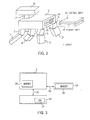
- Fig. 2, 1 designates a robot according to a first embodiment as a whole, which is monolithically constructed; thigh units 3 to 6 and leg units 7 to 10 are successively connected to the front, rear, right and left corner parts below a body unit 2 respectively, and a neck unit 11 and a head unit 12 are successively connected to the central part of a front end part on the upper surface of the body unit 2.
- the body unit 2, the thigh units 3 to 6, the leg units 7 to 10, the neck unit 11 and the head unit 12 are called component units 2 to 12 collectively.
- first and second slots 2A and 2B are provided on the side surface of the rear end side of the body unit 2.
- a control unit 15 composed of a personal computer (PC) card is detachably mounted in the first slot 2A and a memory unit 16 composed of a PC card is detachably mounted in the second slot 2B.
- PC personal computer
- a CPU 17 or the like for controlling the action of the robot 1 is accommodated in the control unit 15.
- a nonvolatile memory (hereinafter, referred to as a memory) 18, such as a mask read only memory (ROM) or a flash ROM. is accommodated in the memory unit 16.
- ROM mask read only memory
- a flash ROM flash ROM
- the body unit 2 contains a memory 19 such as a flash ROM.
- a basic operation program an operation program (hereinafter, referred to as a basic operation program) and a configuration program are previously stored: the basic operation program for making the robot 1 perform a basic action, which is composed of a hierarchical structure comprising a host operation program and a program (hereinafter, referred to as an intermediate operation program) being a part of a subordinate operation program to supply an action instruction, such as "stand up” and "sit down", depending on an operation instruction supplied from the host operation program; and the configuration information for representing various kinds of information (hereinafter, referred to as unit information collectively), such as a role ("head", "neck”, etc.), a formation and a position of the center of gravity, for each of the component units 2 to 12 with a tree structure showing the connecting condition of the component units 2 to 12, as shown in Fig. 3, in accordance with the configuration of the robot 1 (for example, a four-foot walking type).
- the CPU 17 reads the configuration information and the basic operation program from the memory 19 of the body unit 2 and the application program from the memory 18 of the memory unit 16 so as to make the robot 1 drive according to its configuration and behavior types based on the read configuration information, the basic operation program and the application program.
- an serial bus host (SBH) 26 for controlling a serial bus in the body unit 2 and the memory 18 in the memory unit 16 are electrically connected to the CPU 17 of the control unit 15 via a first CPU bus 21, a bus use switcher 22, a second CPU bus 23, a card bus interface 24 and a card bus 20 sequentially.
- the memory 19 is electrically connected to the SBH 26 via a HUB (distributor) 27 in the body unit 2.
- a battery 31 in the body unit 2 is electrically connected to a battery manager 30 of the control unit 15 through the card bus 20.
- OS operating system
- SDRAM SD-random access memory
- the CPU 17 reads out the configuration information from the memory 19 via the HUB 27 and the SBH 26 in the body unit 2 and then, downloads the read configuration information to the SDRAM 36 via the HUB 27, the SBH 26, the card bus 20, the card bus interface 24, the second CPU bus 23 and the SDRAM interface 35 successively.
- the CPU 17 reads out the configuration information from the SDRAM 36 via the first CPU bus 21 to recognize the configuration of the robot 1 based on the read configuration information.
- the bus use switcher 22 gives the using right for the second CPU bus 23 to a direct memory access (DMA) controller 37 under the control of the CPU 17, so that the DMA controller 37 reads out the application program from the memory 18 in the memory unit 16 under the control of the CPU 17 and downloads the read application program to the SDRAM 36 via the card bus 20, the card bus interface 24, the second CPU bus 23 and the SDRAM interface 35 successively.
- DMA direct memory access
- the CPU 17 reads out the application program from the SDRAM 36 through the first CPU bus 21 to recognize the behavior type of the robot 1 based on the read application program.
- the CPU 17 reads out the basic operation program from the memory 19 in the body unit 2 through a route similar to the aforementioned case of reading the configuration information, downloads the read basic operation program to the SDRAM 36 and then, reads out the basic operation program from the SDRAM 36 through the first CPU bus 21 to start it.
- the CPU 17, when receiving a prescribed instruction such as "move forward" from the host operation program of the basic operation program, generates control signals S1 corresponding to various kinds of instructions, such as "raise a right leg", which are necessary for the respective component units 3 to 12 except for the body unit 2 in order to move the robot 1 forward based on the intermediate operation program of the basic operation program and the configuration information, and supplies these control signals S1 to the HUB 27 via the SBH 26 in the body unit 2.
- HUBs 40 accommodated in the respective thigh parts 3 to 6 and the neck part 11 are electrically connected to the HUB 27 of the body unit 2 through serial buses 41 and moreover, HUBs 40 housed in the respective leg units 7 to 10 and the head unit 12 are electrically connected to the HUBs 40 in the thigh units 3 to 6 and the neck unit 11 through serial buses 41, respectively.
- control signals S1 supplied to the HUB 27 of the body unit 2 are supplied from the HUB 27 to the corresponding electronic parts 43 through the respective HUBs of the thigh units 3 to 6, the leg units 7 to 10, the neck unit 11 and the head unit 12.
- the CPU 17 controls and drives the electronic parts 43 in the thigh units 3 to 6, the leg units 7 to 10, the neck unit 11 and the head unit 12 based on the corresponding control signals S1.
- each of the thigh units 3 to 6, the leg units 7 to 10, the neck unit 11 and the head unit 12 can perform required actions, for example, for moving the robot 1 forward.
- a parallel input/output (PIO) 55 or a serial communication control (SCC) 56 connected to the second CPU bus 23 through the peripheral interface 32 is electrically connected to an corresponding external terminal 57A or 57B provided in the body unit 2 through the card bus 20.
- the robot 1 can execute a debugging process in the control unit 15, for example, using a personal computer (not shown) which can be connected to the external terminal 57A or the 57B, through the parallel input/output 55 or the serial communication control 56.
- a personal computer not shown
- the robot 1 can execute a debugging process in the control unit 15, for example, using a personal computer (not shown) which can be connected to the external terminal 57A or the 57B, through the parallel input/output 55 or the serial communication control 56.
- control unit 15 is provided with a timer 58 connected to the second CPU bus 23.
- the timer 58 is used when an interactive operation is necessary for operation of the CPU 17.
- control unit 15 and the memory unit 16 are mounted in the first and second slot 2A and 2B of the body unit 2 respectively, so that the CPU 17 of the control unit 15 reads out the application program from the memory 18 of the memory unit 16 and also reads out the configuration information and the basic operation program from the memory 19 in the body unit 2.
- the CPU 17 recognizes the configuration of the robot 1 based on the configuration information as well as the behavior type of the robot 1 based on the application program. Under this state, the CPU 17 drives and controls the electronic parts 43 of the respective component units 3 to 12 based on the basic operation program and the configuration information, in order to perform operations corresponding to instructions supplied from the host program of the basic operation program.
- the basic operation program is stored in the memory 19 in the body unit 2 and only the operation system is stored in the memory 33 in the control unit 15 which is detachably attached to the body unit 2. Therefore, even when the control unit 15 is exchanged for a new one, the basic operation program does not need to be downloaded to a memory 33 in a new control unit 15.
- the existing control unit 15 can be exchanged for a control unit in which a CPU whose performance is improved is accommodated.
- control unit 15 since only the operation system is stored in the memory 33 of the control unit 15 as stated above, the control unit 15 can be used for other robots. Therefore, the general purpose of the control unit 15 can be improved.
- the robot 1 can drive and control the component units 3 to 12 except for the body unit 2 in the respective prescribed states based on the configuration information and the intermediate operation program, so that the structure of the basic operation program can be more simplified than that of the operation program having a hierarchical structure comprising the host operation program and the subordinate operation program.
- the memory unit 16 can be readily exchanged for a new one similarly to the control unit 15.
- the robot 1 can perform an action of different kind of behavior type only by mounting a memory unit 16 having different kind of behavior type information in the second slot 2B of the body unit 2
- the configuration information and the basic operation program are stored in the memory 19 of the body unit 2 and the configuration information and the basic operation program are read out from the CPU 17 of the control unit 15, which is detachably mounted in the first slot 2A of the body unit 2, at the time of operation of the robot 1.
- the control unit 15 can be readily exchanged for a new control unit in which a CPU whose performance is improved is accommodated and thus, the robot capable of simply improving its performance and functions can be realized.
- the memory unit 16 is also detachably mounted and held in the second slot 2B of the body unit 2 similarly to the body unit 15, so that the memory unit 16 can be readily exchanged for a memory unit 16 which contains a memory 18 storing behavior type information different from that of stored in the memory 18 of the former memory unit 16. Accordingly, a robot capable of simply improving its functions and performance can be realized.
- Fig. 7 in which the same reference numerals are applied to parts corresponding to Fig. 2 shows a robot 50 according to a second embodiment.
- the robot 50 is constructed substantially similarly to the robot 1 according to the first embodiment except that prescribed component units (hereinafter, referred to as additional component units) 52, such as a tail unit, are newly and detachably connected to connection parts 51A provided at plural prescribed positions of a body unit 51 in addition to the component units 3 to 12 except for the body unit 51 and that configuration information is changed by a control unit 53 in accordance with the connections of the additional component units 52.
- additional component units such as a tail unit
- the body unit 51 has a memory 54 in which the positional information of a connection point P1 corresponding to each connection part 51A of an HUB 55 is stored in addition to the basic operation program and the configuration information (indicating the configuration of the robot 50 before connecting the additional component units 52) and a connector (not shown) connected to the HUB 55 through a serial bus 41 provided in each of the connection parts 51A.
- Each additional component unit 52 contains an HUB 40 and electronic parts 43 similarly to the component units 3 to 12 except for the body unit 51 and has a connector (not shown) connected to the HUB 40 with a serial bus 41.
- the additional component unit 52 is physically connected to the corresponding connection part 51A of the body unit 51, so that the HUB 40 can be electrically connected to the HUB 55 of the body unit 51 with the serial bus 41.
- the additional component unit 52 contains a nonvolatile memory 56, such as a mask ROM or a flash ROM, storing unit information corresponding to the additional component unit 52.
- a nonvolatile memory 56 such as a mask ROM or a flash ROM
- the robot 50 when the control unit 53 is mounted in the first slot of the body unit 51 to start the CPU 57 of the control unit 53 and an operation system read out from a memory 33, reads out the configuration information and the positional information from a memory 54 in the body unit 51 to download them to an SDRAM 36, and reads out the unit information stored in the memory 56 of the additional component unit 52 via an SBH 26, an HUB 55 and a serial bus 41 of the body unit 51 and the HUB 40 of the additional component unit 52 successively to download it to the SDRAM 36.
- the CPU 57 reads out the downloaded configuration formation, positional information and unit information from the SDRAM 36 and changes a tree structure according to the configuration of the robot 50 before connecting the additional component units 52 to the body unit 51 to a tree structure according to the configuration of the robot 50 after connecting the additional component units 52 to the body unit 51, based on these read configuration information, positional information and unit information, in order to change the configuration information.
- the CPU 57 can recognize as to which additional component unit 52 is connected to which connection part 51A of the body unit 51 and as to how the configuration of the robot 50 is resultantly changed, based on thus changed configuration information (hereinafter, referred to as changed configuration information).
- the CPU 57 downloads the changed configuration information to the SDRAM 36 and also downloads the basic operation program to the SDRAM 36 by reading out it from the memory 54 in the body unit 51.
- the CPU 57 reads out the changed configuration information from the SDRAM 36 and also reads out the basic operation program to start it.
- the CPU 57 when receiving a prescribed instruction, such as "move forward", from the host operation program of the basic operation program, the CPU 57 generates control signals S2 according to various kinds of instructions, such as "raise a right leg", which are necessary for the respective component units 3 to 12 except for the body unit 51 and the additional component units 52 in order to move the robot 50 forward, based on the intermediate operation program of the basic operation program and the changed configuration information and supplies these control signals S2 to the respective component units 3 to 12 except for the body unit 51 and the additional component units 52 from the HUB 27 of the body unit 51.
- the CPU 57 drives and controls the electronic parts 43 of the component units 3 to 12 except for the body unit 51 and the additional component units 52 based on the corresponding control signals S2. Therefore, the respective component units 3 to 12 except for the body unit 51 and the additional component units 52 can perform respective required actions for moving the robot 1 forward.
- the CPU 57 in the control unit 53 changes the configuration information to changed configuration information according to the configuration of the robot 50 after connecting the additional component units 52 to the body unit 51, based on the configuration information and positional information read from the memory of the body unit 51 and the unit information read from the memory 56 of the additional component units 52 connected to the body unit 51.
- the CPU 57 drives and controls the electronic parts 43 of the component units 3 to 12 except for the body unit 51 and the additional component units 52 based on the basic operation program and the configuration information, so that the robot 50 whose configuration is changed operates depending on instructions supplied from the host program of the basic operation program.
- the control unit 53 can be simply exchanged for a new control unit without downloading the basic operation program to a memory 33 at the time of changing the control unit 53.
- this robot 50 even when the additional component units 52 are connected to the body unit 51 to change the configuration of the robot 50, it is not necessary to download a basic operation program according to a new configuration of the robot 50 to the memory 33 of the control unit 53, so that the configuration of the robot 50 can be changed with ease.
- one control unit 53 can readily cope with the change of configuration of the robot 50 and can also be simply applied to other robots regardless of the configurations of the robots. Therefore, the generalization of the control unit 53 can be more improved than that of the robot 1 (Fig. 2) according to the aforementioned first embodiment.
- the configuration information and the basic operation program are stored in the memory 54 of the body unit 51 and the configuration information and the basic operation program are read out from the memory 54 in the body unit 51 by the control unit 53 detachably mounted in the first slot of the body unit 51 so that the robot 50 is operated based on the read configuration information and basic operation program and thereby, the control unit 53 can be readily exchanged.
- the control unit 53 detachably mounted in the first slot of the body unit 51 so that the robot 50 is operated based on the read configuration information and basic operation program and thereby, the control unit 53 can be readily exchanged.
- a robot capable of simply improving its functions and performance can be realized.
- the configuration information is changed in accordance with this change. Therefore, the configuration of the robot 50 can be simply changed and a robot capable of simply improve its function and performance can be realized.
- the present invention is applied to the four-foot walking type robot 1, 50.
- the present invention is not limited thereto but can be applied to robots with other kinds of configurations such as a two-foot walking type, a vehicle type, a two-wheeled driving type or modified types of them.
- control unit 15, 53 and the memory unit 16 mounted in the first and second slots 2A and 2B of the body unit 2, 51 are electrically connected together with the card bus 20 in the body unit 2, 51.
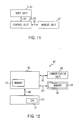
- the present invention is not limited thereto but the body unit 2, 51, the control unit 15, 53 and the memory part 16 can be connected in series as shown in Fig. 11.
- the CPU 17, 57 operate the robot 1 in accordance with operation instructions supplied from the host program of the basic operation program.
- a third slot (not shown) can be provided on the body unit 81 of a robot 80 in addition to the first and second slots as shown in Fig. 12 in which the same reference numerals are applied to parts corresponding to Fig. 3, a communication unit 82 which is composed of a PC card and which contains a radio local area network (LAN) can detachably be mounted in the third slot in order to electrically connect the communication unit 82 to the control unit 15 with the card bus 20, so that the CPU 17 can operate the robot 80 based on operation instructions obtained from the outside via the communication unit 82.
- the robot can be operated based on operation instructions obtained from the outside using other various media, such as the case where the CPU 17, 57 can operate the robot based on operation instructions obtained from the outside with ethernet or the like.
- control unit 15, 53, the memory unit 16 and the body unit 2, 51 are electrically connected together with the card bus 20.
- the present invention is not limited thereto but the control unit 15, 53, the memory unit 16 and the body unit 2, 51 can be electrically connected together with buses having other various types structures in place of the card bus 20.
- the basic operation program and the configuration information are previously stored in the memory 19 in the body unit 2.
- the present invention is not limited thereto but the operation program having a hierarchical structure comprising the host operation program and the subordinate operation program can be previously stored in the memory 19 in the body unit 2 and the robot 1 can be actuated by the CPU 17 only based on the operation program without employing the configuration information.
- the basic operation program having a hierarchical structure comprising the host operation program and the intermediate operation program is previously stored in the memory 19, 54 in the body unit 2, 51.
- the present invention is not limited thereto but the intermediate operation program of the basic operation program can be previously stored in the memory 19, 54 in the body unit 2, 51, and the host operation program of the basic operation program can be previously stored in the memory 18 in the memory unit 16.
- the basic operation program is previously stored in the memory 19, 54 in the body unit 2, 51.
- the present invention is not limited thereto but the basic operation program stored in the memory 19, 54 in the body unit 2, 51 can be rewritten as required.
- the robot 1 is operated by the CPU 17, 57 of the control unit 15, 53 based on the basic operation program and the configuration information.
- the control unit can be provided with a learning function for learning operations as the robot repeats a variety of operations and the basic operation program and the configuration information can be rewritten based on the learning result.
- the basic operation program and/or the configuration information which is rewritten based on the learning result, can be mated with the basic operation program and/or the configuration information similarly rewritten based on the learning result of a robot having the same configuration or a different configuration, by using a genetic algorithm.
- the memory 19, 54 previously storing the basic operation program and the configuration information is accommodated in the body unit 2, 51.
- the present invention is not limited thereto but the memory 19, 54 can be accommodated in any of the component units 3 to 12 except for the body unit 2, 51 or the additional component units 52, or a memory in which only the basic operation program is previously stored and a memory in which the configuration information is previously stored can be accommodated in respectively different any of the component units 2 to 12 or in the additional component units 52, as long as the memory 19, 54 in which the basic operation program and the configuration are previously stored can electrically connected to the control unit 15, 53.
- the memory unit 16 containing a memory in which behavior type information is stored is mounted in the second slot 2B of the body unit 2, 51.
- the present invention is not limited thereto but and a memory unit containing an extending memory can be mounted in the second slot 2B of the body unit 2, 51 in place of the memory unit 16 and various kinds of information can be stored in the extending memory of the memory unit as desired.
- connection parts 51A are provided on the body unit 51.
- connection parts can be provided not only on the body unit 51 but also on the component units 3 to 12 except for the body unit 51 to connect the additional component units 52 thereto.
- the basic operation program is previously stored in the memory 54 in the body unit 51.
- the present invention is not limited thereto but plural basic operation programs according to various configurations of the robot 50 can be previously stored in the memory of the memory unit 16, so that a basic operation program according to configuration information changed depending on the connection of the additional component unit 52 to the body unit 51 is selected from these basic operation programs to be used.
- control unit 15, 53 is used, which is monolithically and detachably held in a prescribed component unit as control means for driving and controlling the component units in respective prescribed states.
- control unit 15, 53 is monolithically and detachably held in a prescribed component unit as control means for driving and controlling the component units in respective prescribed states.
- present invention is not limited thereto but other control means having various types of formations or configurations can be used as long as the control means can be detachably held in a prescribed component unit.
- the memory unit 16 is applied, which is monolithically and detachably mounted in a prescribed component unit as storing means for storing desired behaviour type information.
- the present invention is not limited thereto but storing means having various kinds of formations or configurations can be used as long as the storing means can be detachably mounted in a prescribed component unit.
Applications Claiming Priority (2)
| Application Number | Priority Date | Filing Date | Title |
|---|---|---|---|
| JP35393597A JP3765356B2 (ja) | 1997-12-22 | 1997-12-22 | ロボツト装置 |
| JP35393597 | 1997-12-22 |
Publications (2)
| Publication Number | Publication Date |
|---|---|
| EP0924034A2 true EP0924034A2 (de) | 1999-06-23 |
| EP0924034A3 EP0924034A3 (de) | 2004-04-14 |
Family
ID=18434218
Family Applications (1)
| Application Number | Title | Priority Date | Filing Date |
|---|---|---|---|
| EP98310305A Ceased EP0924034A3 (de) | 1997-12-22 | 1998-12-16 | Roboter und Verfahren zur Steuerung dieses Roboters |
Country Status (11)
| Country | Link |
|---|---|
| US (2) | US6321140B1 (de) |
| EP (1) | EP0924034A3 (de) |
| JP (1) | JP3765356B2 (de) |
| KR (1) | KR100601738B1 (de) |
| CN (1) | CN1096920C (de) |
| AU (1) | AU762795B2 (de) |
| BR (1) | BR9805614A (de) |
| CA (1) | CA2255574A1 (de) |
| HK (1) | HK1023746A1 (de) |
| MY (1) | MY118860A (de) |
| SG (1) | SG94714A1 (de) |
Cited By (20)
| Publication number | Priority date | Publication date | Assignee | Title |
|---|---|---|---|---|
| EP1072365A1 (de) * | 1999-07-28 | 2001-01-31 | Yamaha Hatsudoki Kabushiki Kaisha | Steuerungssystem für eine modulare Maschine |
| WO2001014033A1 (fr) * | 1999-08-24 | 2001-03-01 | Kabushiki Kaisha Bandai | Jouet electronique |
| WO2001032366A1 (fr) * | 1999-10-29 | 2001-05-10 | Sony Corporation | Systeme robot, dispositif de robot et sa garniture |
| WO2001048689A1 (fr) * | 1999-12-28 | 2001-07-05 | Sony Corporation | Systeme de transmission d'informations, procede de transmission d'informations, robot, support d'enregistrement d'informations, systeme de vente en ligne, procede de vente en ligne et serveur de vente |
| WO2001050362A1 (fr) * | 1999-12-30 | 2001-07-12 | Sony Corporation | Systeme et procede d'achat, dispositif et procede d'acceptation de commandes et programme informatique |
| WO2001050265A1 (fr) * | 1999-12-30 | 2001-07-12 | Sony Corporation | Systeme, appareil et procede de diagnostic |
| EP1120205A1 (de) * | 1999-01-25 | 2001-08-01 | Sony Corporation | Roboter |
| WO2001059642A1 (fr) * | 2000-02-10 | 2001-08-16 | Sony Corporation | Systeme de fourniture d'informations, dispositif de fourniture d'informations et systeme de commande d'un dispositif robot |
| US6462498B1 (en) | 2000-05-09 | 2002-10-08 | Andrew J. Filo | Self-stabilizing walking apparatus that is capable of being reprogrammed or puppeteered |
| WO2002078914A1 (en) * | 2001-04-02 | 2002-10-10 | Abb Ab | An industrial robot comprising a portable operating unit which a movable key device for identification of the robot |
| EP1262844A1 (de) * | 2001-06-01 | 2002-12-04 | Sony International (Europe) GmbH | Verfahren zur Steuerung einer Mensch-Maschinen-Schnittstelleneinheit |
| EP1315087A1 (de) * | 2000-08-28 | 2003-05-28 | Sony Corporation | Kommunikationsgerät und kommunikationsverfahren, netzwerksystem und robotervorrichtung |
| US6705917B2 (en) | 2000-12-15 | 2004-03-16 | Andrew S. Filo | Self-phase synchronized walking and turning quadruped apparatus |
| US7442107B1 (en) | 1999-11-02 | 2008-10-28 | Sega Toys Ltd. | Electronic toy, control method thereof, and storage medium |
| EP2409457A2 (de) * | 2009-03-17 | 2012-01-25 | Comau, Inc. | Industriekommunikationssystem und -verfahren |
| US9031698B2 (en) | 2012-10-31 | 2015-05-12 | Sarcos Lc | Serpentine robotic crawler |
| US9821473B2 (en) | 2009-01-19 | 2017-11-21 | Comau Llc | Robotic smart end effector tooling |
| US10071303B2 (en) | 2015-08-26 | 2018-09-11 | Malibu Innovations, LLC | Mobilized cooler device with fork hanger assembly |
| US10695859B2 (en) | 2017-02-23 | 2020-06-30 | Comau S.P.A. | Electric resistance welding head with electrodes located on the same side |
| US10807659B2 (en) | 2016-05-27 | 2020-10-20 | Joseph L. Pikulski | Motorized platforms |
Families Citing this family (58)
| Publication number | Priority date | Publication date | Assignee | Title |
|---|---|---|---|---|
| US6362589B1 (en) * | 1919-01-20 | 2002-03-26 | Sony Corporation | Robot apparatus |
| JP3765356B2 (ja) * | 1997-12-22 | 2006-04-12 | ソニー株式会社 | ロボツト装置 |
| US6705529B1 (en) * | 1998-11-26 | 2004-03-16 | Nokia Mobile Phones, Ltd. | Data card holder and reader therefor |
| KR20010052699A (ko) * | 1998-11-30 | 2001-06-25 | 이데이 노부유끼 | 로봇 장치, 로봇 장치의 제어방법 및 프로그램 기록 매체 |
| WO2000041853A1 (fr) * | 1999-01-18 | 2000-07-20 | Sony Corporation | Robot, unite principale de robot et unite de couplage de robot |
| WO2000066239A1 (fr) | 1999-04-30 | 2000-11-09 | Sony Corporation | Systeme d'animal de compagnie electronique, systeme de reseau, robot et support de donnees |
| WO2000067959A1 (fr) * | 1999-05-10 | 2000-11-16 | Sony Corporation | Dispositif robotique et procede de commande associe |
| US6519506B2 (en) * | 1999-05-10 | 2003-02-11 | Sony Corporation | Robot and control method for controlling the robot's emotions |
| EP1112822A4 (de) * | 1999-05-10 | 2005-07-20 | Sony Corp | Roboter und steuerverfahren desselben |
| WO2000068879A1 (fr) * | 1999-05-10 | 2000-11-16 | Sony Corporation | Dispositif robot, son procede de commande et support d'enregistrement |
| JP2001191284A (ja) * | 1999-10-25 | 2001-07-17 | Sony Corp | ロボット装置及びロボット装置の学習方法 |
| JP4207336B2 (ja) * | 1999-10-29 | 2009-01-14 | ソニー株式会社 | 移動ロボットのための充電システム、充電ステーションを探索する方法、移動ロボット、コネクタ、及び、電気的接続構造 |
| US6684127B2 (en) * | 2000-02-14 | 2004-01-27 | Sony Corporation | Method of controlling behaviors of pet robots |
| EP1247624A1 (de) * | 2000-03-24 | 2002-10-09 | Sony Corporation | VERFAHREN ZUM üBERWACHEN VON ROBOTAKTIVITäT UND ROBOT |
| JP2001277166A (ja) * | 2000-03-31 | 2001-10-09 | Sony Corp | ロボット及びロボットの行動決定方法 |
| JP2002036158A (ja) * | 2000-07-27 | 2002-02-05 | Yamaha Motor Co Ltd | 自律機能を有する電子機器 |
| JP2002063505A (ja) * | 2000-08-16 | 2002-02-28 | Nippon Telegr & Teleph Corp <Ntt> | 情報配信方法、情報配信センタ装置、情報配信端末装置及びキャラクタ人形 |
| US20020059386A1 (en) * | 2000-08-18 | 2002-05-16 | Lg Electronics Inc. | Apparatus and method for operating toys through computer communication |
| KR100417402B1 (ko) | 2000-08-18 | 2004-02-05 | 엘지전자 주식회사 | 중앙 연산부가 착탈 가능한 완구 |
| JP2002113675A (ja) | 2000-10-11 | 2002-04-16 | Sony Corp | ロボット制御システム並びにロボット制御用ソフトウェアの導入方法 |
| WO2002032629A1 (en) * | 2000-10-13 | 2002-04-25 | Sony Corporation | Robot device and behavior control method for robot device |
| JP2002127059A (ja) * | 2000-10-20 | 2002-05-08 | Sony Corp | 行動制御装置および方法、ペットロボットおよび制御方法、ロボット制御システム、並びに記録媒体 |
| JP2005500912A (ja) * | 2001-02-27 | 2005-01-13 | アンソロトロニックス インコーポレイテッド | ロボット装置および無線通信システム |
| EP1254688B1 (de) * | 2001-04-30 | 2006-03-29 | Sony France S.A. | autonom Roboter |
| US20060079327A1 (en) * | 2002-08-08 | 2006-04-13 | Wolfgang Clemens | Electronic device |
| US7444207B2 (en) | 2002-10-15 | 2008-10-28 | Rain Bird Corporation | Modular and expandable irrigation controller |
| US7761184B2 (en) * | 2003-03-23 | 2010-07-20 | Sony Corporation | Robot apparatus and control method thereof |
| CA2551103A1 (en) | 2003-12-23 | 2005-07-14 | Rain Bird Corporation | Modular and expandable irrigation controller |
| US7844367B2 (en) | 2003-12-23 | 2010-11-30 | Rain Bird Corporation | Code replacement for irrigation controllers |
| WO2005069890A2 (en) * | 2004-01-15 | 2005-08-04 | Mega Robot, Inc. | System and method for reconfiguring an autonomous robot |
| US9008835B2 (en) * | 2004-06-24 | 2015-04-14 | Irobot Corporation | Remote control scheduler and method for autonomous robotic device |
| JP4346539B2 (ja) * | 2004-11-04 | 2009-10-21 | 株式会社東芝 | 制御装置 |
| US8483881B2 (en) * | 2005-09-02 | 2013-07-09 | Neato Robotics, Inc. | Localization and mapping system and method for a robotic device |
| US8996172B2 (en) | 2006-09-01 | 2015-03-31 | Neato Robotics, Inc. | Distance sensor system and method |
| JP5399910B2 (ja) | 2006-11-13 | 2014-01-29 | レイセオン カンパニー | 軽量可動ロボット用の多用途無限軌道 |
| ATE504486T1 (de) | 2006-11-13 | 2011-04-15 | Raytheon Co | Anpassbare spuranordnung für einen raupenroboter |
| EP2476604B1 (de) | 2006-11-13 | 2013-08-21 | Raytheon Company | Raupenroboter mit Kette und beweglichem Arm |
| KR100866212B1 (ko) * | 2007-02-08 | 2008-10-30 | 삼성전자주식회사 | 유전자 로봇 플랫폼 및 유전자 로봇 행동 발현 방법 |
| WO2008137953A1 (en) | 2007-05-07 | 2008-11-13 | Raytheon Sarcos, Llc | Method for manufacturing a complex structure |
| CN101784435B (zh) | 2007-07-10 | 2013-08-28 | 雷神萨科斯公司 | 模块化机器人履带车 |
| US20090018717A1 (en) * | 2007-07-11 | 2009-01-15 | Keith Reed | Vehicle auto-guidance memory |
| US20090082879A1 (en) * | 2007-09-20 | 2009-03-26 | Evolution Robotics | Transferable intelligent control device |
| US20100075762A1 (en) * | 2008-09-24 | 2010-03-25 | Incredible Technologies | Segmented Memory Control System for Gaming Devices |
| US8392036B2 (en) | 2009-01-08 | 2013-03-05 | Raytheon Company | Point and go navigation system and method |
| US8317555B2 (en) | 2009-06-11 | 2012-11-27 | Raytheon Company | Amphibious robotic crawler |
| WO2010144813A1 (en) | 2009-06-11 | 2010-12-16 | Raytheon Sarcos, Llc | Method and system for deploying a surveillance network |
| CN106889947B (zh) | 2011-04-29 | 2020-03-10 | 艾罗伯特公司 | 用于对清洁表面进行清洁的自主移动机器人 |
| US11471020B2 (en) | 2011-04-29 | 2022-10-18 | Irobot Corporation | Robotic vacuum cleaning system |
| US8393422B1 (en) | 2012-05-25 | 2013-03-12 | Raytheon Company | Serpentine robotic crawler |
| US9409292B2 (en) | 2013-09-13 | 2016-08-09 | Sarcos Lc | Serpentine robotic crawler for performing dexterous operations |
| CN104696917A (zh) * | 2013-12-10 | 2015-06-10 | 通用电气照明解决方案有限公司 | 照明装置及其上的照明组件及调节件 |
| US9566711B2 (en) | 2014-03-04 | 2017-02-14 | Sarcos Lc | Coordinated robotic control |
| CN104554510B (zh) * | 2015-01-04 | 2017-01-11 | 武汉理工大学 | 带有柔性结构的仿生机器狗 |
| US10512384B2 (en) | 2016-12-15 | 2019-12-24 | Irobot Corporation | Cleaning roller for cleaning robots |
| US10595624B2 (en) | 2017-07-25 | 2020-03-24 | Irobot Corporation | Cleaning roller for cleaning robots |
| JP7130369B2 (ja) * | 2017-12-18 | 2022-09-05 | 日本電産サンキョー株式会社 | ロボットシステム |
| CN108638019B (zh) * | 2018-05-08 | 2020-09-01 | 浙江大学 | 一种可变形仿生轮腿机器人及其控制方法 |
| US11109727B2 (en) | 2019-02-28 | 2021-09-07 | Irobot Corporation | Cleaning rollers for cleaning robots |
Family Cites Families (26)
| Publication number | Priority date | Publication date | Assignee | Title |
|---|---|---|---|---|
| US3891264A (en) * | 1974-05-06 | 1975-06-24 | Manitowoc Co | Selectively positionable operator{3 s cab |
| JPS5856785A (ja) * | 1981-09-30 | 1983-04-04 | 株式会社三協精機製作所 | 工業用ロボツトの動作制御装置 |
| US4467436A (en) * | 1981-10-26 | 1984-08-21 | United States Robots, Inc. | Robot arm controller with common bus memory |
| GB2110350B (en) * | 1981-11-28 | 1985-06-12 | Brian Stafford | Blank-firing firearm having a rotatable cylinder |
| US4657104A (en) * | 1983-07-23 | 1987-04-14 | Cybermation, Inc. | Concentric shaft mobile base for robots and the like |
| JPS625408A (ja) * | 1985-07-01 | 1987-01-12 | Fanuc Ltd | 関節形ロボツトの制御方式 |
| JPH0685125B2 (ja) * | 1987-03-30 | 1994-10-26 | 株式会社日立製作所 | モジユ−ル型マニピユレ−タの制御装置 |
| JPS63257807A (ja) * | 1987-04-15 | 1988-10-25 | Fanuc Ltd | ロボツト制御装置 |
| JPS63316207A (ja) * | 1987-06-19 | 1988-12-23 | Fanuc Ltd | 産業用ロボット制御装置 |
| US4799915A (en) * | 1987-12-04 | 1989-01-24 | Lehmann Roger W | Radio-controlled robot operator for battery-powered toys |
| US4964062A (en) * | 1988-02-16 | 1990-10-16 | Ubhayakar Shivadev K | Robotic arm systems |
| JPH0423721Y2 (de) * | 1988-03-08 | 1992-06-03 | ||
| US4923428A (en) * | 1988-05-05 | 1990-05-08 | Cal R & D, Inc. | Interactive talking toy |
| US5742738A (en) * | 1988-05-20 | 1998-04-21 | John R. Koza | Simultaneous evolution of the architecture of a multi-part program to solve a problem using architecture altering operations |
| US4990839A (en) * | 1988-12-09 | 1991-02-05 | Schonlau William J | Modular robotic system |
| FR2657807B1 (fr) * | 1990-02-06 | 1995-04-14 | Electronique Inf Applic | Robot muni d'une pluralite de moyens moteurs et unite de rotation modulaire pour robot. |
| US5145130A (en) * | 1991-10-23 | 1992-09-08 | The United States Of America As Represented By The Administrator Of The National Aeronautics & Space Administration | Robot serviced space facility |
| US5983161A (en) * | 1993-08-11 | 1999-11-09 | Lemelson; Jerome H. | GPS vehicle collision avoidance warning and control system and method |
| KR0170266B1 (ko) * | 1994-01-22 | 1999-03-30 | 김광호 | 다중로보트 통신제어시스템 |
| JPH07241786A (ja) * | 1994-03-08 | 1995-09-19 | Fanuc Ltd | 産業用ロボットの制御装置 |
| JP3839501B2 (ja) * | 1994-10-13 | 2006-11-01 | 株式会社スクウェア・エニックス | ビデオ・ゲーム装置,その制御方法および制御装置,ならびにビデオ・ゲームのためのメモリ・カートリッジ |
| NL1000679C2 (nl) * | 1995-06-28 | 1996-12-31 | Arie Van Wieringen Video Film | Bewegingseditor/samensteleenheid. |
| KR100232457B1 (ko) * | 1995-12-29 | 2000-01-15 | 류정열 | 자동차의 메모리카드 제어장치 |
| JPH09272086A (ja) * | 1996-04-08 | 1997-10-21 | Tokai Rubber Ind Ltd | 多関節ロボット |
| US5963712A (en) * | 1996-07-08 | 1999-10-05 | Sony Corporation | Selectively configurable robot apparatus |
| JP3765356B2 (ja) * | 1997-12-22 | 2006-04-12 | ソニー株式会社 | ロボツト装置 |
-
1997
- 1997-12-22 JP JP35393597A patent/JP3765356B2/ja not_active Expired - Lifetime
-
1998
- 1998-12-09 SG SG9805390A patent/SG94714A1/en unknown
- 1998-12-11 CA CA002255574A patent/CA2255574A1/en not_active Abandoned
- 1998-12-12 MY MYPI98005619A patent/MY118860A/en unknown
- 1998-12-16 EP EP98310305A patent/EP0924034A3/de not_active Ceased
- 1998-12-18 US US09/215,702 patent/US6321140B1/en not_active Expired - Lifetime
- 1998-12-21 BR BR9805614-0A patent/BR9805614A/pt not_active IP Right Cessation
- 1998-12-21 AU AU97259/98A patent/AU762795B2/en not_active Expired
- 1998-12-21 KR KR1019980056656A patent/KR100601738B1/ko active IP Right Grant
- 1998-12-22 CN CN98127175A patent/CN1096920C/zh not_active Expired - Lifetime
-
2000
- 2000-02-08 HK HK00100713A patent/HK1023746A1/xx not_active IP Right Cessation
-
2001
- 2001-10-12 US US09/976,966 patent/US6470237B2/en not_active Expired - Lifetime
Non-Patent Citations (1)
| Title |
|---|
| M. FUJITA; K. KAGEYAMA: "International Conference on Autonomous Agents Proceedings of the First International Conference on Autonomous Agents", 5 February 1997, MARINA DEL REY, article "An Open Architecture for Robot Entertainment" |
Cited By (33)
| Publication number | Priority date | Publication date | Assignee | Title |
|---|---|---|---|---|
| EP1120205A4 (de) * | 1999-01-25 | 2004-05-12 | Sony Corp | Roboter |
| EP1120205A1 (de) * | 1999-01-25 | 2001-08-01 | Sony Corporation | Roboter |
| EP1072365A1 (de) * | 1999-07-28 | 2001-01-31 | Yamaha Hatsudoki Kabushiki Kaisha | Steuerungssystem für eine modulare Maschine |
| US6708068B1 (en) | 1999-07-28 | 2004-03-16 | Yamaha Hatsudoki Kabushiki Kaisha | Machine comprised of main module and intercommunicating replaceable modules |
| WO2001014033A1 (fr) * | 1999-08-24 | 2001-03-01 | Kabushiki Kaisha Bandai | Jouet electronique |
| US6505098B1 (en) | 1999-10-29 | 2003-01-07 | Sony Corporation | Robot system, robot device, and its cover |
| WO2001032366A1 (fr) * | 1999-10-29 | 2001-05-10 | Sony Corporation | Systeme robot, dispositif de robot et sa garniture |
| US6711469B2 (en) | 1999-10-29 | 2004-03-23 | Sony Corporation | Robot system, robot apparatus and cover for robot apparatus |
| US7442107B1 (en) | 1999-11-02 | 2008-10-28 | Sega Toys Ltd. | Electronic toy, control method thereof, and storage medium |
| WO2001048689A1 (fr) * | 1999-12-28 | 2001-07-05 | Sony Corporation | Systeme de transmission d'informations, procede de transmission d'informations, robot, support d'enregistrement d'informations, systeme de vente en ligne, procede de vente en ligne et serveur de vente |
| WO2001050265A1 (fr) * | 1999-12-30 | 2001-07-12 | Sony Corporation | Systeme, appareil et procede de diagnostic |
| WO2001050362A1 (fr) * | 1999-12-30 | 2001-07-12 | Sony Corporation | Systeme et procede d'achat, dispositif et procede d'acceptation de commandes et programme informatique |
| US7162409B2 (en) | 1999-12-30 | 2007-01-09 | Sony Corporation | Diagnostic system, diagnostic device and diagnostic method |
| WO2001059642A1 (fr) * | 2000-02-10 | 2001-08-16 | Sony Corporation | Systeme de fourniture d'informations, dispositif de fourniture d'informations et systeme de commande d'un dispositif robot |
| US7318044B2 (en) | 2000-02-10 | 2008-01-08 | Sony Corporation | Information providing system, information providing device, and system for controlling robot device |
| US6462498B1 (en) | 2000-05-09 | 2002-10-08 | Andrew J. Filo | Self-stabilizing walking apparatus that is capable of being reprogrammed or puppeteered |
| EP1315087A1 (de) * | 2000-08-28 | 2003-05-28 | Sony Corporation | Kommunikationsgerät und kommunikationsverfahren, netzwerksystem und robotervorrichtung |
| EP1315087A4 (de) * | 2000-08-28 | 2006-07-26 | Sony Corp | Kommunikationsgerät und kommunikationsverfahren, netzwerksystem und robotervorrichtung |
| US7388879B2 (en) | 2000-08-28 | 2008-06-17 | Sony Corporation | Communication device and communication method network system and robot apparatus |
| US6705917B2 (en) | 2000-12-15 | 2004-03-16 | Andrew S. Filo | Self-phase synchronized walking and turning quadruped apparatus |
| US7451016B2 (en) | 2001-04-02 | 2008-11-11 | Abb Ab | Industrial robot comprising a portable operating unit which a movable key device for identification of the robot |
| WO2002078914A1 (en) * | 2001-04-02 | 2002-10-10 | Abb Ab | An industrial robot comprising a portable operating unit which a movable key device for identification of the robot |
| EP1406135A1 (de) * | 2001-06-01 | 2004-04-07 | Sony International (Europe) GmbH | Verfahren zur steuerung einer mensch-maschine-schnittstelle, robotorgeraet und -steuerung dafuer |
| EP1262844A1 (de) * | 2001-06-01 | 2002-12-04 | Sony International (Europe) GmbH | Verfahren zur Steuerung einer Mensch-Maschinen-Schnittstelleneinheit |
| EP1406135A4 (de) * | 2001-06-01 | 2009-05-27 | Sony Deutschland Gmbh | Verfahren zur steuerung einer mensch-maschine-schnittstelle, robotorgeraet und -steuerung dafuer |
| US9821473B2 (en) | 2009-01-19 | 2017-11-21 | Comau Llc | Robotic smart end effector tooling |
| EP2409457A2 (de) * | 2009-03-17 | 2012-01-25 | Comau, Inc. | Industriekommunikationssystem und -verfahren |
| EP2409457A4 (de) * | 2009-03-17 | 2012-12-19 | Comau Inc | Industriekommunikationssystem und -verfahren |
| US9031698B2 (en) | 2012-10-31 | 2015-05-12 | Sarcos Lc | Serpentine robotic crawler |
| US10071303B2 (en) | 2015-08-26 | 2018-09-11 | Malibu Innovations, LLC | Mobilized cooler device with fork hanger assembly |
| US10814211B2 (en) | 2015-08-26 | 2020-10-27 | Joseph Pikulski | Mobilized platforms |
| US10807659B2 (en) | 2016-05-27 | 2020-10-20 | Joseph L. Pikulski | Motorized platforms |
| US10695859B2 (en) | 2017-02-23 | 2020-06-30 | Comau S.P.A. | Electric resistance welding head with electrodes located on the same side |
Also Published As
| Publication number | Publication date |
|---|---|
| KR100601738B1 (ko) | 2006-12-13 |
| BR9805614A (pt) | 1999-11-23 |
| AU762795B2 (en) | 2003-07-03 |
| US20020019682A1 (en) | 2002-02-14 |
| AU9725998A (en) | 1999-07-08 |
| CN1225304A (zh) | 1999-08-11 |
| MY118860A (en) | 2005-01-31 |
| EP0924034A3 (de) | 2004-04-14 |
| HK1023746A1 (en) | 2000-09-22 |
| US6470237B2 (en) | 2002-10-22 |
| JPH11188678A (ja) | 1999-07-13 |
| SG94714A1 (en) | 2003-03-18 |
| CA2255574A1 (en) | 1999-06-22 |
| JP3765356B2 (ja) | 2006-04-12 |
| US6321140B1 (en) | 2001-11-20 |
| CN1096920C (zh) | 2002-12-25 |
| KR19990063261A (ko) | 1999-07-26 |
Similar Documents
| Publication | Publication Date | Title |
|---|---|---|
| EP0924034A2 (de) | Roboter und Verfahren zur Steuerung dieses Roboters | |
| EP0993915B1 (de) | Roboter | |
| US6795872B2 (en) | Maintaining at least partial functionality of a device as defined by a hardware configuration at a USB bus enumeration while the device memory is programmed | |
| Roggen et al. | Hardware spiking neural network with run-time reconfigurable connectivity in an autonomous robot | |
| JPH11143703A (ja) | 埋め込み型プログラマブルフラッシュメモリーを有するマイクロコントローラー | |
| EP0304880A3 (de) | Programmierbare Steuerung mit parallelen Prozessoren | |
| CN111176739A (zh) | 一种系统启动方法、装置、设备及存储介质 | |
| CN108508812B (zh) | 一种agv控制器io端口复用配置系统及其方法 | |
| US10071487B2 (en) | Systems and methods for compiling robotic assemblies | |
| Konomura et al. | Phenox: Zynq 7000 based quadcopter robot | |
| Armada et al. | Locomotion of a Modular Worm-like Robot using a FPGA-based embedded MicroBlaze Soft-processor | |
| CN208506542U (zh) | 一种agv控制器io端口复用配置系统 | |
| CN112775977A (zh) | 一种基于电阻进行控制的编程装置及方法 | |
| JP2006059308A (ja) | 汎用化されリアルタイム可能な情報処理装置 | |
| KR20030053061A (ko) | 프로그램 가능 콘트롤러를 위한 범용 기능 회로와 범용 유니트 | |
| CN100357890C (zh) | 封装的硬件配置/控制 | |
| JP2005321954A (ja) | ロボット装置、情報処理システム及び情報処理方法、並びにコンピュータ・プログラム | |
| Rodriguez et al. | Design of a Printed Circuit Board (PCB) for Electrical Integration on the Agile Ground Robot (AGRO) | |
| WO2024087234A1 (zh) | 更新软件的方法、装置和智能设备 | |
| WO2000057273A1 (en) | Vlsi emulator comprising processors and reconfigurable circuits | |
| EP1391823A2 (de) | Steuervorrichtung für elektrische Vorrichtungen und Verfahren um ein Applikationsprogramm einzuschreiben | |
| JP2003127080A (ja) | 組込み型制御用計算機 | |
| Milway et al. | Interfacing transputer links to external devices | |
| KR960001949B1 (ko) | Ibm-pc와 연결하여 사용할 수 있는 범용 신경망 보드 | |
| CN117369329A (zh) | 基于异构多处理系统的agv控制器 |
Legal Events
| Date | Code | Title | Description |
|---|---|---|---|
| PUAI | Public reference made under article 153(3) epc to a published international application that has entered the european phase |
Free format text: ORIGINAL CODE: 0009012 |
|
| AK | Designated contracting states |
Kind code of ref document: A2 Designated state(s): AT BE CH CY DE DK ES FI FR GB GR IE IT LI LU MC NL PT SE |
|
| AX | Request for extension of the european patent |
Free format text: AL;LT;LV;MK;RO;SI |
|
| PUAL | Search report despatched |
Free format text: ORIGINAL CODE: 0009013 |
|
| AK | Designated contracting states |
Kind code of ref document: A3 Designated state(s): AT BE CH CY DE DK ES FI FR GB GR IE IT LI LU MC NL PT SE |
|
| AX | Request for extension of the european patent |
Extension state: AL LT LV MK RO SI |
|
| 17P | Request for examination filed |
Effective date: 20040921 |
|
| AKX | Designation fees paid |
Designated state(s): BE DE ES FR GB IT |
|
| 17Q | First examination report despatched |
Effective date: 20071011 |
|
| APBK | Appeal reference recorded |
Free format text: ORIGINAL CODE: EPIDOSNREFNE |
|
| APBN | Date of receipt of notice of appeal recorded |
Free format text: ORIGINAL CODE: EPIDOSNNOA2E |
|
| APBR | Date of receipt of statement of grounds of appeal recorded |
Free format text: ORIGINAL CODE: EPIDOSNNOA3E |
|
| APAF | Appeal reference modified |
Free format text: ORIGINAL CODE: EPIDOSCREFNE |
|
| APBT | Appeal procedure closed |
Free format text: ORIGINAL CODE: EPIDOSNNOA9E |
|
| STAA | Information on the status of an ep patent application or granted ep patent |
Free format text: STATUS: THE APPLICATION HAS BEEN REFUSED |
|
| 18R | Application refused |
Effective date: 20130206 |