EP0923205A2 - Optical direct amplifier and control method thereof - Google Patents
Optical direct amplifier and control method thereof Download PDFInfo
- Publication number
- EP0923205A2 EP0923205A2 EP98310120A EP98310120A EP0923205A2 EP 0923205 A2 EP0923205 A2 EP 0923205A2 EP 98310120 A EP98310120 A EP 98310120A EP 98310120 A EP98310120 A EP 98310120A EP 0923205 A2 EP0923205 A2 EP 0923205A2
- Authority
- EP
- European Patent Office
- Prior art keywords
- optical
- signal
- signal light
- detecting
- output
- Prior art date
- Legal status (The legal status is an assumption and is not a legal conclusion. Google has not performed a legal analysis and makes no representation as to the accuracy of the status listed.)
- Withdrawn
Links
- 230000003287 optical effect Effects 0.000 title claims abstract description 139
- 238000000034 method Methods 0.000 title claims description 10
- 230000005540 biological transmission Effects 0.000 claims description 35
- 230000005284 excitation Effects 0.000 claims description 23
- 239000013307 optical fiber Substances 0.000 claims description 11
- 239000000835 fiber Substances 0.000 claims description 7
- 229910052761 rare earth metal Inorganic materials 0.000 claims description 4
- 150000002910 rare earth metals Chemical class 0.000 claims description 4
- 230000007423 decrease Effects 0.000 claims description 3
- 238000010408 sweeping Methods 0.000 claims 1
- 238000010586 diagram Methods 0.000 description 5
- 230000009022 nonlinear effect Effects 0.000 description 2
- 238000001228 spectrum Methods 0.000 description 2
- 229910052691 Erbium Inorganic materials 0.000 description 1
- 230000003247 decreasing effect Effects 0.000 description 1
- 230000000694 effects Effects 0.000 description 1
- UYAHIZSMUZPPFV-UHFFFAOYSA-N erbium Chemical compound [Er] UYAHIZSMUZPPFV-UHFFFAOYSA-N 0.000 description 1
- 238000012986 modification Methods 0.000 description 1
- 230000004048 modification Effects 0.000 description 1
- 230000000644 propagated effect Effects 0.000 description 1
Images


Classifications
-
- H—ELECTRICITY
- H04—ELECTRIC COMMUNICATION TECHNIQUE
- H04B—TRANSMISSION
- H04B10/00—Transmission systems employing electromagnetic waves other than radio-waves, e.g. infrared, visible or ultraviolet light, or employing corpuscular radiation, e.g. quantum communication
- H04B10/29—Repeaters
- H04B10/291—Repeaters in which processing or amplification is carried out without conversion of the main signal from optical form
- H04B10/293—Signal power control
- H04B10/294—Signal power control in a multiwavelength system, e.g. gain equalisation
- H04B10/296—Transient power control, e.g. due to channel add/drop or rapid fluctuations in the input power
-
- H—ELECTRICITY
- H01—ELECTRIC ELEMENTS
- H01S—DEVICES USING THE PROCESS OF LIGHT AMPLIFICATION BY STIMULATED EMISSION OF RADIATION [LASER] TO AMPLIFY OR GENERATE LIGHT; DEVICES USING STIMULATED EMISSION OF ELECTROMAGNETIC RADIATION IN WAVE RANGES OTHER THAN OPTICAL
- H01S3/00—Lasers, i.e. devices using stimulated emission of electromagnetic radiation in the infrared, visible or ultraviolet wave range
- H01S3/10—Controlling the intensity, frequency, phase, polarisation or direction of the emitted radiation, e.g. switching, gating, modulating or demodulating
- H01S3/13—Stabilisation of laser output parameters, e.g. frequency or amplitude
- H01S3/1301—Stabilisation of laser output parameters, e.g. frequency or amplitude in optical amplifiers
- H01S3/13013—Stabilisation of laser output parameters, e.g. frequency or amplitude in optical amplifiers by controlling the optical pumping
-
- H—ELECTRICITY
- H04—ELECTRIC COMMUNICATION TECHNIQUE
- H04B—TRANSMISSION
- H04B10/00—Transmission systems employing electromagnetic waves other than radio-waves, e.g. infrared, visible or ultraviolet light, or employing corpuscular radiation, e.g. quantum communication
- H04B10/29—Repeaters
- H04B10/291—Repeaters in which processing or amplification is carried out without conversion of the main signal from optical form
- H04B10/2912—Repeaters in which processing or amplification is carried out without conversion of the main signal from optical form characterised by the medium used for amplification or processing
-
- H—ELECTRICITY
- H04—ELECTRIC COMMUNICATION TECHNIQUE
- H04B—TRANSMISSION
- H04B10/00—Transmission systems employing electromagnetic waves other than radio-waves, e.g. infrared, visible or ultraviolet light, or employing corpuscular radiation, e.g. quantum communication
- H04B10/29—Repeaters
- H04B10/291—Repeaters in which processing or amplification is carried out without conversion of the main signal from optical form
- H04B10/293—Signal power control
- H04B10/294—Signal power control in a multiwavelength system, e.g. gain equalisation
- H04B10/2942—Signal power control in a multiwavelength system, e.g. gain equalisation using automatic gain control [AGC]
-
- H—ELECTRICITY
- H04—ELECTRIC COMMUNICATION TECHNIQUE
- H04J—MULTIPLEX COMMUNICATION
- H04J14/00—Optical multiplex systems
- H04J14/02—Wavelength-division multiplex systems
-
- H—ELECTRICITY
- H01—ELECTRIC ELEMENTS
- H01S—DEVICES USING THE PROCESS OF LIGHT AMPLIFICATION BY STIMULATED EMISSION OF RADIATION [LASER] TO AMPLIFY OR GENERATE LIGHT; DEVICES USING STIMULATED EMISSION OF ELECTROMAGNETIC RADIATION IN WAVE RANGES OTHER THAN OPTICAL
- H01S3/00—Lasers, i.e. devices using stimulated emission of electromagnetic radiation in the infrared, visible or ultraviolet wave range
- H01S3/05—Construction or shape of optical resonators; Accommodation of active medium therein; Shape of active medium
- H01S3/06—Construction or shape of active medium
- H01S3/063—Waveguide lasers, i.e. whereby the dimensions of the waveguide are of the order of the light wavelength
- H01S3/067—Fibre lasers
- H01S3/06754—Fibre amplifiers
Definitions
- the present invention relates to an optical direct amplifier and the control method thereof, and more specifically to an optical direct amplifier for amplifying a wavelength multiplexed signal light and a method for controlling its output level.
- an optical fiber transmission line and an optical direct amplifier are alternately connected and mounted between an optical transmission unit for transmitting a wavelength multiplexed signal light and an optical reception unit.
- the optical direct amplifier includes a rare-earth added fiber, an optical coupler, an optical isolator, an optical splitter, an excitation laser, an excitation laser control circuit, an O/E (opto-electric) converter, etc.
- One end of the rare-earth added fiber is connected to an input of the optical direct amplifier, and the other is connected to the optical coupler.
- An optical isolator 3 is connected to the optical coupler, and the optical splitter is connected to the output of the optical isolator.
- One output of the optical splitter is the output of the optical direct amplifier, and the other output is connected to the O/E converter.
- the excitation laser control circuit is connected to the O/E converter, and the excitation laser is connected to the excitation laser control circuit. As described in Japanese Patent Application Laid-Open No. 6-338874, etc., the excitation laser control circuit controls the output of the excitation laser such that the output level of the optical direct amplifier can be constant based on the signal converted into an electric signal by the O/E converter.
- the optical transmission unit transmits a wavelength multiplexed signal light having, for example, four wavelengths (hereinafter referred to as 4 channels) in the conventional optical wavelength multiplexed transmission system
- the output level is controlled to be constant (for example, +8dBm/4 channels based on +2dBm/1 channel).
- the excitation laser control circuit controls the output level of the optical direct amplifier to be totally +8dBm. Therefore, the optical output level per channel is controlled to be +5dBm, which is higher than in a normal operation (4 channels). At this time, the transmission is disabled by the nonlinear effect of the optical fiber transmission line.
- the optical output level per channel is lower than in the normal operation (4 channels).
- the present invention aims at optically controlling the output level of an optical direct amplifier even when the number of signal lights is decreased by a fault, etc. or when the number of the signal lights is increased on the transmitting side.
- the present invention provides an optical direct amplifier which amplifies wavelength multiplexed signal lights, comprising:
- the present invention provides a method of controlling an optical direct amplifier, comprising the steps of:
- the present invention provides an optical wavelength multiplexed transmission system, comprising:
- the invention may also be defined as follows:
- the optical direct amplifier includes a detector for detecting the number of modulated frequencies specific to an output signal light; and a control circuit for controlling the output of the optical direct amplifier depending on the number of modulated frequencies detected by the detector.
- the detector includes an opto-electric converter for converting an output wavelength multiplexed signal light into an electric signal; a frequency detector for detecting a modulated frequency specific to each signal light from the electric signals converted by the opto-electric converter; and a counter for counting the number of modulated frequencies.
- the control circuit controls the optical output level of one signal light such that the optical output level can be the same as that before the number has changed.
- the method of controlling the optical direct amplifier includes the steps of counting the number of modulated frequencies specific to the wavelength multiplexed signal light, and controlling, if the number has changed, the optical output level per signal light to be the same as the optical output level per signal light obtained before the number has changed.
- the optical wavelength multiplexed transmission system includes an optical transmission unit, an optical reception unit, optical fiber transmission lines, and an optical direct amplifier provided between the optical fiber transmission lines.
- the optical direct amplifier includes a detector for detecting the number of modulated frequencies specific to an output signal light; and a control circuit for controlling the output of the optical direct amplifier depending on the number of modulated frequencies detected by the detector.
- the above described optical direct amplifier maintains an initialization value as the output level per channel even if the number of signal lights increases or decreases.
- one end of a rare-earth added fiber 1 is connected to an input of the optical direct amplifier, and the other end is connected to an optical coupler 2.
- An optical isolator 3 which passes a signal in one direction only is connected to the optical coupler 2.
- An optical splitter 4 is connected to an output unit of the optical isolator 3.
- One of the output unit of the optical splitter 4 is the output unit of the optical direct amplifier, and the other output unit is connected to an O/E converter 7.
- An excitation laser control circuit 6 is connected to the output unit of the O/E converter 7.
- An excitation laser 5 is connected to the excitation laser control circuit 6.
- the excitation laser control circuit 6 controls the output of the excitation laser 5 such that the output level of the optical direct amplifier can be constant based on the signal converted into an electric signal by the O/E converter 7.
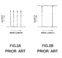
- the optical direct amplifier as shown in FIGS. 2A and 2B, if a fault occurs in two of the four channels the optical output level per channel of the remaining channels becomes higher than in normal operation. Then, the non-linear effect of the transmission line fiber disables the optical transmission.
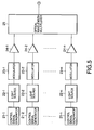
- FIG. 3 shows an example of the optical direct amplifier according to the present invention.
- the optical direct amplifier comprises an erbium doped fiber 1, the optical coupler 2, the optical isolator 3, the optical splitter 4, the excitation laser 5, the excitation laser control circuit 6, and the O/E (opto-electric) converter 7.
- the portion including these components is the same as the conventional structure shown in FIG. 1.
- the optical direct amplifier according to the present invention further comprises a frequency variable filter 8, a frequency variable filter control circuit 9, and a signal count circuit 10.
- the output from the O/E (opto-electric) converter 7 is input to the frequency variable filter 8, and the output of the frequency variable filter 8 is input to the signal count circuit 10.
- the frequency variable filter control circuit 9 is connected to the frequency variable filter 8 and the signal count circuit 10, and controls these units.
- the output (count value) of the signal count circuit 10 is input to the excitation laser control circuit 6.
- the excitation laser control circuit 6 controls the excitation laser 5 depending on the output of the signal count circuit 10.
- Each optical direct amplifier amplifies a wavelength multiplexed signal light which is propagated in an optical fiber transmission line to a predetermined level.
- the optical transmission unit 11 comprises control signal generators 21-1 through 21-n, light sources 22-1 through 22-n, modulators 23-1 through 23-n, optical direct amplifiers 24-1 through 24-n, and an optical wavelength multiplexer 25.
- Control signals having different frequencies f1 through fn are input from the control signal generators 21-1 through 21-n to the light sources 22-1 through 22-n having n different wavelengths.
- the optical output with the control signal is output from these light sources.
- the modulators 23-1 through 23-n for modulating the optical output are connected to the output units of the light sources 22-1 through 22- n respectively. These modulators 23-1 through 23-n put the data to be transmitted to the optical receiver onto the optical output from the light sources 22-1 through 22-n.
- the wavelengths of the light sources are 1.3 micron band, 1.55 micron band, etc.
- the modulated frequencies are MHz band through GHz band.
- the modulated frequency depends on the system in which the optical direct amplifier is used.
- the optical direct amplifiers 24-1 through 24-n are connected to the outputs of the modulators 23-1 through 23-n.
- the optical wavelength multiplexer 25 is connected to the outputs of the optical direct amplifiers 24-1 through 24-n.
- the n signal lights are changed into wavelength multiplexed signals in the optical wavelength multiplexer 25, and transmitted to the optical fiber transmission line 12-1.
- the optical transmission unit 11 transmits a wavelength multiplexed signal light containing n (e.g. four) signal lights modulated by the frequencies f1 through fn.
- n e.g. four
- the optical wavelength multiplexed signal light is input to an optical direct amplifier 3-i, the optical wavelength multiplexed signal light is branched by the optical splitter 4, and then converted into an electric signal by the O/E converter 7.
- the frequency variable filter 8 sweeps the electric signal output from the O/E converter 7, and detects the frequencies f1 through fn (refer to FIGS. 6A and 6B).
- the modulated frequencies detected by the frequency variable filter 8 are counted for a predetermined time by the signal count circuit 10 operating in synchronization with the frequency variable filter control circuit 9.
- the signal count circuit 10 transmits the result to the excitation laser control circuit 6.
- the excitation laser control circuit 6 controls the excitation laser 5 depending on the counted number of signal lights such that the output level per channel of the optical direct amplifier can be the initialization value. If two of the (for example) four channels are interrupted for any reason, the number of modulated frequencies counted by the signal count circuit 10 is 2.
- the excitation laser control circuit 6 controls the optical output level per channel to be +2dBm/channel which is equal to the initialization value. Relating to the output of each channel, as shown in FIGS. 7A and 7B, the optical output level per channel of the optical direct amplifier at the initialization is substantially equal to the optical output level per channel at the time when a fault occurs in two channels. When the channels increase in number, the output level per channel of the optical direct amplifier can be similarly controlled as described above.
- FIG. 8 shows another example of the configuration of the optical wavelength multiplexed transmission system.
- the optical output from each of the optical transmission units 11a and 11b is coupled by an optical coupler 15, and transmitted to one optical reception unit 14.
- the output level of the optical direct amplifier can be optimally controlled by detecting the number of multiplexed signals in the light output from the optical direct amplifier, and by controlling the output of the optical direct amplifier depending on the number of the detected signals even it the number of signals is reduced due to the occurrence of a fault, etc. or if the number of signals is increased on the transmitting side.
- An optical direct amplifier includes an O/E converter for converting a branched output light into an electric signal, a frequency variable filter for detecting a modulated frequency specific to a signal light from the electric signal, a counter for counting the number of modulated frequencies detected, and a control circuit.
- the control circuit controls the output of the optical direct amplifier such that the optical output level per signal light can be equal to the optical output level per signal light indicated before the count value (number of signal lights) changes.
Landscapes
- Physics & Mathematics (AREA)
- Electromagnetism (AREA)
- Engineering & Computer Science (AREA)
- Computer Networks & Wireless Communication (AREA)
- Signal Processing (AREA)
- Plasma & Fusion (AREA)
- Optics & Photonics (AREA)
- Optical Communication System (AREA)
- Lasers (AREA)
Abstract
Description
- The present invention relates to an optical direct amplifier and the control method thereof, and more specifically to an optical direct amplifier for amplifying a wavelength multiplexed signal light and a method for controlling its output level.
- In the conventional optical wavelength multiplexed transmission system, an optical fiber transmission line and an optical direct amplifier are alternately connected and mounted between an optical transmission unit for transmitting a wavelength multiplexed signal light and an optical reception unit. The optical direct amplifier includes a rare-earth added fiber, an optical coupler, an optical isolator, an optical splitter, an excitation laser, an excitation laser control circuit, an O/E (opto-electric) converter, etc. One end of the rare-earth added fiber is connected to an input of the optical direct amplifier, and the other is connected to the optical coupler. An
optical isolator 3 is connected to the optical coupler, and the optical splitter is connected to the output of the optical isolator. One output of the optical splitter is the output of the optical direct amplifier, and the other output is connected to the O/E converter. The excitation laser control circuit is connected to the O/E converter, and the excitation laser is connected to the excitation laser control circuit. As described in Japanese Patent Application Laid-Open No. 6-338874, etc., the excitation laser control circuit controls the output of the excitation laser such that the output level of the optical direct amplifier can be constant based on the signal converted into an electric signal by the O/E converter. - When the optical transmission unit transmits a wavelength multiplexed signal light having, for example, four wavelengths (hereinafter referred to as 4 channels) in the conventional optical wavelength multiplexed transmission system, the output level is controlled to be constant (for example, +8dBm/4 channels based on +2dBm/1 channel). However, even if two channels of the four channels are interrupted for any reason, the excitation laser control circuit controls the output level of the optical direct amplifier to be totally +8dBm. Therefore, the optical output level per channel is controlled to be +5dBm, which is higher than in a normal operation (4 channels). At this time, the transmission is disabled by the nonlinear effect of the optical fiber transmission line. On the other hand, when a signal eight is increased in number, the optical output level per channel is lower than in the normal operation (4 channels).
- The present invention aims at optically controlling the output level of an optical direct amplifier even when the number of signal lights is decreased by a fault, etc. or when the number of the signal lights is increased on the transmitting side.
- Accordingly, in a first aspect the present invention provides an optical direct amplifier which amplifies wavelength multiplexed signal lights, comprising:
- detecting means for detecting the number of multiplexed signal lights; and
- controlling means for controlling the output of said optical direct amplifier depending on the number of signal lights detected by said detecting means.
-
- In a second aspect the present invention provides a method of controlling an optical direct amplifier, comprising the steps of:
- counting the number of wavelength multiplexed signal lights; and
- controlling the optical output level per signal light depending on the number of signal lights.
-
- In a third aspect, the present invention provides an optical wavelength multiplexed transmission system, comprising:
- an optical transmission unit;
- an optical reception unit;
- an optical fibre transmission line provided between said optical transmission unit and said optical reception unit; and
- an optical direct amplifier as set forth above provided between said optical fibre transmission lines.
-
- The invention may also be defined as follows:
- The optical direct amplifier includes a detector for detecting the number of modulated frequencies specific to an output signal light; and a control circuit for controlling the output of the optical direct amplifier depending on the number of modulated frequencies detected by the detector. The detector includes an opto-electric converter for converting an output wavelength multiplexed signal light into an electric signal; a frequency detector for detecting a modulated frequency specific to each signal light from the electric signals converted by the opto-electric converter; and a counter for counting the number of modulated frequencies. When the number of modulated frequencies specific to the signal light detected by the detector has changed, the control circuit controls the optical output level of one signal light such that the optical output level can be the same as that before the number has changed. The method of controlling the optical direct amplifier includes the steps of counting the number of modulated frequencies specific to the wavelength multiplexed signal light, and controlling, if the number has changed, the optical output level per signal light to be the same as the optical output level per signal light obtained before the number has changed. The optical wavelength multiplexed transmission system includes an optical transmission unit, an optical reception unit, optical fiber transmission lines, and an optical direct amplifier provided between the optical fiber transmission lines. The optical direct amplifier includes a detector for detecting the number of modulated frequencies specific to an output signal light; and a control circuit for controlling the output of the optical direct amplifier depending on the number of modulated frequencies detected by the detector.
- The above described optical direct amplifier maintains an initialization value as the output level per channel even if the number of signal lights increases or decreases. BRIEF DESCRIPTION OF THE DRAWINGS
- Preferred features of the present invention will now be described, purely by way of example only, with reference to the accompanying drawings, in which:-
- FIG. 1 is a block diagram showing the conventional optical direct amplifier;
- FIGS. 2A and 2B show the spectra of the output of 4 channels and 2 channels of the conventional optical direct amplifier;
- FIG. 3 is a block diagram showing the optical direct amplifier according to the present invention;
- FIG. 4 is a block diagram showing the optical wavelength multiplexed transmission system;
- FIG. 5 is a block diagram of the optical transmission unit;
- FIGS. 6A and 6B are timing charts showing the counting operations;
- FIGS. 7A and 7B show the spectra of the output of the optical direct amplifier according to the present invention; and
- FIG. 8 is a block diagram showing another optical wavelength multiplexed transmission system according to the invention.
-
- In the conventional optical direct amplifier shown in FIG. 1, one end of a rare-earth added
fiber 1 is connected to an input of the optical direct amplifier, and the other end is connected to anoptical coupler 2. Anoptical isolator 3 which passes a signal in one direction only is connected to theoptical coupler 2. Anoptical splitter 4 is connected to an output unit of theoptical isolator 3. One of the output unit of theoptical splitter 4 is the output unit of the optical direct amplifier, and the other output unit is connected to an O/E converter 7. An excitationlaser control circuit 6 is connected to the output unit of the O/E converter 7. Anexcitation laser 5 is connected to the excitationlaser control circuit 6. The excitationlaser control circuit 6 controls the output of theexcitation laser 5 such that the output level of the optical direct amplifier can be constant based on the signal converted into an electric signal by the O/E converter 7. In the above described optical direct amplifier, as shown in FIGS. 2A and 2B, if a fault occurs in two of the four channels the optical output level per channel of the remaining channels becomes higher than in normal operation. Then, the non-linear effect of the transmission line fiber disables the optical transmission. - FIG. 3 shows an example of the optical direct amplifier according to the present invention. The optical direct amplifier comprises an erbium doped
fiber 1, theoptical coupler 2, theoptical isolator 3, theoptical splitter 4, theexcitation laser 5, the excitationlaser control circuit 6, and the O/E (opto-electric)converter 7. The portion including these components is the same as the conventional structure shown in FIG. 1. The optical direct amplifier according to the present invention further comprises afrequency variable filter 8, a frequency variablefilter control circuit 9, and asignal count circuit 10. The output from the O/E (opto-electric)converter 7 is input to thefrequency variable filter 8, and the output of thefrequency variable filter 8 is input to thesignal count circuit 10. The frequency variablefilter control circuit 9 is connected to thefrequency variable filter 8 and thesignal count circuit 10, and controls these units. The output (count value) of thesignal count circuit 10 is input to the excitationlaser control circuit 6. The excitationlaser control circuit 6 controls theexcitation laser 5 depending on the output of thesignal count circuit 10. - As shown in FIG. 4, the optical wavelength multiplexed transmission system comprises an
optical transmission unit 11, optical fiber transmission lines 12-1 through 12-(m+1), an optical direct amplifier 13-i (i = 1, ..., m), and anoptical reception unit 14. Each optical direct amplifier amplifies a wavelength multiplexed signal light which is propagated in an optical fiber transmission line to a predetermined level. - As shown in FIG. 5, the
optical transmission unit 11 comprises control signal generators 21-1 through 21-n, light sources 22-1 through 22-n, modulators 23-1 through 23-n, optical direct amplifiers 24-1 through 24-n, and anoptical wavelength multiplexer 25. Control signals having different frequencies f1 through fn are input from the control signal generators 21-1 through 21-n to the light sources 22-1 through 22-n having n different wavelengths. The optical output with the control signal is output from these light sources. The modulators 23-1 through 23-n for modulating the optical output are connected to the output units of the light sources 22-1 through 22- n respectively. These modulators 23-1 through 23-n put the data to be transmitted to the optical receiver onto the optical output from the light sources 22-1 through 22-n. For example, the wavelengths of the light sources are 1.3 micron band, 1.55 micron band, etc., and the modulated frequencies are MHz band through GHz band. The modulated frequency depends on the system in which the optical direct amplifier is used. The optical direct amplifiers 24-1 through 24-n are connected to the outputs of the modulators 23-1 through 23-n. Theoptical wavelength multiplexer 25 is connected to the outputs of the optical direct amplifiers 24-1 through 24-n. The n signal lights are changed into wavelength multiplexed signals in theoptical wavelength multiplexer 25, and transmitted to the optical fiber transmission line 12-1. - Described below are the operations of the optical direct amplifier according to the present invention. The
optical transmission unit 11 transmits a wavelength multiplexed signal light containing n (e.g. four) signal lights modulated by the frequencies f1 through fn. When the optical wavelength multiplexed signal light is input to an optical direct amplifier 3-i, the optical wavelength multiplexed signal light is branched by theoptical splitter 4, and then converted into an electric signal by the O/E converter 7. - Using the control signal of the frequency variable
filter control circuit 9, the frequencyvariable filter 8 sweeps the electric signal output from the O/E converter 7, and detects the frequencies f1 through fn (refer to FIGS. 6A and 6B). The modulated frequencies detected by the frequencyvariable filter 8 are counted for a predetermined time by thesignal count circuit 10 operating in synchronization with the frequency variablefilter control circuit 9. Thesignal count circuit 10 transmits the result to the excitationlaser control circuit 6. The excitationlaser control circuit 6 controls theexcitation laser 5 depending on the counted number of signal lights such that the output level per channel of the optical direct amplifier can be the initialization value. If two of the (for example) four channels are interrupted for any reason, the number of modulated frequencies counted by thesignal count circuit 10 is 2. Upon receipt of the signal count value, the excitationlaser control circuit 6 controls the optical output level per channel to be +2dBm/channel which is equal to the initialization value. Relating to the output of each channel, as shown in FIGS. 7A and 7B, the optical output level per channel of the optical direct amplifier at the initialization is substantially equal to the optical output level per channel at the time when a fault occurs in two channels. When the channels increase in number, the output level per channel of the optical direct amplifier can be similarly controlled as described above. - FIG. 8 shows another example of the configuration of the optical wavelength multiplexed transmission system. The optical output from each of the
optical transmission units optical coupler 15, and transmitted to oneoptical reception unit 14. With the configuration, the effect obtained with the configuration shown in FIG. 4 can be obtained. As described above, the output level of the optical direct amplifier can be optimally controlled by detecting the number of multiplexed signals in the light output from the optical direct amplifier, and by controlling the output of the optical direct amplifier depending on the number of the detected signals even it the number of signals is reduced due to the occurrence of a fault, etc. or if the number of signals is increased on the transmitting side. - While the present invention has been described in connection with certain preferred embodiments, it is to be understood that the subject matter encompassed by the present invention is not limited to those specific embodiments. On the contrary, it is intended to include all alternatives, modifications, and equivalents as can be included within the scope of the following claims.
- While the present invention has been described in its preferred embodiments, it is to be understood that the words which have been used are words of description rather than limitation and that changes may be made to the invention without departing from its scope as defined by the appended claims.
- Each feature disclosed in this specification (which term includes the claims) and/or shown in the drawings may be incorporated in the invention independently of other disclosed and/or illustrated features.
- Statements in this specification of the "objects of the invention" relate to preferred embodiments of the invention, but not necessarily to all embodiments of the invention falling within the claims.
- The text of the abstract filed herewith is repeated here as part of the specification.
- An optical direct amplifier includes an O/E converter for converting a branched output light into an electric signal, a frequency variable filter for detecting a modulated frequency specific to a signal light from the electric signal, a counter for counting the number of modulated frequencies detected, and a control circuit. When the count value (number of signal lights) output from the counter changes, the control circuit controls the output of the optical direct amplifier such that the optical output level per signal light can be equal to the optical output level per signal light indicated before the count value (number of signal lights) changes.
Claims (14)
- An optical direct amplifier which amplifies wavelength multiplexed signal lights, comprising:detecting means for detecting the number of multiplexed signal lights; andcontrolling means for controlling the output of said optical direct amplifier depending on the number of signal lights detected by said detecting means.
- The amplifier according to Claim 1, wherein the detecting means for detecting the number of multiplexed signal lights comprisesmeans for detecting a respective modulation frequency specific to each signal light; andmeans for counting the number of modulation frequencies.
- The amplifier according to Claim 1 or Claim 2, wherein said detecting means comprises:an opto-electric converter for converting an optical wavelength multiplexed signal light to be output into an electric signal;a frequency detector for detecting a modulated frequency specific to each signal light from the electric signal converted by said opto-electric converter; anda counter for counting the number of modulated frequencies detected by said frequency detector.
- The amplifier according to any preceding claim, wherein the controlling means is adapted to control the optical output level per signal light such that, when the number of multiplexed signal lights detected by said detecting means increases or decreases, the optical output level per signal light is the same before and after the change.
- The amplifier according to any preceding claim, wherein said detecting means comprises a frequency variable filter and a control circuit thereof.
- The amplifier according to any preceding claim, further comprising an optical splitter for branching an optical wavelength multiplexed signal light and inputting a branched light to said detecting means.
- The amplifier according to any preceding claim, further comprising:a rare-earth added fibre; anda light source for generating an excitation light to be input to said fiber.
- The amplifier according to Claim 1, wherein the detecting means comprises means for detecting the number of modulated frequencies specific to each signal light.
- A method of controlling an optical direct amplifier, comprising the steps of:counting the number of wavelength multiplexed signal lights; andcontrolling the optical output level per signal light depending on the number of signal lights.
- The method according to Claim 9, wherein the counting step comprises counting the number of modulated frequencies, each frequency being specific to a wavelength multiplexed signal light.
- The method according to Claim 10, wherein said counting step for counting the number of modulated frequencies comprises the steps of:converting the output of the optical direct amplifier into an electric signal; anddetecting the modulated frequencies contained in the electric signal.
- The method according to Claim 11, wherein said modulated frequency is detected by sweeping said electric signal using a frequency variable filter.
- The method according to any of Claims 9 to 12, wherein the controlling step comprises controlling the optical output level per signal light such that, when the number of multiplexed signal lights detected increases or decreases, the optical output level per signal light is the same before and after the change.
- An optical wavelength multiplexed transmission system, comprising:an optical transmission unit;an optical reception unit;an optical fibre transmission line provided between said optical transmission unit and said optical reception unit; andan optical direct amplifier according to any of Claims 1 to 8 provided between said optical fibre transmission lines.
Applications Claiming Priority (2)
| Application Number | Priority Date | Filing Date | Title |
|---|---|---|---|
| JP09339551A JP3102397B2 (en) | 1997-12-10 | 1997-12-10 | Optical WDM transmission system |
| JP33955197 | 1997-12-10 |
Publications (2)
| Publication Number | Publication Date |
|---|---|
| EP0923205A2 true EP0923205A2 (en) | 1999-06-16 |
| EP0923205A3 EP0923205A3 (en) | 2000-03-29 |
Family
ID=18328547
Family Applications (1)
| Application Number | Title | Priority Date | Filing Date |
|---|---|---|---|
| EP98310120A Withdrawn EP0923205A3 (en) | 1997-12-10 | 1998-12-10 | Optical direct amplifier and control method thereof |
Country Status (3)
| Country | Link |
|---|---|
| US (1) | US6449085B1 (en) |
| EP (1) | EP0923205A3 (en) |
| JP (1) | JP3102397B2 (en) |
Families Citing this family (3)
| Publication number | Priority date | Publication date | Assignee | Title |
|---|---|---|---|---|
| JP3338007B2 (en) * | 1999-09-10 | 2002-10-28 | 古河電気工業株式会社 | Optical amplifier and WDM optical communication system |
| JP3387483B2 (en) * | 2000-08-31 | 2003-03-17 | 日本電気株式会社 | Optical direct amplifier and control method thereof |
| US20040017603A1 (en) * | 2002-07-29 | 2004-01-29 | Paul Jay | Optical amplifier controller |
Citations (5)
| Publication number | Priority date | Publication date | Assignee | Title |
|---|---|---|---|---|
| GB2294170A (en) * | 1994-09-26 | 1996-04-17 | Fujitsu Ltd | Optical amplification of wavelength-division-multiplexed signals |
| EP0762569A2 (en) * | 1995-08-23 | 1997-03-12 | Fujitsu Limited | Method and apparatus for controlling optical amplifier used for optically amplifying wavelength-division multiplexed signal |
| US5680247A (en) * | 1995-06-07 | 1997-10-21 | Nec Corporation | Optical amplification monitoring apparatus |
| FR2747849A1 (en) * | 1996-04-23 | 1997-10-24 | Nec Corp | Multiple wavelength light amplifier for optical communications |
| US5699081A (en) * | 1996-09-26 | 1997-12-16 | Lucent Technologies Inc. | Apparatus and method for automatically provisioning power on a per channel basis in a communications transmission system |
Family Cites Families (15)
| Publication number | Priority date | Publication date | Assignee | Title |
|---|---|---|---|---|
| JPH0621897A (en) | 1992-07-01 | 1994-01-28 | Nippon Telegr & Teleph Corp <Ntt> | Wavelength multiplex optical amplification relay transmission system and optical amplifier repeater |
| JPH06104868A (en) | 1992-09-22 | 1994-04-15 | Nippon Telegr & Teleph Corp <Ntt> | Wavelength multiplexed optical relay transmission system |
| JP2793469B2 (en) | 1993-05-26 | 1998-09-03 | 日本電気 株式会社 | Supervisory control signal receiving method of optical direct amplifier |
| JP2871547B2 (en) * | 1995-09-08 | 1999-03-17 | 日本電気株式会社 | Optical spectrum analyzer apparatus and optical amplifier control method |
| JPH09219696A (en) | 1996-02-14 | 1997-08-19 | Nippon Telegr & Teleph Corp <Ntt> | Optical amplifier |
| JPH09219680A (en) | 1996-02-14 | 1997-08-19 | Nippon Telegr & Teleph Corp <Ntt> | Optical transmission system |
| JP2910667B2 (en) * | 1996-04-09 | 1999-06-23 | 日本電気株式会社 | Linear repeater optical amplification transmission equipment |
| JP3070482B2 (en) | 1996-07-03 | 2000-07-31 | 日本電気株式会社 | Optical transmitter and receiver for wavelength multiplexed optical transmission |
| JP2904131B2 (en) * | 1996-07-04 | 1999-06-14 | 日本電気株式会社 | WDM optical amplifier and WDM optical transmission equipment |
| JP3006500B2 (en) | 1996-08-01 | 2000-02-07 | 日本電気株式会社 | Optical amplifier for wavelength multiplexed optical transmission |
| JP2991131B2 (en) * | 1996-10-07 | 1999-12-20 | 日本電気株式会社 | Signal optical channel number counter and optical amplifier using the same |
| JPH10229386A (en) | 1997-02-17 | 1998-08-25 | Nec Corp | Optical fiber amplifier and optical communication using the same |
| JPH10242939A (en) | 1997-02-27 | 1998-09-11 | Nec Corp | Wavelength multiplex optical communication system |
| JP3068500B2 (en) * | 1997-04-25 | 2000-07-24 | 日本電気株式会社 | Optical signal amplification transmission system |
| US6163399A (en) * | 1998-12-08 | 2000-12-19 | Nortel Networks Limited | Method and apparatus for suppressing transients in optical amplifiers |
-
1997
- 1997-12-10 JP JP09339551A patent/JP3102397B2/en not_active Expired - Fee Related
-
1998
- 1998-12-10 US US09/208,412 patent/US6449085B1/en not_active Expired - Fee Related
- 1998-12-10 EP EP98310120A patent/EP0923205A3/en not_active Withdrawn
Patent Citations (5)
| Publication number | Priority date | Publication date | Assignee | Title |
|---|---|---|---|---|
| GB2294170A (en) * | 1994-09-26 | 1996-04-17 | Fujitsu Ltd | Optical amplification of wavelength-division-multiplexed signals |
| US5680247A (en) * | 1995-06-07 | 1997-10-21 | Nec Corporation | Optical amplification monitoring apparatus |
| EP0762569A2 (en) * | 1995-08-23 | 1997-03-12 | Fujitsu Limited | Method and apparatus for controlling optical amplifier used for optically amplifying wavelength-division multiplexed signal |
| FR2747849A1 (en) * | 1996-04-23 | 1997-10-24 | Nec Corp | Multiple wavelength light amplifier for optical communications |
| US5699081A (en) * | 1996-09-26 | 1997-12-16 | Lucent Technologies Inc. | Apparatus and method for automatically provisioning power on a per channel basis in a communications transmission system |
Also Published As
| Publication number | Publication date |
|---|---|
| JP3102397B2 (en) | 2000-10-23 |
| JPH11177532A (en) | 1999-07-02 |
| EP0923205A3 (en) | 2000-03-29 |
| US6449085B1 (en) | 2002-09-10 |
Similar Documents
| Publication | Publication Date | Title |
|---|---|---|
| EP1248392B1 (en) | Optical amplifier device and bidirectional wavelength division multiplexing optical communication system using the same | |
| JP2991131B2 (en) | Signal optical channel number counter and optical amplifier using the same | |
| JP2809132B2 (en) | Optical amplification monitoring device | |
| EP1298764B1 (en) | Device and method for optical amplification | |
| JPH09289503A (en) | Optical amplification device and wavelength multiplex optical transmission device using same | |
| US5323474A (en) | Lossless optical signal splitter including remotely pumped amplifier | |
| EP1081880B1 (en) | Wdm transmission repeater, wdm transmission system and wdm transmission method | |
| JP2904131B2 (en) | WDM optical amplifier and WDM optical transmission equipment | |
| JP2914334B2 (en) | Optical amplifier output level control method for WDM communication system | |
| US6025948A (en) | Optical signal transmission installation including a repeater monitoring system | |
| CA2268005C (en) | Wavelength division multiplexed signal amplifier | |
| EP0923205A2 (en) | Optical direct amplifier and control method thereof | |
| US6211981B1 (en) | Optical wavelength multiplex transmission system using repeaters | |
| JP2720777B2 (en) | WDM optical communication system | |
| EP1503528B1 (en) | Optical amplifier and optical communication system | |
| EP1376905B1 (en) | Optical transmission system with Raman amplification | |
| EP0862291A2 (en) | Wavelength division multiplexing communication system | |
| US6907157B2 (en) | Method and system for optical fiber transmission using raman amplification | |
| JP2000077757A (en) | Optical amplifier, optical transmission device and system thereof | |
| JPH01130638A (en) | Frequency multiplex optical two-way transmitter | |
| JPH11266203A (en) | Optical receiver, wavelength multiple optical receiver, time division multiple optical receiver and optical transmission system using them | |
| JPH11331095A (en) | Wide band optical signal transmission system | |
| JPH11266204A (en) | Optical receiver, wavelength multiple optical receiver, time division multiple optical receiver and optical transmission system using them | |
| JP2002164848A (en) | Optical wavelength multiplexing transmission system |
Legal Events
| Date | Code | Title | Description |
|---|---|---|---|
| PUAI | Public reference made under article 153(3) epc to a published international application that has entered the european phase |
Free format text: ORIGINAL CODE: 0009012 |
|
| AK | Designated contracting states |
Kind code of ref document: A2 Designated state(s): FR GB |
|
| AX | Request for extension of the european patent |
Free format text: AL;LT;LV;MK;RO;SI |
|
| PUAL | Search report despatched |
Free format text: ORIGINAL CODE: 0009013 |
|
| AK | Designated contracting states |
Kind code of ref document: A3 Designated state(s): AT BE CH CY DE DK ES FI FR GB GR IE IT LI LU MC NL PT SE |
|
| AX | Request for extension of the european patent |
Free format text: AL;LT;LV;MK;RO;SI |
|
| RIC1 | Information provided on ipc code assigned before grant |
Free format text: 7H 04J 14/02 A, 7H 04B 10/145 B, 7H 04B 10/16 B, 7H 04B 10/08 B, 7H 04B 10/17 B |
|
| 17P | Request for examination filed |
Effective date: 20000302 |
|
| AKX | Designation fees paid |
Free format text: FR GB |
|
| REG | Reference to a national code |
Ref country code: DE Ref legal event code: 8566 |
|
| STAA | Information on the status of an ep patent application or granted ep patent |
Free format text: STATUS: THE APPLICATION HAS BEEN WITHDRAWN |
|
| 18W | Application withdrawn |
Effective date: 20030711 |