EP0922914A2 - Optical system for utlizing solar energy - Google Patents
Optical system for utlizing solar energy Download PDFInfo
- Publication number
- EP0922914A2 EP0922914A2 EP98830742A EP98830742A EP0922914A2 EP 0922914 A2 EP0922914 A2 EP 0922914A2 EP 98830742 A EP98830742 A EP 98830742A EP 98830742 A EP98830742 A EP 98830742A EP 0922914 A2 EP0922914 A2 EP 0922914A2
- Authority
- EP
- European Patent Office
- Prior art keywords
- solar energy
- optical fiber
- collector
- energy
- optical
- Prior art date
- Legal status (The legal status is an assumption and is not a legal conclusion. Google has not performed a legal analysis and makes no representation as to the accuracy of the status listed.)
- Withdrawn
Links
- 230000003287 optical effect Effects 0.000 title claims abstract description 23
- 239000013307 optical fiber Substances 0.000 claims abstract description 34
- 230000005855 radiation Effects 0.000 claims abstract description 10
- 239000012530 fluid Substances 0.000 claims description 5
- 230000033001 locomotion Effects 0.000 claims description 4
- 239000011159 matrix material Substances 0.000 claims 1
- 239000000835 fiber Substances 0.000 description 11
- XLYOFNOQVPJJNP-UHFFFAOYSA-N water Substances O XLYOFNOQVPJJNP-UHFFFAOYSA-N 0.000 description 8
- 238000010438 heat treatment Methods 0.000 description 6
- 238000009434 installation Methods 0.000 description 6
- 239000012141 concentrate Substances 0.000 description 3
- 230000001932 seasonal effect Effects 0.000 description 3
- 238000001228 spectrum Methods 0.000 description 3
- VYPSYNLAJGMNEJ-UHFFFAOYSA-N Silicium dioxide Chemical compound O=[Si]=O VYPSYNLAJGMNEJ-UHFFFAOYSA-N 0.000 description 2
- 238000010521 absorption reaction Methods 0.000 description 2
- 230000005540 biological transmission Effects 0.000 description 2
- 238000006243 chemical reaction Methods 0.000 description 2
- 238000010411 cooking Methods 0.000 description 2
- 239000002184 metal Substances 0.000 description 2
- 230000002745 absorbent Effects 0.000 description 1
- 239000002250 absorbent Substances 0.000 description 1
- 238000001035 drying Methods 0.000 description 1
- 230000000694 effects Effects 0.000 description 1
- 125000002887 hydroxy group Chemical group [H]O* 0.000 description 1
- 238000005286 illumination Methods 0.000 description 1
- 239000012535 impurity Substances 0.000 description 1
- 238000005259 measurement Methods 0.000 description 1
- 230000009347 mechanical transmission Effects 0.000 description 1
- 238000000034 method Methods 0.000 description 1
- 229920000515 polycarbonate Polymers 0.000 description 1
- 239000004417 polycarbonate Substances 0.000 description 1
- 238000005057 refrigeration Methods 0.000 description 1
- 239000000377 silicon dioxide Substances 0.000 description 1
- 230000009182 swimming Effects 0.000 description 1
Images

Classifications
-
- F—MECHANICAL ENGINEERING; LIGHTING; HEATING; WEAPONS; BLASTING
- F21—LIGHTING
- F21S—NON-PORTABLE LIGHTING DEVICES; SYSTEMS THEREOF; VEHICLE LIGHTING DEVICES SPECIALLY ADAPTED FOR VEHICLE EXTERIORS
- F21S11/00—Non-electric lighting devices or systems using daylight
-
- F—MECHANICAL ENGINEERING; LIGHTING; HEATING; WEAPONS; BLASTING
- F24—HEATING; RANGES; VENTILATING
- F24S—SOLAR HEAT COLLECTORS; SOLAR HEAT SYSTEMS
- F24S23/00—Arrangements for concentrating solar-rays for solar heat collectors
- F24S23/12—Light guides
-
- F—MECHANICAL ENGINEERING; LIGHTING; HEATING; WEAPONS; BLASTING
- F24—HEATING; RANGES; VENTILATING
- F24S—SOLAR HEAT COLLECTORS; SOLAR HEAT SYSTEMS
- F24S23/00—Arrangements for concentrating solar-rays for solar heat collectors
- F24S23/30—Arrangements for concentrating solar-rays for solar heat collectors with lenses
- F24S23/31—Arrangements for concentrating solar-rays for solar heat collectors with lenses having discontinuous faces, e.g. Fresnel lenses
-
- F—MECHANICAL ENGINEERING; LIGHTING; HEATING; WEAPONS; BLASTING
- F24—HEATING; RANGES; VENTILATING
- F24S—SOLAR HEAT COLLECTORS; SOLAR HEAT SYSTEMS
- F24S30/00—Arrangements for moving or orienting solar heat collector modules
- F24S30/40—Arrangements for moving or orienting solar heat collector modules for rotary movement
- F24S30/45—Arrangements for moving or orienting solar heat collector modules for rotary movement with two rotation axes
- F24S30/455—Horizontal primary axis
-
- G—PHYSICS
- G02—OPTICS
- G02B—OPTICAL ELEMENTS, SYSTEMS OR APPARATUS
- G02B6/00—Light guides; Structural details of arrangements comprising light guides and other optical elements, e.g. couplings
- G02B6/0001—Light guides; Structural details of arrangements comprising light guides and other optical elements, e.g. couplings specially adapted for lighting devices or systems
- G02B6/0005—Light guides; Structural details of arrangements comprising light guides and other optical elements, e.g. couplings specially adapted for lighting devices or systems the light guides being of the fibre type
- G02B6/0008—Light guides; Structural details of arrangements comprising light guides and other optical elements, e.g. couplings specially adapted for lighting devices or systems the light guides being of the fibre type the light being emitted at the end of the fibre
-
- H—ELECTRICITY
- H01—ELECTRIC ELEMENTS
- H01L—SEMICONDUCTOR DEVICES NOT COVERED BY CLASS H10
- H01L31/00—Semiconductor devices sensitive to infrared radiation, light, electromagnetic radiation of shorter wavelength or corpuscular radiation and specially adapted either for the conversion of the energy of such radiation into electrical energy or for the control of electrical energy by such radiation; Processes or apparatus specially adapted for the manufacture or treatment thereof or of parts thereof; Details thereof
- H01L31/04—Semiconductor devices sensitive to infrared radiation, light, electromagnetic radiation of shorter wavelength or corpuscular radiation and specially adapted either for the conversion of the energy of such radiation into electrical energy or for the control of electrical energy by such radiation; Processes or apparatus specially adapted for the manufacture or treatment thereof or of parts thereof; Details thereof adapted as photovoltaic [PV] conversion devices
- H01L31/054—Optical elements directly associated or integrated with the PV cell, e.g. light-reflecting means or light-concentrating means
- H01L31/0543—Optical elements directly associated or integrated with the PV cell, e.g. light-reflecting means or light-concentrating means comprising light concentrating means of the refractive type, e.g. lenses
-
- H—ELECTRICITY
- H01—ELECTRIC ELEMENTS
- H01L—SEMICONDUCTOR DEVICES NOT COVERED BY CLASS H10
- H01L31/00—Semiconductor devices sensitive to infrared radiation, light, electromagnetic radiation of shorter wavelength or corpuscular radiation and specially adapted either for the conversion of the energy of such radiation into electrical energy or for the control of electrical energy by such radiation; Processes or apparatus specially adapted for the manufacture or treatment thereof or of parts thereof; Details thereof
- H01L31/04—Semiconductor devices sensitive to infrared radiation, light, electromagnetic radiation of shorter wavelength or corpuscular radiation and specially adapted either for the conversion of the energy of such radiation into electrical energy or for the control of electrical energy by such radiation; Processes or apparatus specially adapted for the manufacture or treatment thereof or of parts thereof; Details thereof adapted as photovoltaic [PV] conversion devices
- H01L31/054—Optical elements directly associated or integrated with the PV cell, e.g. light-reflecting means or light-concentrating means
- H01L31/0547—Optical elements directly associated or integrated with the PV cell, e.g. light-reflecting means or light-concentrating means comprising light concentrating means of the reflecting type, e.g. parabolic mirrors, concentrators using total internal reflection
-
- F—MECHANICAL ENGINEERING; LIGHTING; HEATING; WEAPONS; BLASTING
- F24—HEATING; RANGES; VENTILATING
- F24S—SOLAR HEAT COLLECTORS; SOLAR HEAT SYSTEMS
- F24S23/00—Arrangements for concentrating solar-rays for solar heat collectors
- F24S23/70—Arrangements for concentrating solar-rays for solar heat collectors with reflectors
- F24S2023/87—Reflectors layout
-
- Y—GENERAL TAGGING OF NEW TECHNOLOGICAL DEVELOPMENTS; GENERAL TAGGING OF CROSS-SECTIONAL TECHNOLOGIES SPANNING OVER SEVERAL SECTIONS OF THE IPC; TECHNICAL SUBJECTS COVERED BY FORMER USPC CROSS-REFERENCE ART COLLECTIONS [XRACs] AND DIGESTS
- Y02—TECHNOLOGIES OR APPLICATIONS FOR MITIGATION OR ADAPTATION AGAINST CLIMATE CHANGE
- Y02E—REDUCTION OF GREENHOUSE GAS [GHG] EMISSIONS, RELATED TO ENERGY GENERATION, TRANSMISSION OR DISTRIBUTION
- Y02E10/00—Energy generation through renewable energy sources
- Y02E10/40—Solar thermal energy, e.g. solar towers
- Y02E10/47—Mountings or tracking
-
- Y—GENERAL TAGGING OF NEW TECHNOLOGICAL DEVELOPMENTS; GENERAL TAGGING OF CROSS-SECTIONAL TECHNOLOGIES SPANNING OVER SEVERAL SECTIONS OF THE IPC; TECHNICAL SUBJECTS COVERED BY FORMER USPC CROSS-REFERENCE ART COLLECTIONS [XRACs] AND DIGESTS
- Y02—TECHNOLOGIES OR APPLICATIONS FOR MITIGATION OR ADAPTATION AGAINST CLIMATE CHANGE
- Y02E—REDUCTION OF GREENHOUSE GAS [GHG] EMISSIONS, RELATED TO ENERGY GENERATION, TRANSMISSION OR DISTRIBUTION
- Y02E10/00—Energy generation through renewable energy sources
- Y02E10/50—Photovoltaic [PV] energy
- Y02E10/52—PV systems with concentrators
Definitions
- the systems for collecting and using solar energy known at the present time are essentially based on two different systems, namely the use of photovoltaic panels and water-heating collectors.
- the energy radiated by the sun is applied, directly or through an optical system, to solar cells which convert it directly into electrical energy, with the principal advantage of simple transport of the energy over a distance, but with low efficiency and poor utilization of the whole solar spectrum; moreover, these solar cells are expensive and have a limited life.
- the solar cells available at the present time have an efficiency of approximately 15% with respect to the solar energy radiated onto them, and furthermore their disposal, when they are spent, is extremely difficult.
- the solar cells are exposed directly to an unfavorable external environment.
- Water-heating collector systems have a collector surface on which the solar radiation falls directly and which, becoming hot, transfers the heat by an exchange process to a fluid which is subsequently used for the storage and transport of the thermal energy. They have a high efficiency, due to the direct energy conversion, and relatively low cost, but the system of tubes for the circulation of the fluid, normally water, is expensive and difficult to install, and entails heat losses which limit the distance of the places of use from the collector. The circulation of the water in the installation also requires the use of pumps and energy.
- This type of collector is used principally for producing hot water for sanitary purposes and, to a lesser extent, for heating buildings and swimming pools, for drying (in agriculture), and less frequently for thermal cycles, for example for refrigeration. Recent design and engineering improvements have made it possible to achieve conversion efficiencies of approximately 40%, reduced to approximately 30% by the heat losses. Moreover, the irradiated surface is subjected to the external temperature, which has an effect on the efficiency of the collector.
- the primary object of the present invention is to eliminate or substantially reduce the disadvantages of the systems described above, particularly by using a system of transporting and switching the energy toward the places of use which is highly efficient and for which the purchase and installation costs are relatively low.
- the invention proposes a system for collecting and using solar energy, comprising at least one optical concentrator provided with means of orientation, to keep a constant orientation of the concentrator toward the sun, and means of transfer and distribution which comprise a light guide or flexible optical fiber cable for transferring the solar radiation from the focus of at least one of said concentrators directly to said user devices.
- the solar energy is carried without being converted and with minimal losses directly to the point of use, at which point it is either used in its existing state as light and radiant thermal energy or is converted into predominantly thermal or electrical energy.
- the efficiency of the collection does not depend on the temperature of the external environment, and may reach values of the order of 70%, depending on the type of application.
- the possibility of carrying solar energy through said flexible optical fiber cable directly to a multiplicity of points of use such as water heaters, ovens, greenhouses, very high-efficiency concentrated photovoltaic generators, installations for health purposes and skin treatment, installations for industrial use of high-intensity light, illumination of rooms with light having the solar frequency spectrum, etc.
- a multiplicity of points of use such as water heaters, ovens, greenhouses, very high-efficiency concentrated photovoltaic generators, installations for health purposes and skin treatment, installations for industrial use of high-intensity light, illumination of rooms with light having the solar frequency spectrum, etc.
- the optical concentrator also makes it possible to provide energy at a relatively high temperature, permitting uses, such as cooking food, which could otherwise not be envisaged with the hot-water collectors.
- the collector comprises a plurality of modular elements, each comprising an optical concentrator
- the optical fiber distribution system comprises at least one adding device having a multiplicity of inputs and a single output.
- Each input is capable of receiving through an optical fiber solar energy from the focus of each modular element of the collector.
- the adding device can be used to add the amounts of energy received from the various modular elements of the collector, so that they can be sent along a single optical fiber through said output toward the user.
- the system may also comprise at least one switching device having an input connected to the output of the adding device by an optical fiber, to receive the collected solar energy, and a multiplicity of outputs, each of which is capable of sending light energy to a corresponding user device through a corresponding optical fiber.
- said concentrator may comprise an optical refracting system and/or a minor system.
- Said optical refracting system may comprise a Fresnel lens with spherical segments exposed directly to the solar radiation and concentrating the radiant flow received on one end of an optical fiber.
- Means of orientating the collector are provided, and may comprise a gimbal mounting of the collector, of each line of modular elements or of each modular element of the collector, and means controlled by an aiming system to follow the apparent motion of the sun and always expose the surface of the modular elements orthogonally to the sun.
- the optical refracting system may comprise a first Fresnel lens with parallel cylindrical segments and a second Fresnel lens extending in a dimension parallel to the axis of the cylindrical segments of said first lens; the optical axes of said two lenses are orthogonal to each other, and a mirror is interposed between said lenses to direct the solar flow from the first to the second lens, the flow being finally concentrated at the end of an optical fiber.
- the mirror is rotatable about an axis parallel to the axis of said cylindrical elements to follow the movements of the sun orthogonal to the mirror's axis of rotation, for example in order to compensate for the seasonal variations of the apparent path of the sun.
- the concentrator thus has a limited axial dimension, and requires, for orientation, the possibility of rotating the axis of each modular element solely about an axis parallel to the Earth's axis, to compensate for the apparent hourly movements of the sun.
- a further embodiment of the invention provides for the use of a mirror which can be orientated in two axes, and is interposed between the optical system and the transport system.
- the term "optical fiber” denotes either a single fiber or a bundle of optical fibers.
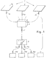
- the system comprises a collector 1 formed by a plurality of modular elements 1A; these elements may be brought together in various ways.
- Each modular element presents a square surface with a side measurement of 30 cm to the solar radiation, and can therefore collect, at southern European latitudes, up to 90 W of solar energy. It will be clear from the following description of the configuration of said modular elements that the solar energy collected by each element at the output of the element is directed by means of a corresponding optical fiber 3A, 3B, 3C, etc. into an adding device 5 on which the optical fibers of all the elements of the collector 1 converge.
- the solar energy collected by the various modular elements is directed from the adding device 5, which is conveniently located near the collector 1, through a single output optical fiber 7 to a switching device 9, from which it can be sent by means of corresponding optical fibers 11A, 11B, 11C, etc. to one or more user devices 13A, 13B, 13C, etc.
- the user devices may use the energy in the form in which it is received, for example for lighting or radiant heating, or may convert it into another form, for example into electrical or thermal energy, possibly for transmission to remote users.
- the optical fibers are of the type having low absorption losses over a wide range of frequencies of the solar spectrum, for example fibers made from silica with a low content of impurities - for good transmission in the infrared - which may be enriched with hydroxyl groups, OH, for low absorption in the ultraviolet range.
- the fibers will also be of the type with a high numerical aperture (NA), in other words of the type which accepts at the input rays with a large angle of incidence, for example 30°, or preferably 40°, thus making it possible to reduce the focal length and the overall dimensions of the optical concentrator.
- NA numerical aperture
- optical fibers running from the individual elements of the collector are physically and optically connected, at their ends furthest from said elements, to an adding device 5 which enables the solar radiation transmitted by each fiber 3A, 3B, 3C to be transferred to a single optical fiber 7 which runs from the device.
- This single fiber 7 terminates in a switching device 9 after having passed through the building, from the adding device which is preferably located near the collector (and therefore usually on the roof of the building) to a switching station within the building.
- the switch 9 comprises means capable of switching the path of the solar energy captured by the collector, and arriving through the fiber 7, between one or more fibers 11A, 11B, 11C, etc. running from the switch, each of these fibers being connected to a different user device 13A, 13B, 13C, etc.
- Said user devices may be:
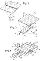
- the solar collector 1 is formed by a multiplicity of modular elements 1A in which the surface directly illuminated by the sun is the flat surface 27A (Fig. 2) of a Fresnel lens 27 with toric elements, said surface being orientated toward the sun.
- the lens 27 concentrates the received solar energy on the larger base of an optical body 28 in the form of a truncated pyramid fitted to one end of an optical fiber 3A in such a way that it directs into it the solar radiation collected by the lens 27.
- each modular element the surface directly illuminated by the sun is the flat surface 29A (Fig. 3) of a Fresnel lens 29 with cylindrical elements, said surface being orientated toward the sun.
- the Fresnel lenses 27, 31 have optical axes orthogonal to each other and a mirror 33 is interposed between them to direct the solar energy flow from the first to the second lens.
- said modular elements may be joined like tiles to form a panel 35 (Figs. 4, 5) extending in a plane or a panel 45 (Fig. 6) extending in a single line of tiles.
- Means of automatic orientation of the panel comprise an optical aiming device of the photocell type and a control unit, these not being shown in the drawing, the control unit being capable of orientating the collector by means of servo motors 37, 39 (Fig. 4) in two axes X-X, Y-Y which are orthogonal to each other. This may be achieved either by using a true gimbal mounting 36, 38, 40 of the collector (Fig. 4), or one in which (Fig.
- the collector 45 (Fig. 6) comprises a cradle support 50 for a line of modular elements 1A located next to each other; the support 50 can be rotated by means of pins 44 hinged to a fixed support 46 and defining an axis X-X.
- Each modular element 1A of the collector is hinged, by corresponding pins 48 defining an axis Y-Y orthogonal to said axis X-X of rotation of the collector, to the cradle support 50, and can be rotated by means of a mechanical transmission and a servo motor.
- the mirror 33 may be hinged with respect to the support of the lenses 29, 31, and orientated by means of said control unit and a servo motor to keep the solar energy flow leaving the lens 29 concentrated on the lens 31, thus compensating for said seasonal variation of the apparent path of the sun.
Abstract
Description
- The systems for collecting and using solar energy known at the present time are essentially based on two different systems, namely the use of photovoltaic panels and water-heating collectors.
- In photovoltaic panel systems, the energy radiated by the sun is applied, directly or through an optical system, to solar cells which convert it directly into electrical energy, with the principal advantage of simple transport of the energy over a distance, but with low efficiency and poor utilization of the whole solar spectrum; moreover, these solar cells are expensive and have a limited life. The solar cells available at the present time have an efficiency of approximately 15% with respect to the solar energy radiated onto them, and furthermore their disposal, when they are spent, is extremely difficult. Moreover, in space applications, the solar cells are exposed directly to an unfavorable external environment.
- Water-heating collector systems have a collector surface on which the solar radiation falls directly and which, becoming hot, transfers the heat by an exchange process to a fluid which is subsequently used for the storage and transport of the thermal energy. They have a high efficiency, due to the direct energy conversion, and relatively low cost, but the system of tubes for the circulation of the fluid, normally water, is expensive and difficult to install, and entails heat losses which limit the distance of the places of use from the collector. The circulation of the water in the installation also requires the use of pumps and energy. This type of collector is used principally for producing hot water for sanitary purposes and, to a lesser extent, for heating buildings and swimming pools, for drying (in agriculture), and less frequently for thermal cycles, for example for refrigeration. Recent design and engineering improvements have made it possible to achieve conversion efficiencies of approximately 40%, reduced to approximately 30% by the heat losses. Moreover, the irradiated surface is subjected to the external temperature, which has an effect on the efficiency of the collector.
- Normally, not all the energy collected is used instantly, since both the requirements of the user and the collection of energy generally vary with time in an unrelated way. Use is therefore made of thermally insulated reservoirs, but these are expensive, and can only limit, rather than eliminate, the heat losses.
- The primary object of the present invention is to eliminate or substantially reduce the disadvantages of the systems described above, particularly by using a system of transporting and switching the energy toward the places of use which is highly efficient and for which the purchase and installation costs are relatively low. This and other objects of the invention will be made clear by the following description.
- The invention proposes a system for collecting and using solar energy, comprising at least one optical concentrator provided with means of orientation, to keep a constant orientation of the concentrator toward the sun, and means of transfer and distribution which comprise a light guide or flexible optical fiber cable for transferring the solar radiation from the focus of at least one of said concentrators directly to said user devices. In this way, the solar energy is carried without being converted and with minimal losses directly to the point of use, at which point it is either used in its existing state as light and radiant thermal energy or is converted into predominantly thermal or electrical energy. Thus the efficiency of the collection does not depend on the temperature of the external environment, and may reach values of the order of 70%, depending on the type of application.
- Furthermore, the possibility of carrying solar energy through said flexible optical fiber cable directly to a multiplicity of points of use, such as water heaters, ovens, greenhouses, very high-efficiency concentrated photovoltaic generators, installations for health purposes and skin treatment, installations for industrial use of high-intensity light, illumination of rooms with light having the solar frequency spectrum, etc., permits a use of the energy which is more uniformly distributed over time, with less need to create heat reservoirs, providing savings in the costs of installation and energy losses. The optical concentrator also makes it possible to provide energy at a relatively high temperature, permitting uses, such as cooking food, which could otherwise not be envisaged with the hot-water collectors.
- In a preferred embodiment of the invention, the collector comprises a plurality of modular elements, each comprising an optical concentrator, and the optical fiber distribution system comprises at least one adding device having a multiplicity of inputs and a single output. Each input is capable of receiving through an optical fiber solar energy from the focus of each modular element of the collector. In this way the adding device can be used to add the amounts of energy received from the various modular elements of the collector, so that they can be sent along a single optical fiber through said output toward the user.
- The system may also comprise at least one switching device having an input connected to the output of the adding device by an optical fiber, to receive the collected solar energy, and a multiplicity of outputs, each of which is capable of sending light energy to a corresponding user device through a corresponding optical fiber. By changing the setting of the switch, it is possible to direct the solar energy to one or more outputs, thus enabling the energy use to be distributed according to necessity and availability.
- In a first embodiment of the invention, said concentrator may comprise an optical refracting system and/or a minor system. Said optical refracting system may comprise a Fresnel lens with spherical segments exposed directly to the solar radiation and concentrating the radiant flow received on one end of an optical fiber.
- Means of orientating the collector are provided, and may comprise a gimbal mounting of the collector, of each line of modular elements or of each modular element of the collector, and means controlled by an aiming system to follow the apparent motion of the sun and always expose the surface of the modular elements orthogonally to the sun.
- In another embodiment of the invention, the optical refracting system may comprise a first Fresnel lens with parallel cylindrical segments and a second Fresnel lens extending in a dimension parallel to the axis of the cylindrical segments of said first lens; the optical axes of said two lenses are orthogonal to each other, and a mirror is interposed between said lenses to direct the solar flow from the first to the second lens, the flow being finally concentrated at the end of an optical fiber. The mirror is rotatable about an axis parallel to the axis of said cylindrical elements to follow the movements of the sun orthogonal to the mirror's axis of rotation, for example in order to compensate for the seasonal variations of the apparent path of the sun. The concentrator thus has a limited axial dimension, and requires, for orientation, the possibility of rotating the axis of each modular element solely about an axis parallel to the Earth's axis, to compensate for the apparent hourly movements of the sun.
- A further embodiment of the invention provides for the use of a mirror which can be orientated in two axes, and is interposed between the optical system and the transport system.
- Further advantageous characteristics and embodiments of the system according to the invention are specified in the attached claims.
- The invention will be more clearly understood from the description and the attached drawing, which shows a non-restrictive practical embodiment of the invention. In the drawing,
- Fig. 1 is a schematic view of an installation for collecting and utilizing solar energy according to the invention;
- Figs. 2 and 3 are schematic perspective views of the optical system of a collector according to two embodiments of the invention;
- Figs. 4, 5 and 6 are schematic perspective views of three different embodiments of collectors according to the invention; and
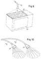
- Figs. 7, 8, 9 and 10 are schematic perspective views of appliances using the energy collected by a system according to the invention.
-
- In the remainder of this document, the term "optical fiber" denotes either a single fiber or a bundle of optical fibers. With reference to Fig. 1, the system comprises a collector 1 formed by a plurality of
modular elements 1A; these elements may be brought together in various ways. Each modular element presents a square surface with a side measurement of 30 cm to the solar radiation, and can therefore collect, at southern European latitudes, up to 90 W of solar energy. It will be clear from the following description of the configuration of said modular elements that the solar energy collected by each element at the output of the element is directed by means of a correspondingoptical fiber 3A, 3B, 3C, etc. into an addingdevice 5 on which the optical fibers of all the elements of the collector 1 converge. The solar energy collected by the various modular elements is directed from the addingdevice 5, which is conveniently located near the collector 1, through a single output optical fiber 7 to aswitching device 9, from which it can be sent by means of correspondingoptical fibers more user devices - In the described system, the optical fibers are of the type having low absorption losses over a wide range of frequencies of the solar spectrum, for example fibers made from silica with a low content of impurities - for good transmission in the infrared - which may be enriched with hydroxyl groups, OH, for low absorption in the ultraviolet range. Preferably, the fibers will also be of the type with a high numerical aperture (NA), in other words of the type which accepts at the input rays with a large angle of incidence, for example 30°, or preferably 40°, thus making it possible to reduce the focal length and the overall dimensions of the optical concentrator.
- The optical fibers running from the individual elements of the collector are physically and optically connected, at their ends furthest from said elements, to an adding
device 5 which enables the solar radiation transmitted by eachfiber 3A, 3B, 3C to be transferred to a single optical fiber 7 which runs from the device. - This single fiber 7 terminates in a
switching device 9 after having passed through the building, from the adding device which is preferably located near the collector (and therefore usually on the roof of the building) to a switching station within the building. Theswitch 9 comprises means capable of switching the path of the solar energy captured by the collector, and arriving through the fiber 7, between one ormore fibers different user device - Said user devices may be:
- a water heater (Fig. 7), comprising a
metal body 15 having acavity 16 whose surface is treated to make it absorbent. Afiber 11A is inserted in a hole of thebody 15 and opens into said cavity; in this way, thecavity 16 receives radiant solar energy which heats themetal body 15. Thebody 15 is immersed in atank 17 full of water and converts the radiant solar energy received, transferring it to the water in the form of thermal energy; - a generator of electrical energy (Fig. 8), in which
photovoltaic cells 19 are arranged facing each other on thesurface 21 of a cavity, with afiber 11B directing radiant solar energy into said cavity; - a chamber 22 (Fig. 9) which, depending on its size, may act as a
greenhouse or as an oven for heating objects or for cooking food, the top
of the chamber consisting of a Fresnel
lens 23. The end of afiber 11C, capable of projecting onto the lens the solar energy received from a collector as described above, is located above the lens at its focus. In this case, the lens acts as a diffuser for illuminating and/or heating the chamber in a uniform way; - light-dispersing lighting appliances 25 (Fig. 10), each being connected
mechanically and optically to the end of a corresponding
optical fiber 11D, 11E running from saidswitch 9, to disperse solar energy in front of it. These appliances could consist of tubular polycarbonate modules with minor-smooth internal surfaces and external surfaces having a microstructure in the form of regular prisms, for example the modules called "Linea di luce" marketed by the 3M-Italia company. With these modules it is a simple matter to construct a linear lighting system whose length is variable in a modular way. - In a first embodiment of the invention, the solar collector 1 is formed by a multiplicity of
modular elements 1A in which the surface directly illuminated by the sun is theflat surface 27A (Fig. 2) of a Fresnellens 27 with toric elements, said surface being orientated toward the sun. Thelens 27 concentrates the received solar energy on the larger base of anoptical body 28 in the form of a truncated pyramid fitted to one end of anoptical fiber 3A in such a way that it directs into it the solar radiation collected by thelens 27. - In another embodiment of the invention, in each modular element the surface directly illuminated by the sun is the
flat surface 29A (Fig. 3) of a Fresnellens 29 with cylindrical elements, said surface being orientated toward the sun. Thelens 27, with the interposition of arectangular mirror 33, concentrates the solar energy received by the lens on theflat side 31A of a second Fresnellens 31, saidsecond lens 31 extending essentially in a direction parallel to the axis of the cylindrical elements of thefirst lens 27 to concentrate the received solar energy on the larger base of anoptical body 28 in the form of a truncated pyramid fitted to one end of anoptical fiber 3A in such a way that it directs into it the solar radiation collected by thelens 29. The Fresnellenses mirror 33 is interposed between them to direct the solar energy flow from the first to the second lens. - In the solar collector, said modular elements may be joined like tiles to form a panel 35 (Figs. 4, 5) extending in a plane or a panel 45 (Fig. 6) extending in a single line of tiles.
- Means of automatic orientation of the panel are provided and comprise an optical aiming device of the photocell type and a control unit, these not being shown in the drawing, the control unit being capable of orientating the collector by means of
servo motors 37, 39 (Fig. 4) in two axes X-X, Y-Y which are orthogonal to each other. This may be achieved either by using a true gimbal mounting 36, 38, 40 of the collector (Fig. 4), or one in which (Fig. 5) one of the rotations, for example that used to follow the seasonal variations of the plane of the ecliptic, is obtained by moving one of the hinging points ofpins 42 defining an axis X-X along aslot 41 of thesupport 43 of the collector, the other hinging point being a ball joint 43. Alternatively, the collector 45 (Fig. 6) comprises acradle support 50 for a line ofmodular elements 1A located next to each other; thesupport 50 can be rotated by means ofpins 44 hinged to a fixedsupport 46 and defining an axis X-X. Eachmodular element 1A of the collector is hinged, by correspondingpins 48 defining an axis Y-Y orthogonal to said axis X-X of rotation of the collector, to thecradle support 50, and can be rotated by means of a mechanical transmission and a servo motor. Alternatively, in the case of amodular element 1A shaped as shown in Fig. 3, themirror 33 may be hinged with respect to the support of thelenses lens 29 concentrated on thelens 31, thus compensating for said seasonal variation of the apparent path of the sun. - It is to be understood that the drawing shows only an example provided solely as a practical demonstration of the invention, and that this invention may be varied in its forms and dispositions without departure from the guiding concept of the invention. The presence of any reference numbers in the attached claims has the purpose of facilitating the reading of the claims with reference to the description and to the drawing, and does not limit the scope of protection represented by the claims.
Claims (16)
- A system for collecting, transporting and utilizing solar radiation, comprising a collector which collects the solar energy radiated on to it, and means of transferring and distributing the collected energy to one or more user devices which may be relatively distant from each other, characterized in that said collector comprises at least one optical concentrator (27; 29, 31) and means of orientation (37, 39) for keeping a constant orientation of the optical concentrator toward the sun, and in that said transfer and distribution means comprise an optical fiber solar energy distribution system (3A, 3B, 3C, 7, 11A, 11B, 11C) for transferring the energy from the focus of said at least one concentrator directly to said user devices.
- The system as claimed in claim 1, characterized in that said collector comprises a plurality of modular elements (1A), each comprising an optical concentrator (27; 29, 31).
- The system as claimed in claim 2, characterized in that the optical fiber distribution system (3A, 3B, 3C, 7, 11A, 11B, 11C) comprises at least one adding device (5) having a multiplicity of inputs and one output, each input being capable of receiving through an optical fiber (3A, 3B, 3C) solar energy from the focus of each modular element (1A) of the collector, the adding device enabling the amounts of energy received from the various inputs to be added together so that they can be sent toward the user along an optical fiber (7) through said output.
- The system as claimed in claim 2 or 3, characterized in that said optical fiber distribution system (3A, 3B, 3C, 7, 11A, 11B, 11C) comprises at least one switching device (9) having one input connected to an optical fiber (7) to receive light energy and a multiplicity of outputs, each capable of sending light energy through a corresponding optical fiber (11A, 11B, 11C) to a corresponding user device.
- The system as claimed in any of the preceding claims, characterized in that said at least one concentrator (27) comprises optical refracting elements.
- The system as claimed in any of the preceding claims, characterized in that said at least one concentrator (27) comprises optical mirror elements.
- The system as claimed in claim 5 or 6, characterized in that at least one of said refracting elements is a Fresnel lens (27A) with toric segments.
- The system as claimed in claim 5 or 6, characterized in that it comprises a first Fresnel lens (29) with cylindrical segments extending substantially in two dimensions and a second Fresnel lens (31) extending substantially in a dimension parallel to the axis of the cylindrical segments of said first lens, the optical axes of the lenses (29, 31) being orthogonal to each other, and a mirror (33) interposed between said lenses and rotatable about an axis parallel to the axis of said cylindrical segments to follow the movements of the sun which are orthogonal to its axis of rotation.
- The system as claimed in any of the preceding claims, characterized in that the means of orientating the collector comprise a gimbal mounting (36, 38, 40) of the collector (35) or of each element (1A) of the collector.
- The system as claimed in claim 9, characterized in that said orientating means comprise the fact that the modular elements (1A) of the collector are located next to each other in parallel lines to form a matrix (45) and that the elements of each line are carried by a single cradle support (50) rotatable by means of hinges (44) about an axis (X-X) parallel to the extension of the line, each element (1A) of the line being hinged to said cradle support (50) by means of a corresponding shaft (48) defining an axis (Y-Y) orthogonal to said axis (X-X) of the support, to complete said gimbal mounting.
- The system as claimed in any of the preceding claims, characterized in that at least one of said devices for utilizing solar energy comprises a black body (15) contacted by a fluid, the black body being arranged so that it receives solar energy through a corresponding branch (11A) of said optical fiber distribution system and transmits it to said fluid in the form of heat.
- The system as claimed in claim 11, in which said black body (15) is hollow and contacted externally by said fluid, the interior of the cavity receiving solar energy through said branch (11A) of said optical fiber distribution system.
- The system as claimed in any of the preceding claims, characterized in that at least one of said devices for utilizing solar energy comprises an array (21) of photovoltaic cells (19) receiving solar energy through a corresponding branch (11B) of said optical fiber distribution system, to convert it into electrical energy.
- The system as claimed in any of the preceding claims, characterized in that at least one of said devices for utilizing solar energy comprises a cavity (22) illuminated by means of an illuminating lens (23) which receives solar energy through a corresponding branch (11C) of said optical fiber distribution system, in such a way as to form a furnace or a greenhouse.
- The system as claimed in any of the preceding claims, characterized in that at least one of said devices for utilizing solar energy comprises at least one light disperser (25) which receives solar energy through a corresponding branch (11D, 11E) of said optical fiber distribution system, to illuminate the environment in which the device is located.
- A system for collecting and utilizing solar energy, the whole as described above and as represented by way of example in the attached drawing.
Applications Claiming Priority (2)
| Application Number | Priority Date | Filing Date | Title |
|---|---|---|---|
| IT97FI000272A IT1297383B1 (en) | 1997-12-12 | 1997-12-12 | OPTICAL SYSTEM FOR THE USE OF SOLAR ENERGY |
| ITFI970272 | 1997-12-12 |
Publications (2)
| Publication Number | Publication Date |
|---|---|
| EP0922914A2 true EP0922914A2 (en) | 1999-06-16 |
| EP0922914A3 EP0922914A3 (en) | 2000-06-07 |
Family
ID=11352307
Family Applications (1)
| Application Number | Title | Priority Date | Filing Date |
|---|---|---|---|
| EP98830742A Withdrawn EP0922914A3 (en) | 1997-12-12 | 1998-12-10 | Optical system for utlizing solar energy |
Country Status (3)
| Country | Link |
|---|---|
| EP (1) | EP0922914A3 (en) |
| IL (1) | IL127505A0 (en) |
| IT (1) | IT1297383B1 (en) |
Cited By (13)
| Publication number | Priority date | Publication date | Assignee | Title |
|---|---|---|---|---|
| EP1134486A2 (en) * | 2000-03-17 | 2001-09-19 | ILTI LUCE S.r.l. | Collector assembly for collecting and conveying sunlight |
| WO2003038348A1 (en) * | 2001-09-18 | 2003-05-08 | Ut-Battelle, Llc | Adaptive, full-spectrum solar energy system |
| EP1174658A3 (en) * | 2000-07-21 | 2004-06-16 | iGUZZINI ILLUMINAZIONE S.R.L. | Light carrier system for natural light |
| WO2006005303A1 (en) * | 2004-07-08 | 2006-01-19 | Fraunhofer-Gesellschaft zur Förderung der angewandten Forschung e.V. | Device for concentrating light, particularly sunlight |
| WO2009001106A2 (en) * | 2007-06-25 | 2008-12-31 | Sunsense Ltd. | System and methods of utilizing solar energy |
| WO2009002168A1 (en) * | 2007-06-22 | 2008-12-31 | Schilder Johannes Jacobus Mari | Device for collecting solar energy |
| US7973235B2 (en) | 2001-09-18 | 2011-07-05 | Ut-Batelle, Llc | Hybrid solar lighting distribution systems and components |
| WO2012107605A1 (en) * | 2011-02-11 | 2012-08-16 | Caselles Fornes Jaime | Direct solar-radiation collection and concentration element and panel |
| CN1955613B (en) * | 2005-10-28 | 2013-03-13 | 高永祥 | Solar fibre-optical conduction energy collection array |
| WO2014037504A1 (en) * | 2012-09-07 | 2014-03-13 | Ugolin Nicolas Gilbert | Optical solar cell |
| WO2014106816A3 (en) * | 2013-01-03 | 2015-04-09 | Solight Ltd. | Electromagnetic radiation system |
| EP2867594A4 (en) * | 2012-06-29 | 2016-03-09 | H2Do Ab | Method and device for heating using sunlight |
| CN105509340A (en) * | 2016-01-04 | 2016-04-20 | 中国华能集团清洁能源技术研究院有限公司 | Solar heat collection system capable of transmitting and focusing light beams by using optical cable |
Citations (6)
| Publication number | Priority date | Publication date | Assignee | Title |
|---|---|---|---|---|
| GB1585916A (en) * | 1978-05-30 | 1981-03-11 | Vickers Ltd | Solar energy collection and delivery |
| JPS57127746A (en) * | 1981-01-28 | 1982-08-09 | Takenaka Komuten Co Ltd | Solar energy transmission device with solar beam tracking system |
| JPS57201204A (en) * | 1981-06-05 | 1982-12-09 | Denkiyuushiya:Kk | Condensing, conveying and supplying method for solar light |
| JPS6066052A (en) * | 1983-09-21 | 1985-04-16 | Toyo Netsu Kogyo Kk | Solar hot water supplying device |
| US4765726A (en) * | 1986-05-28 | 1988-08-23 | Johnson Kenneth C | Fresnel scroll solar tracking device |
| US5581447A (en) * | 1995-02-27 | 1996-12-03 | Raasakka; Benny O. | Solar skylight apparatus |
-
1997
- 1997-12-12 IT IT97FI000272A patent/IT1297383B1/en active IP Right Grant
-
1998
- 1998-12-10 IL IL12750598A patent/IL127505A0/en unknown
- 1998-12-10 EP EP98830742A patent/EP0922914A3/en not_active Withdrawn
Patent Citations (6)
| Publication number | Priority date | Publication date | Assignee | Title |
|---|---|---|---|---|
| GB1585916A (en) * | 1978-05-30 | 1981-03-11 | Vickers Ltd | Solar energy collection and delivery |
| JPS57127746A (en) * | 1981-01-28 | 1982-08-09 | Takenaka Komuten Co Ltd | Solar energy transmission device with solar beam tracking system |
| JPS57201204A (en) * | 1981-06-05 | 1982-12-09 | Denkiyuushiya:Kk | Condensing, conveying and supplying method for solar light |
| JPS6066052A (en) * | 1983-09-21 | 1985-04-16 | Toyo Netsu Kogyo Kk | Solar hot water supplying device |
| US4765726A (en) * | 1986-05-28 | 1988-08-23 | Johnson Kenneth C | Fresnel scroll solar tracking device |
| US5581447A (en) * | 1995-02-27 | 1996-12-03 | Raasakka; Benny O. | Solar skylight apparatus |
Non-Patent Citations (3)
| Title |
|---|
| PATENT ABSTRACTS OF JAPAN vol. 006, no. 224 (M-170), 9 November 1982 (1982-11-09) -& JP 57 127746 A (TAKENAKA KOMUTEN KK), 9 August 1982 (1982-08-09) * |
| PATENT ABSTRACTS OF JAPAN vol. 007, no. 054 (P-180), 4 March 1983 (1983-03-04) & JP 57 201204 A (DENKIYUUSHIYA:KK;OTHERS: 01), 9 December 1982 (1982-12-09) * |
| PATENT ABSTRACTS OF JAPAN vol. 009, no. 206 (M-406), 23 August 1985 (1985-08-23) & JP 60 066052 A (TOUYOU NETSU KOGYO KK), 16 April 1985 (1985-04-16) * |
Cited By (20)
| Publication number | Priority date | Publication date | Assignee | Title |
|---|---|---|---|---|
| EP1134486A3 (en) * | 2000-03-17 | 2002-05-08 | ILTI LUCE S.r.l. | Collector assembly for collecting and conveying sunlight |
| EP1134486A2 (en) * | 2000-03-17 | 2001-09-19 | ILTI LUCE S.r.l. | Collector assembly for collecting and conveying sunlight |
| EP1174658A3 (en) * | 2000-07-21 | 2004-06-16 | iGUZZINI ILLUMINAZIONE S.R.L. | Light carrier system for natural light |
| US7973235B2 (en) | 2001-09-18 | 2011-07-05 | Ut-Batelle, Llc | Hybrid solar lighting distribution systems and components |
| WO2003038348A1 (en) * | 2001-09-18 | 2003-05-08 | Ut-Battelle, Llc | Adaptive, full-spectrum solar energy system |
| US6603069B1 (en) | 2001-09-18 | 2003-08-05 | Ut-Battelle, Llc | Adaptive, full-spectrum solar energy system |
| US7231128B2 (en) | 2001-09-18 | 2007-06-12 | Ut-Battelle, Llc | Hybrid solar lighting systems and components |
| WO2006005303A1 (en) * | 2004-07-08 | 2006-01-19 | Fraunhofer-Gesellschaft zur Förderung der angewandten Forschung e.V. | Device for concentrating light, particularly sunlight |
| CN1955613B (en) * | 2005-10-28 | 2013-03-13 | 高永祥 | Solar fibre-optical conduction energy collection array |
| WO2009002168A1 (en) * | 2007-06-22 | 2008-12-31 | Schilder Johannes Jacobus Mari | Device for collecting solar energy |
| WO2009001106A3 (en) * | 2007-06-25 | 2009-03-05 | Hans-Henrik Kofoed Stolum | System and methods of utilizing solar energy |
| WO2009001106A2 (en) * | 2007-06-25 | 2008-12-31 | Sunsense Ltd. | System and methods of utilizing solar energy |
| WO2012107605A1 (en) * | 2011-02-11 | 2012-08-16 | Caselles Fornes Jaime | Direct solar-radiation collection and concentration element and panel |
| US9520519B2 (en) | 2011-02-11 | 2016-12-13 | Jaime Caselles Fornés | Direct solar-radiation collection and concentration element and panel |
| EP2867594A4 (en) * | 2012-06-29 | 2016-03-09 | H2Do Ab | Method and device for heating using sunlight |
| WO2014037504A1 (en) * | 2012-09-07 | 2014-03-13 | Ugolin Nicolas Gilbert | Optical solar cell |
| FR2995409A1 (en) * | 2012-09-07 | 2014-03-14 | Nicolas Gilbert Ugolin | OPTICAL SOLAR CELL |
| WO2014106816A3 (en) * | 2013-01-03 | 2015-04-09 | Solight Ltd. | Electromagnetic radiation system |
| CN105509340A (en) * | 2016-01-04 | 2016-04-20 | 中国华能集团清洁能源技术研究院有限公司 | Solar heat collection system capable of transmitting and focusing light beams by using optical cable |
| CN105509340B (en) * | 2016-01-04 | 2017-12-08 | 中国华能集团清洁能源技术研究院有限公司 | A kind of solar thermal collection system that aggregation light beam is transmitted using light guide cable |
Also Published As
| Publication number | Publication date |
|---|---|
| IL127505A0 (en) | 1999-10-28 |
| EP0922914A3 (en) | 2000-06-07 |
| IT1297383B1 (en) | 1999-09-01 |
| ITFI970272A1 (en) | 1999-06-12 |
Similar Documents
| Publication | Publication Date | Title |
|---|---|---|
| US6895145B2 (en) | Apparatus and method for collecting light | |
| EP0922914A2 (en) | Optical system for utlizing solar energy | |
| US5775107A (en) | Solar powered electrical generating system | |
| US4720170A (en) | Daylamp system | |
| US20100212660A1 (en) | Device for collecting solar energy | |
| KR20010089287A (en) | Light element having a translucent surface | |
| US5195503A (en) | Solar collector | |
| JP2008541196A (en) | Energy collecting apparatus and method | |
| CN108317753A (en) | The tracking of two-dimentional modularization heliostat and construction | |
| JP2008523593A (en) | Solar energy collection system | |
| US4033324A (en) | Solar heat collector | |
| US4830677A (en) | Solar generator | |
| Whitehead et al. | A new device for distributing concentrated sunlight in building interiors | |
| EP2756235A2 (en) | Concentration-type solar panel with bi-axial seeking and managing system comprising such panel | |
| GB1578996A (en) | Assembly for collecting solar energy | |
| US4390009A (en) | Solar boiler | |
| RU2206837C2 (en) | Solar module with concentrator (alternatives) | |
| WO2022169000A1 (en) | Ptc-type solar heat system allowing solar tracking using temperature sensors | |
| CA1113327A (en) | System for collecting solar heat | |
| US20150048776A1 (en) | Concentrator-Driven, Photovoltaic Power Generator | |
| JPH0727425A (en) | Solar concentrator and thermal storage apparatus | |
| GB1585916A (en) | Solar energy collection and delivery | |
| KR100332734B1 (en) | Wall-mount type sunlighting system | |
| WO2013107258A1 (en) | Tower dish-type system for synthesized utilization of solar energy | |
| RU2121632C1 (en) | Device for concentration of solar radiation |
Legal Events
| Date | Code | Title | Description |
|---|---|---|---|
| PUAI | Public reference made under article 153(3) epc to a published international application that has entered the european phase |
Free format text: ORIGINAL CODE: 0009012 |
|
| AK | Designated contracting states |
Kind code of ref document: A2 Designated state(s): DE ES FR GB GR SE |
|
| AX | Request for extension of the european patent |
Free format text: AL;LT;LV;MK;RO;SI |
|
| PUAL | Search report despatched |
Free format text: ORIGINAL CODE: 0009013 |
|
| AK | Designated contracting states |
Kind code of ref document: A3 Designated state(s): AT BE CH CY DE DK ES FI FR GB GR IE IT LI LU MC NL PT SE |
|
| AX | Request for extension of the european patent |
Free format text: AL;LT;LV;MK;RO;SI |
|
| 17P | Request for examination filed |
Effective date: 20000606 |
|
| AKX | Designation fees paid |
Free format text: DE ES FR GB GR SE |
|
| STAA | Information on the status of an ep patent application or granted ep patent |
Free format text: STATUS: THE APPLICATION IS DEEMED TO BE WITHDRAWN |
|
| 18D | Application deemed to be withdrawn |
Effective date: 20010703 |