EP0922579A2 - Farbwalzenanordnung - Google Patents
Farbwalzenanordnung Download PDFInfo
- Publication number
- EP0922579A2 EP0922579A2 EP98122903A EP98122903A EP0922579A2 EP 0922579 A2 EP0922579 A2 EP 0922579A2 EP 98122903 A EP98122903 A EP 98122903A EP 98122903 A EP98122903 A EP 98122903A EP 0922579 A2 EP0922579 A2 EP 0922579A2
- Authority
- EP
- European Patent Office
- Prior art keywords
- discs
- ink
- roller assembly
- capillary
- ink roller
- Prior art date
- Legal status (The legal status is an assumption and is not a legal conclusion. Google has not performed a legal analysis and makes no representation as to the accuracy of the status listed.)
- Granted
Links
- 239000000463 material Substances 0.000 claims description 6
- 239000007787 solid Substances 0.000 abstract 1
- 238000010276 construction Methods 0.000 description 4
- 239000011324 bead Substances 0.000 description 2
- 239000002991 molded plastic Substances 0.000 description 2
- 230000002093 peripheral effect Effects 0.000 description 2
- 230000000712 assembly Effects 0.000 description 1
- 238000000429 assembly Methods 0.000 description 1
- 230000009286 beneficial effect Effects 0.000 description 1
- 230000004048 modification Effects 0.000 description 1
- 238000012986 modification Methods 0.000 description 1
Images


Classifications
-
- B—PERFORMING OPERATIONS; TRANSPORTING
- B41—PRINTING; LINING MACHINES; TYPEWRITERS; STAMPS
- B41K—STAMPS; STAMPING OR NUMBERING APPARATUS OR DEVICES
- B41K3/00—Apparatus for stamping articles having integral means for supporting the articles to be stamped
- B41K3/54—Inking devices
- B41K3/60—Inking devices using rollers, e.g. rollers with integral ink-supply devices
-
- B—PERFORMING OPERATIONS; TRANSPORTING
- B41—PRINTING; LINING MACHINES; TYPEWRITERS; STAMPS
- B41F—PRINTING MACHINES OR PRESSES
- B41F31/00—Inking arrangements or devices
- B41F31/22—Inking arrangements or devices for inking from interior of cylinder
-
- B—PERFORMING OPERATIONS; TRANSPORTING
- B41—PRINTING; LINING MACHINES; TYPEWRITERS; STAMPS
- B41N—PRINTING PLATES OR FOILS; MATERIALS FOR SURFACES USED IN PRINTING MACHINES FOR PRINTING, INKING, DAMPING, OR THE LIKE; PREPARING SUCH SURFACES FOR USE AND CONSERVING THEM
- B41N7/00—Shells for rollers of printing machines
- B41N7/06—Shells for rollers of printing machines for inking rollers
-
- B—PERFORMING OPERATIONS; TRANSPORTING
- B41—PRINTING; LINING MACHINES; TYPEWRITERS; STAMPS
- B41N—PRINTING PLATES OR FOILS; MATERIALS FOR SURFACES USED IN PRINTING MACHINES FOR PRINTING, INKING, DAMPING, OR THE LIKE; PREPARING SUCH SURFACES FOR USE AND CONSERVING THEM
- B41N2207/00—Location or type of the layers in shells for rollers of printing machines
- B41N2207/02—Top layers
Definitions
- This invention relates to the art of ink roller assemblies.
- the invention relates to improved ink rollers for providing a uniform application of ink over an extended use.
- the invention provides an ink roller assembly which can be rotatably mounted on an inker shaft of an inking device.
- the ink roller has first and second capillary sections connected to each other by a connector.
- Each of the first and second capillary sections has a flange, a hollow shaft and a series of closely spaced discs which provide capillary chambers for retaining ink.
- the first capillary section further includes a flexible resilient spring finger for releasably holding the ink roller on the inker shaft. There are preferably passages through the discs which allow for some flow of ink and pressure equalization.
- the hollow shafts of the first and second capillary sections have aligned openings for a receiving the inker shaft.
- the inker shaft has an annular groove for receiving the spring finger.
- There is a flexible resilient porous sleeve of ink retaining material in contact with and spanning the outer peripheries of the discs of both the first and second hub sections.
- a capillary section in another embodiment, includes a series of closely spaced discs which provide capillary chambers for retaining ink. Passages interconnect the chambers to provide for some flow of ink and pressure equalization. A flange is disposed between the discs and a stub end. A flexible resilient porous sleeve of ink retaining material is in contact with the outer peripheries of the discs.
- varying the peripheral configurations of the discs can enhance the distribution of ink to the outer surface of the sleeve of ink retaining material.
- an ink roller assembly generally indicated at 20.
- the assembly is shown to include a first capillary section 21, a second capillary section 22 and a porous ink retaining sleeve 23.
- the capillary section 21 is connected to the capillary section 22 by a connector generally at 24.
- the capillary sections 21 and 22 provides a capillary ink metering unit U.
- the capillary section 21 has a handle 25, a flange or bearing roll 26, a series of closely spaced discs 27 and a shaft portion 28 with a connector portion 28'.
- the connector portion 28' of the connector 24 is annular and has an annular external bead or tooth 29 with a lead-in or taper 30.
- the capillary section 22 has an annular internal bead or tooth 31 and a lead-in or taper 32.
- the capillary section 21 also has two abutment faces 33 and 34 which cooperate with respective abutment faces 35 and 36 on the capillary section 22.
- the connector 24 is of the snap-type so that when the connector portion 28' is moved into bore or passage 37, the connector portion 28' snaps into a locked position with the annular head 31. In the locked position, the abutment faces 33 and 35, and 34 and 36 abut each other. Because of this construction there is an ink-tight seal between ink I and the bore or passage 37 on the inside of the hub section 22.
- ink I will not migrate onto grooved inker shaft 40 of an inking mechanism (not shown) but shown in U.S. application Serial No. 08/701,259 filed August 22, 1996, incorporated herein by reference.
- the shaft 40 is shown to be stepped with a large diameter portion 41 and a small diameter portion 42.
- the small diameter portion 42 has an annular external groove 43 near its terminal end 44.
- the capillary section 21 has an integral flexible resilient spring finger 45 shown to be engaged in the groove 43.
- the capillary section 22 has a flange 46 and a hollow shaft portion 47 with a series of outwardly extending closely spaced discs 48.
- the discs 27 and 48 provide a long series of capillary chambers 49 extending between the flanges 26 and 46.
- Supported by the discs 27 and 48 is the flexible resilient ink-retaining porous sleeve 23.
- the sleeve 23 is under hoop-tension and makes direct contact with and spans across the outer peripheries of the discs 27 and 48.
- Some of the capillary chambers 49 are on the capillary section 21, but a greater number of the capillary chambers 49 on the capillary section 22.
- the capillary sections 21 and 22 have passages 27' and 48' through the discs 27 and 48 in the form of radical slots or cutouts.
- the passages 27' and 48' provide for some flow of ink between the passages and pressure equalization within and between the chambers 49.
- the assembly 50 is shown to include a shaft or shaft portion generally indicated at 51, closely spaced discs 52 on the shaft 51, a flange 53 on the shaft 51 and a stub end 54 which is a part of the shaft 51.
- the flange 53 has an integrally molded annular projection or shoulder 55. It is preferred that the shaft 51 and its stub end 54, the discs 52, the flange 53 and the shoulder 55 be of one-piece molded plastics construction and provide a capillary ink retaining unit U1.
- the flange 53 is disposed between the discs 52 and the stub end 54.
- a flange or disc 56 having opposed projections 57 and 58 is shown to have been press-fitted onto the shaft 51 in FIGURES 5 through 8.
- An end portion of the shaft 51 is considered to be a stub end 59.
- the flange 56 has an annular central hole 60 provided with straight flutes 61 which compress when the stub end is received in the hole 60.
- the flange 56 is likewise of one-piece molded plastics construction.
- FIGURE 8 There is ink in capillary chambers 62 between the discs 52.
- a flexible resilient porous ink-retaining sleeve 63 is shown in FIGURE 8 to be in contact with outer peripheries 64 of the discs 52.
- the sleeve 63 is in hoop tension.
- passages 65 between the discs 52.
- Each passage 65 is shown to be a radial through-cut or slot.
- the passages 65 are shown to be aligned in the axial direction.
- the shaft 51 is shown to have an axis A' and the discs 52 are coaxial with the axis A'.
- the passages 65 provide for equalization of the pressure between the capillary chambers 62 and also promote some flow of ink between adjacent chambers 62 and to the sleeve 63. This is beneficial both when charging the chambers 62 and the sleeve 63 with ink I and during use of the ink roller assembly 50.
- the charging of the chambers 49, 62 or 74 can be performed by placing the unit U or U1 and the respective sleeve 23, 63 or 75 in a vat of ink and drawing a vacuum; and this charging can be accomplished either when the unit U or U1 and the respective sleeve 23, 63 or 75 are apart or when they are assembled.
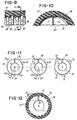
- FIGURES 9 and 10 there is shown an alternative form of discs 65 and 66.
- the discs 27, 49 and 52 can be modified as disclosed in FIGURES 9 and 10.
- the discs 65 and 66 have different outside diameters, with the discs 66 having a slightly larger diameter than the discs 65.
- a sleeve 67 is like the sleeves 23 and 63 in that it is under hoop tension and is ink receptive.
- the purpose of the different diameters is to promote the transference of ink from the capillary chambers 68 to the sleeve 67.
- the difference in the diameters of the discs 65 and 66 is on the order of 0.005 inch.
- FIGURE 11 shows a developed view of a series of discs in which alternate discs 70 and 71 have undulating peripheries having high points 72 and low points 73.
- the discs 70 and 71 also have passages 74 like the passages 49 and 62.
- the high points 72 have a pitch P of 20 degrees and consequently the low points also have a pitch of 20 degrees.
- FIGURE 11 shows the high points 72 of the discs 70 aligned, and out of alignment with the high point 72 of the disc 71.
- FIGURES 11 and 12 The provision of discs with a variable peripheral edge configuration as shown in FIGURES 11 and 12 is applicable to both the embodiment of FIGURES 1 through 4 and the embodiment of FIGURES 5 through 8. Such variable edge configurations promote flow of ink from capillary passages 74 to the porous sleeve 75.
- the spacing between the discs of the above disclosed embodiments be less than 0.02 inch and most preferably about 0.016 inch.
- the passages 27', 48', 65 and 74 are about 0.006 inch in width and extend from the shaft to the outer peripheries of the discs 27, 48, 52, 70 and 71.
- the discs 27, 48, 52, 70 and 71 are preferably about 0.012 inch in thickness.
Landscapes
- Impression-Transfer Materials And Handling Thereof (AREA)
Applications Claiming Priority (2)
| Application Number | Priority Date | Filing Date | Title |
|---|---|---|---|
| US08/988,256 US5906161A (en) | 1997-12-10 | 1997-12-10 | Ink roller assembly |
| US988256 | 1997-12-10 |
Publications (3)
| Publication Number | Publication Date |
|---|---|
| EP0922579A2 true EP0922579A2 (de) | 1999-06-16 |
| EP0922579A3 EP0922579A3 (de) | 2000-04-05 |
| EP0922579B1 EP0922579B1 (de) | 2002-06-05 |
Family
ID=25533982
Family Applications (1)
| Application Number | Title | Priority Date | Filing Date |
|---|---|---|---|
| EP98122903A Expired - Lifetime EP0922579B1 (de) | 1997-12-10 | 1998-12-02 | Farbwalzenanordnung |
Country Status (4)
| Country | Link |
|---|---|
| US (1) | US5906161A (de) |
| EP (1) | EP0922579B1 (de) |
| CA (1) | CA2252114C (de) |
| DE (1) | DE69805738T2 (de) |
Cited By (1)
| Publication number | Priority date | Publication date | Assignee | Title |
|---|---|---|---|---|
| EP1050406A1 (de) * | 1999-04-08 | 2000-11-08 | Monarch Marking Systems, INC. | Tintenrolle und Druckverfahren |
Families Citing this family (31)
| Publication number | Priority date | Publication date | Assignee | Title |
|---|---|---|---|---|
| US6766842B1 (en) | 1996-08-22 | 2004-07-27 | Paxar Americas, Inc. | Hand-held labeler |
| DE102009027354B4 (de) * | 2009-06-30 | 2011-07-21 | K-D Hermann GmbH Contact Auszeichnungssysteme, 69434 | Handetikettiergerät |
| US8943957B2 (en) | 2011-03-04 | 2015-02-03 | The Procter & Gamble Company | Apparatus for applying indicia having a large color gamut on web substrates |
| US8943959B2 (en) | 2011-03-04 | 2015-02-03 | The Procter & Gamble Company | Unique process for printing multiple color indicia upon web substrates |
| US8833250B2 (en) | 2011-03-04 | 2014-09-16 | The Procter & Gamble Company | Apparatus for applying indicia having a large color gamut on web substrates |
| US8943958B2 (en) | 2011-03-04 | 2015-02-03 | The Procter & Gamble Company | Apparatus for applying indicia having a large color gamut on web substrates |
| US8758560B2 (en) | 2011-03-04 | 2014-06-24 | The Procter & Gamble Company | Web substrates having wide color gamut indicia printed thereon |
| US8916260B2 (en) | 2011-03-04 | 2014-12-23 | The Procter & Gamble Company | Web substrates having wide color gamut indicia printed thereon |
| US8839716B2 (en) | 2011-03-04 | 2014-09-23 | The Procter & Gamble Company | Apparatus for applying indicia having a large color gamut on web substrates |
| US8616126B2 (en) | 2011-03-04 | 2013-12-31 | The Procter & Gamble Company | Apparatus for applying indicia having a large color gamut on web substrates |
| US8665493B2 (en) | 2011-03-04 | 2014-03-04 | The Procter & Gamble Company | Web substrates having wide color gamut indicia printed thereon |
| US8920911B2 (en) | 2011-03-04 | 2014-12-30 | The Procter & Gamble Company | Web substrates having wide color gamut indicia printed thereon |
| US8916261B2 (en) | 2011-03-04 | 2014-12-23 | The Procter & Gamble Company | Web substrates having wide color gamut indicia printed thereon |
| US8839717B2 (en) | 2011-03-04 | 2014-09-23 | The Procter & Gamble Company | Unique process for printing multiple color indicia upon web substrates |
| US8927093B2 (en) | 2011-03-04 | 2015-01-06 | The Procter & Gamble Company | Web substrates having wide color gamut indicia printed thereon |
| US8985013B2 (en) | 2011-03-04 | 2015-03-24 | The Procter & Gamble Company | Apparatus for applying indicia having a large color gamut on web substrates |
| US8927092B2 (en) | 2011-03-04 | 2015-01-06 | The Procter & Gamble Company | Web substrates having wide color gamut indicia printed thereon |
| US8943960B2 (en) | 2011-03-04 | 2015-02-03 | The Procter & Gamble Company | Unique process for printing multiple color indicia upon web substrates |
| US8962124B2 (en) | 2011-03-04 | 2015-02-24 | The Procter & Gamble Company | Web substrates having wide color gamut indicia printed thereon |
| CN104149503B (zh) * | 2013-05-15 | 2017-04-12 | 山东新北洋信息技术股份有限公司 | 印油机构及具有该印油机构的滚印盖章装置 |
| US9085130B2 (en) | 2013-09-27 | 2015-07-21 | The Procter & Gamble Company | Optimized internally-fed high-speed rotary printing device |
| US9724907B2 (en) * | 2014-05-30 | 2017-08-08 | The Procter & Gamble Company | Customizable apparatus and method for printing fluids |
| US9937704B2 (en) * | 2014-05-30 | 2018-04-10 | The Procter & Gamble Company | Method for making a customizable apparatus for transporting and depositing fluids |
| US9724908B2 (en) * | 2014-05-30 | 2017-08-08 | The Procter & Gamble Company | Customizable apparatus and method for printing fluids |
| US9492835B2 (en) * | 2014-05-30 | 2016-11-15 | The Procter & Gamble Company | Customizable apparatus and method for transporting and depositing fluids |
| US9694380B2 (en) * | 2014-05-30 | 2017-07-04 | The Procter & Gamble Company | Customizable apparatus and method for transporting and depositing fluids |
| US9259911B2 (en) * | 2014-05-30 | 2016-02-16 | The Procter & Gamble Company | Customizable apparatus and method for transporting and depositing fluids |
| US10144016B2 (en) | 2015-10-30 | 2018-12-04 | The Procter & Gamble Company | Apparatus for non-contact printing of actives onto web materials and articles |
| EP3426212B1 (de) | 2016-03-11 | 2020-10-21 | The Procter and Gamble Company | Zusammengesetzte, texturierte vliesstoffbahnen |
| WO2020028734A1 (en) | 2018-08-03 | 2020-02-06 | The Procter & Gamble Company | Webs with compositions applied thereto |
| WO2020028735A1 (en) | 2018-08-03 | 2020-02-06 | The Procter & Gamble Company | Webs with compositions thereon |
Family Cites Families (13)
| Publication number | Priority date | Publication date | Assignee | Title |
|---|---|---|---|---|
| US1281003A (en) * | 1915-11-29 | 1918-10-08 | Miehle Printing Press & Mfg | Lithographic damping-roller. |
| US1643488A (en) * | 1927-03-11 | 1927-09-27 | Jas H Matthews & Company | Fountain inking roll |
| DE1145642B (de) * | 1959-03-03 | 1963-03-21 | Gottscho Inc Adolph | Farbrolle |
| US3783083A (en) * | 1971-06-23 | 1974-01-01 | Monarch Marking Systems Inc | Composite web of pressure sensitive labels |
| US3738269A (en) * | 1971-07-06 | 1973-06-12 | W Wagner | Printing inking members |
| US3957562A (en) * | 1973-07-18 | 1976-05-18 | Monarch Marking Systems, Inc. | Apparatus for printing and applying pressure sensitive labels |
| US4227457A (en) * | 1976-02-17 | 1980-10-14 | Monarch Marking Systems, Inc. | Inking mechanism |
| US4246842A (en) * | 1979-08-03 | 1981-01-27 | Dayco Corporation | Printing roller |
| CA1171318A (en) * | 1980-06-23 | 1984-07-24 | Paul H. Hamisch, Jr. | Ink roller and method of making same |
| US4399751A (en) * | 1981-11-18 | 1983-08-23 | Monarch Marking Systems, Inc. | Ink roller assembly with capillary ink supply |
| US4416201A (en) * | 1981-11-18 | 1983-11-22 | Monarch Marking Systems, Inc. | Ink roller assembly with capillary ink supply |
| US5190385A (en) * | 1990-07-30 | 1993-03-02 | Pentel Kabushiki Kaisha | Ink ribbon regenerating device |
| US5910227A (en) * | 1996-08-22 | 1999-06-08 | Monarch Marking Systems, Inc. | Hand-held labeler |
-
1997
- 1997-12-10 US US08/988,256 patent/US5906161A/en not_active Expired - Lifetime
-
1998
- 1998-11-25 CA CA002252114A patent/CA2252114C/en not_active Expired - Fee Related
- 1998-12-02 EP EP98122903A patent/EP0922579B1/de not_active Expired - Lifetime
- 1998-12-02 DE DE69805738T patent/DE69805738T2/de not_active Expired - Fee Related
Cited By (1)
| Publication number | Priority date | Publication date | Assignee | Title |
|---|---|---|---|---|
| EP1050406A1 (de) * | 1999-04-08 | 2000-11-08 | Monarch Marking Systems, INC. | Tintenrolle und Druckverfahren |
Also Published As
| Publication number | Publication date |
|---|---|
| CA2252114A1 (en) | 1999-06-10 |
| DE69805738D1 (de) | 2002-07-11 |
| DE69805738T2 (de) | 2003-02-06 |
| US5906161A (en) | 1999-05-25 |
| EP0922579A3 (de) | 2000-04-05 |
| EP0922579B1 (de) | 2002-06-05 |
| CA2252114C (en) | 2006-08-01 |
Similar Documents
| Publication | Publication Date | Title |
|---|---|---|
| US5906161A (en) | Ink roller assembly | |
| US6234078B1 (en) | Ink roller assembly having a plurality of sections each having a porous sleeve | |
| US4483053A (en) | Method of making an ink roller | |
| CA1203432A (en) | Ink roller assembly with capillary ink supply | |
| US4534094A (en) | Method of making an ink roller assembly with capillary ink supply | |
| US5314257A (en) | Printer cartridge assembly | |
| GB2123928A (en) | Ink rollers | |
| US5826515A (en) | Stamping device | |
| CA2248951A1 (en) | Tubular core assemblies for rolls of paper or other sheet material | |
| US6615719B1 (en) | Multi-function inking tools | |
| US7156796B2 (en) | Ink roller | |
| CA2255718A1 (en) | Plastic butterfly valve | |
| US4409896A (en) | Ink roller | |
| CA1192441A (en) | Ink roller assembly with capillary ink supply | |
| AUPR609101A0 (en) | A filter cartridge | |
| CA1171318A (en) | Ink roller and method of making same | |
| CA2356780C (en) | Painting roller assembly | |
| CA1278951C (en) | Printing mechanism | |
| US4121521A (en) | Inking wheel having resilient inker support | |
| CA1071468A (en) | Label printing and applying apparatus | |
| JPH0242459Y2 (de) | ||
| DE3315766A1 (de) | Mehrfarbendruckkopf fuer registriergeraete | |
| JPS6440369A (en) | Printing method and device | |
| US20100326298A1 (en) | Continuous ink stamping systems and methods with reconfigurable stamping assembly | |
| JPH0751330Y2 (ja) | 小型プリンタのインキング装置 |
Legal Events
| Date | Code | Title | Description |
|---|---|---|---|
| PUAI | Public reference made under article 153(3) epc to a published international application that has entered the european phase |
Free format text: ORIGINAL CODE: 0009012 |
|
| AK | Designated contracting states |
Kind code of ref document: A2 Designated state(s): DE FR GB NL |
|
| AX | Request for extension of the european patent |
Free format text: AL;LT;LV;MK;RO;SI |
|
| PUAL | Search report despatched |
Free format text: ORIGINAL CODE: 0009013 |
|
| AK | Designated contracting states |
Kind code of ref document: A3 Designated state(s): AT BE CH CY DE DK ES FI FR GB GR IE IT LI LU MC NL PT SE |
|
| AX | Request for extension of the european patent |
Free format text: AL;LT;LV;MK;RO;SI |
|
| RIC1 | Information provided on ipc code assigned before grant |
Free format text: 7B 41F 31/22 A, 7B 41K 3/60 B, 7B 41N 7/06 B, 7B 41K 1/50 B |
|
| 17P | Request for examination filed |
Effective date: 20000407 |
|
| RIN1 | Information on inventor provided before grant (corrected) |
Inventor name: KESSLER, JOHN RICHARD |
|
| AKX | Designation fees paid |
Free format text: DE FR GB NL |
|
| 17Q | First examination report despatched |
Effective date: 20001122 |
|
| GRAG | Despatch of communication of intention to grant |
Free format text: ORIGINAL CODE: EPIDOS AGRA |
|
| GRAG | Despatch of communication of intention to grant |
Free format text: ORIGINAL CODE: EPIDOS AGRA |
|
| GRAG | Despatch of communication of intention to grant |
Free format text: ORIGINAL CODE: EPIDOS AGRA |
|
| GRAH | Despatch of communication of intention to grant a patent |
Free format text: ORIGINAL CODE: EPIDOS IGRA |
|
| GRAH | Despatch of communication of intention to grant a patent |
Free format text: ORIGINAL CODE: EPIDOS IGRA |
|
| GRAA | (expected) grant |
Free format text: ORIGINAL CODE: 0009210 |
|
| AK | Designated contracting states |
Kind code of ref document: B1 Designated state(s): DE FR GB NL |
|
| REG | Reference to a national code |
Ref country code: GB Ref legal event code: FG4D |
|
| REF | Corresponds to: |
Ref document number: 69805738 Country of ref document: DE Date of ref document: 20020711 |
|
| ET | Fr: translation filed | ||
| PLBE | No opposition filed within time limit |
Free format text: ORIGINAL CODE: 0009261 |
|
| STAA | Information on the status of an ep patent application or granted ep patent |
Free format text: STATUS: NO OPPOSITION FILED WITHIN TIME LIMIT |
|
| 26N | No opposition filed |
Effective date: 20030306 |
|
| PGFP | Annual fee paid to national office [announced via postgrant information from national office to epo] |
Ref country code: NL Payment date: 20081223 Year of fee payment: 11 |
|
| PGFP | Annual fee paid to national office [announced via postgrant information from national office to epo] |
Ref country code: DE Payment date: 20090202 Year of fee payment: 11 |
|
| PGFP | Annual fee paid to national office [announced via postgrant information from national office to epo] |
Ref country code: GB Payment date: 20081229 Year of fee payment: 11 |
|
| PGFP | Annual fee paid to national office [announced via postgrant information from national office to epo] |
Ref country code: FR Payment date: 20081217 Year of fee payment: 11 |
|
| REG | Reference to a national code |
Ref country code: NL Ref legal event code: V1 Effective date: 20100701 |
|
| GBPC | Gb: european patent ceased through non-payment of renewal fee |
Effective date: 20091202 |
|
| REG | Reference to a national code |
Ref country code: FR Ref legal event code: ST Effective date: 20100831 |
|
| PG25 | Lapsed in a contracting state [announced via postgrant information from national office to epo] |
Ref country code: NL Free format text: LAPSE BECAUSE OF NON-PAYMENT OF DUE FEES Effective date: 20100701 Ref country code: FR Free format text: LAPSE BECAUSE OF NON-PAYMENT OF DUE FEES Effective date: 20091231 |
|
| PG25 | Lapsed in a contracting state [announced via postgrant information from national office to epo] |
Ref country code: DE Free format text: LAPSE BECAUSE OF NON-PAYMENT OF DUE FEES Effective date: 20100701 |
|
| PG25 | Lapsed in a contracting state [announced via postgrant information from national office to epo] |
Ref country code: GB Free format text: LAPSE BECAUSE OF NON-PAYMENT OF DUE FEES Effective date: 20091202 |