EP0922376B1 - Elektronisches vorschaltgerät für gasentladungslampen - Google Patents
Elektronisches vorschaltgerät für gasentladungslampen Download PDFInfo
- Publication number
- EP0922376B1 EP0922376B1 EP97942836A EP97942836A EP0922376B1 EP 0922376 B1 EP0922376 B1 EP 0922376B1 EP 97942836 A EP97942836 A EP 97942836A EP 97942836 A EP97942836 A EP 97942836A EP 0922376 B1 EP0922376 B1 EP 0922376B1
- Authority
- EP
- European Patent Office
- Prior art keywords
- gas discharge
- capacitor
- electronic ballast
- resonance
- winding
- Prior art date
- Legal status (The legal status is an assumption and is not a legal conclusion. Google has not performed a legal analysis and makes no representation as to the accuracy of the status listed.)
- Expired - Lifetime
Links
- 239000003990 capacitor Substances 0.000 claims abstract description 82
- 238000004804 winding Methods 0.000 claims abstract description 46
- 238000010438 heat treatment Methods 0.000 claims description 8
- 238000009499 grossing Methods 0.000 claims description 5
- 238000005259 measurement Methods 0.000 claims description 5
- 230000005669 field effect Effects 0.000 claims description 2
- 238000002955 isolation Methods 0.000 claims 1
- 230000000694 effects Effects 0.000 description 6
- 230000008878 coupling Effects 0.000 description 2
- 238000010168 coupling process Methods 0.000 description 2
- 238000005859 coupling reaction Methods 0.000 description 2
- 230000001419 dependent effect Effects 0.000 description 1
- 230000005611 electricity Effects 0.000 description 1
- 230000004907 flux Effects 0.000 description 1
- 238000012544 monitoring process Methods 0.000 description 1
- 230000005855 radiation Effects 0.000 description 1
- 230000009467 reduction Effects 0.000 description 1
- 230000001629 suppression Effects 0.000 description 1
- 238000011144 upstream manufacturing Methods 0.000 description 1
Images


Classifications
-
- H—ELECTRICITY
- H05—ELECTRIC TECHNIQUES NOT OTHERWISE PROVIDED FOR
- H05B—ELECTRIC HEATING; ELECTRIC LIGHT SOURCES NOT OTHERWISE PROVIDED FOR; CIRCUIT ARRANGEMENTS FOR ELECTRIC LIGHT SOURCES, IN GENERAL
- H05B41/00—Circuit arrangements or apparatus for igniting or operating discharge lamps
- H05B41/14—Circuit arrangements
- H05B41/26—Circuit arrangements in which the lamp is fed by power derived from DC by means of a converter, e.g. by high-voltage DC
- H05B41/28—Circuit arrangements in which the lamp is fed by power derived from DC by means of a converter, e.g. by high-voltage DC using static converters
- H05B41/295—Circuit arrangements in which the lamp is fed by power derived from DC by means of a converter, e.g. by high-voltage DC using static converters with semiconductor devices and specially adapted for lamps with preheating electrodes, e.g. for fluorescent lamps
Definitions
- the present invention relates to an electronic ballast for Gas discharge lamps.
- the invention relates to an electronic one Ballast for gas discharge lamps according to the preamble of claim 1.
- the Electronic ballast includes one to a supply voltage source connectable rectifier 1, for example a full bridge or Reusable rectifier.
- a supply voltage source connectable rectifier 1 At one output of the rectifier 1 is one Circuit arrangement of at least one first capacitor 2 and at least one second capacity 3 connected.
- This capacitor circuit arrangement is with a Series connection of two controllable switches 4 and 5 and a smoothing electrolytic capacitor connected.
- the two Switches 4 and 5 At the point of connection between the two Switches 4 and 5 are the actual load circuit with the gas discharge lamp to be controlled 8 and a resonance circuit with a resonance inductance 6 and one of the Gas discharge lamp connected in parallel resonant capacitor 7.
- a choke coil 11 can advantageously between the rectifier 1 and the first capacitor 2 be present.
- a diode 12 between the first capacitor 2 and the first switch 4 necessary.
- the function of this circuit is briefly explained below. Is the output voltage of the rectifier is less than the voltage at the series connection of the capacitors 2 and 3, energy from the capacitors 2, 3 to the smoothing capacitor 13 issued. Otherwise, the capacitors 2, 3 via the rectifier 1 generate energy taken from the supply network.
- the two controllable switches 4 and 5 are known to be alternately on and off, so that depending on the adjustable Switching frequency of the two switches 4 and 5 that output by the rectifier 1 DC voltage converted into a high-frequency AC voltage and the Gas discharge lamp 8 is supplied. Corresponds to the frequency of the supplied AC voltage of the resonance frequency of the resonance inductance 6 and the Resonance capacitor 7 existing series resonance circuit, the Voltage surge at the resonance capacitor 7 to ignite the Gas discharge lamp exploited. On the other hand, by changing the frequency of the AC voltage set the operating point for the gas discharge lamp, and so this be dimmed.
- Control capacitor functioning second capacitor 3 fulfills two functions. On the one hand determines its capacitance in addition to the inductance 6 and the capacitances of the capacitors 2 and 7 the resonance frequency of the series resonance circuit. On the other hand, it works Capacitor 3 together with the rectifier 1, the return capacitor 2 and the optionally provided throttle 11 as a harmonic filter that the Harmonic radiation in the supply network should be kept as low as possible. Thereby however, there are different or opposing requirements for the Dimensioning of the control capacitor 3, so that when dimensioning it either Reductions in terms of co-determination of the resonance frequency or in terms of Harmonic filter effect must be made. This is especially true during the Preheating and lighting the gas discharge lamp.
- Fig. 6 shows that at the connection point between the two Capacitors 2 and 3 a current I is fed in from starting the lamp up to whose operation can take very different values, which makes the operating point of the entire circuit arrangement is shifted.
- the lamp 8 can only on one only from the dimensioning of capacitors 2 and 3 and Series resonant circuit 6 and 7 and the smoothing capacitor 13 dependent operating point work optimally, i.e. the lamp only burns at this single operating point satisfactory and the harmonic content reflected back into the supply network kept within certain limits.
- the present invention is therefore based on the object of an electronic Specify ballast in which the disadvantages described above are avoided.
- the object of the present invention is an electronic one Ballast to be specified in which, when dimensioning the second capacitor 3 no cutbacks need to be made and where at the connection point current I fed between capacitors 2 and 3 during ignition or preheating the gas discharge lamp 8 is kept as low as possible.
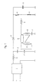
- Fig. 1 shows a first embodiment of the present invention.
- 6 already provided with the same reference numerals, so that a repeated description of these components can be dispensed with.
- Fig. 1 it can be seen that, in contrast to the known circuit Resonance capacitor 7 is no longer parallel to the gas discharge lamp 8, but in Series with one of two coupled windings 9, 10 of a transformer is connected. In 1, these two windings 9 and 10 are coupled in opposite directions. However, it will pointed out that the coupling sense is irrelevant for the effect to be sought here is.
- the left heating filament of the gas discharge lamp lies over the capacitor 3 AC to ground. The filament resistance of the left heating filament is determined by the transformer connected in parallel to the right winding 10 of the transformer, so that the Resonance capacitor 7 via the transformed spiral resistance of the left Heating coil rests on the right heating coil of the gas discharge lamp 8.
- FIG. 2a shows a variant of the first invention shown in FIG. 1 Embodiment for two gas discharge lamps 8 and 16, the corresponding essential components are duplicated.
- the second Gas discharge lamp 16 is another transformer with coupled windings 17 and 18 and a further load circuit with the second lamp 16 and another Resonance inductance and a further resonance capacitance 15 are provided.
- the optional choke coil 11 was dispensed with.
- the Resonance capacitors 7 and 15 and the second switch 5 a measuring resistor 19th intended. With the help of this resistor 19, both the arc current and the Preheating current can be measured.
- the arc current determines the brightness of the lamp, so that a measurement of this current for the monitoring and control of the Lamp brightness is of great importance.
- the resonance inductors 6 and 14 and the Resonance capacitors 7 and 15 at the same potential since they are connected to each other are.
- the arc current flows through the Measuring resistor 19 during the time when the switch 5 is closed and can thus at this time measured via the voltage drop across the measuring resistor 19 become.
- the preheating current flows when the lamp is open State of the switch 5 via the resonance capacitors 7, 15 which Resonance inductors 6, 14 and the closed switch 4.
- the preheating current is of particular interest in the preheating phase, so that with the invention Switching on one and the same both in the preheating phase and in the operating phase Component, namely the measuring resistor 19, the parameter of interest can be measured if the measurement time is selected correctly.
- the measurability of the parameters of interest in each case via the resistor 19 can are generally transferred to all circuit variants in which the Resonance capacitor is freely accessible, i.e. in an analogous manner, for example the circuit shown in FIG. 1, FIG. 26 or FIG. 5.
- FIG. 2b shows a further variant of the exemplary embodiment shown in FIG. 1 for two Gas discharge lamps, being for the second gas discharge lamp 16 on its own Transformer was omitted and instead this lamp on the one hand with the second Winding 10 of the transformer of the first lamp 8 connected and on the other hand with a own winding 17 is provided with the windings 9 and 10 of the transformer first gas discharge mask 8 is coupled.
- the Type of coupling for the effect according to the invention is irrelevant.
- a symmetrizing element connected upstream of both gas discharge lamps which advantageously from a balun with coils 20 coupled in opposite directions and 21.
- the balun serves to adjust the lamp currents two gas discharge lamps 8 and 16, so that both lamps evenly during operation burn.
- the two windings 20 and 21 of the Balancing transformer from the lamp currents of the two gas discharge lamps flowed through in the opposite direction, so that the balun from the lamp currents is magnetized in opposite directions.
- the second gas discharge lamp shown in Fig. 2a, b 16 is operated as the first gas discharge lamp 8, so that with reference to FIG. 1 described advantageous effects of the invention also on the second Gas discharge lamp 16 apply.
- Fig. 3 shows a second embodiment of the invention, wherein a transformer with three coupled windings 9, 10 and 22 is used.
- This embodiment is Particularly advantageous for radio interference suppression, since the gas discharge lamp 8 is above its left connection and the middle transformer winding 22 is set to ground.
- this embodiment for the measurability of voltages or currents on the individual circuit points advantageous because these sizes in this embodiment can be measured directly, while in the circuits of FIGS. 1 and 6 only one Measurement of these quantities as difference values is possible.
- three transformer windings are provided around the connection point one between the capacitors 2 and 3 in the case of preheating and in the event of ignition to supply little or no electricity at all.
- preheating and ignition i.e. if the lamp does not yet flow, the magnetic flux rises into the Transmitter windings 22, 10, which by the through the resonance inductance 6 and caused by the middle and right transformer winding 22, 10 flowing current because they have the same number of turns.
- the object of the invention is achieved that in the preheating and Ignition operation, the lowest possible current is supplied to the connection point. moreover it can be seen that the capacitor 3 does not match the resonance frequency of the Serial resonance circuit co-determined and thus only taking into account the Avoidance of harmonic reflections in the supply network can be.
- the number of turns of the left transformer winding 9 can be independent of that of the two other windings 22 and 10 are designed, so that in particular on this winding 9 the current to be fed to the connection point between the capacitors 2 and 3 can be adjusted.
- FIG. 4 shows a variant of the second embodiment for the operation of two Gas discharge lamps 8 and 16.
- there are four Transformer windings 9, 18, 22 and 10 required the effect of Circuit according to the invention for each gas discharge lamp based on FIG. 3 described advantageous effect corresponds.
- a is also in FIG Balancing transformer with oppositely coupled windings 20, 21 for balancing the lamp currents of the two lamps 8, 16 are provided.
- Fig. 5 shows a third embodiment of the electronic according to the invention Ballast.
- This exemplary embodiment is a further development of that in FIGS. 1 and 2 shown embodiment, but in addition to the two coupled
- a third coupled transformer winding 22 is provided for transformer windings 9 and 10 is.
- the measuring resistor 19 is again in series with the resonance capacitor 7 and the lower controllable switch 5, so that the resonance capacitor via the negligible in terms of size resistor 19 and the capacitor 3 the left connection of the gas discharge lamp 8 is connected and the Resonance capacitor 7 is, as it were, parallel to the gas discharge lamp 8.
- the gas discharge lamp 8 Exaggerated resonance can be ignited at the resonance capacitor 7.
- the above ground also abuts the lamp 8.
- the transmitter takes this over the Resonant capacitor 7 falling voltage with its primary winding 22 and sets them into a corresponding heating voltage on the two coils.
- each one of the two controllable switches 4 and 5, which are preferably MOS field effect transistors are bridged.
Landscapes
- Circuit Arrangements For Discharge Lamps (AREA)
- Discharge Lamp (AREA)
Description
Claims (18)
- Elektronisches Vorschaltgerät für Gasentladungslampen,gekennzeichnet durchmit einem an eine Versorgungsspannungsquelle anschließbaren Gleichrichter (1),mit einer mit dem Gleichrichter verbundenen Kondensator-Schaltungsanordnung aus wenigstens einem ersten Kondensator (2) und wenigstens einem zweiten Kondensator (3),mit einer mit der Kondensator-Schaltungsanordnung verbundenen Serienschaltung aus einem ersten steuerbaren Schalter (4) und einem zweiten steuerbaren Schalter (5), die wechselweise schaltbar sind, undmit einem an den Verbindungspunkt des ersten und zweiten Schalters angeschlossenen Lastkreis mit einem Serienresonanzkreis aus einer Resonanzinduktivität (6) und einem Resonanzkondensator (7) sowie einer daran angeschlossenen Gasentladungslampe (8),
einen Übertrager mit einer ersten Wicklung (9), die mit dem Verbindungspunkt zwischen dem ersten und zweiten Kondensator (2, 3) verbunden ist, und mit einer zweiten Wicklung (10), die mit dem Resonanzkondensator (7) verbunden ist. - Elektronisches Vorschaltgerät nach Anspruch 1,
daduch gekennzeichnet,
daß die erste Wicklung (9) des Übertragers zudem mit einer Wendel der Gasentladungslampe (8) und die zweite Wicklung (10) des Übertragers mit der anderen Wendel der Gasentladungslampe verbunden ist. (Fig. 1) - Elektronisches Vorschaltgerät nach Anspruch 1 oder 2,
gekennzeichnet durcheinen zwischen den Verbindungspunkt des ersten und zweiten Kondensators (2, 3) und den Verbindungspunkt des ersten und zweiten Schalters (4, 5) geschalteten weiteren Lastkreis mit einem weiteren Serienresonanzkreis aus einer weiteren Resonanzinduktivität (14) undeinem weiteren Resonanzkondensator (15) sowie einer daran angeschlossenen weiteren Gasentladungslampe (16), undeinen weiteren Übertrager mit einer ersten Wicklung (17), die mit dem Verbindungspunkt zwischen dem ersten und zweiten Kondensator (2, 3) verbunden ist, und mit einer zweiten Wicklung (18), die mit dem weiteren Resonanzkondensator (15) verbunden ist. (Fig. 2a) - Elektronisches Vorschaltgerät nach Anspruch 1 oder 2,
dadurch gekennzeichnet,daß zwischen dem Verbindungspunkt des ersten und zweiten Kondensators (2, 3) und dem Verbindungspunkt des ersten und zweiten Schalters (4, 5) ein weiterer Lastkreis geschaltet ist, der eine mit dem Serienresonanzkreis (6, 7) verbundene weitere Gasentladungslampe (16) umfaßt, unddaß der Übertrager eine dritte Wicklung (17) umfaßt, die mit dem Verbindungspunkt zwischen dem ersten und zweiten Kondensator (2, 3) sowie einer Wendel der weiteren Gasentladungslampe (16) verbunden ist. (Fig. 2b) - Elektronisches Vorschaltgerät nach Anspruch 1 oder 2,
dadurch gekennzeichnet, daß der Übertrager eine dritte Wicklung (22) umfaßt, die zu der Entladungsstrecke der Gasentladungslampe (8) parallel geschaltet ist. (Fig. 5) - Elektronisches Vorschaltgerät nach einem der vorhergehenden Ansprüche,
dadurch gekennzeichnet, daß der Resonanzkondensator (7) bzw. die Resonanzkondensatoren (7, 15) mit dem zweiten Schalter (5) und einem Meßwiderstand (19) verbunden ist bzw. sind. - Elektronisches Vorschaltgerät nach Anspruch 6,
dadurch gekennzeichnet, daß an dem Meßwiderstand (19) unmittelbar der Arc-Strom und der Vorheizstrom in Abhängigkeit vom Schaltzustand die Schalter 4, 5 meßbar ist. - Elektronisches Vorschaltgerät nach Anspruch 1,
dadurch gekennzeichnet, daß der Übertrager eine dritte Wicklung (22) umfaßt,wobei die eine Wendel der Gasentladungslampe (8) über die Serienschaltung aus der zweiten Wicklung (10) mit dem Resonanzkondensator (7) mit der anderen Wendel verbunden ist, undwobei die dritte Wicklung (22) mit der einen Wendel der Gasentladungslampe (8) verbunden ist. (Fig. 3) - Elektronisches Vorschaltgerät nach Anspruch 8,
dadurch gekennzeichnet, daß die zweite und dritte Wicklung (10, 22) dieselbe Windungszahl aufweisen. - Elektronisches Vorschaltgerät nach Anspruch 8 oder 9,
dadurch gekennzeichnet,daß mit der Resonanzinduktivität (6) des Lastkreises ein weiterer Lastkreis mit einem weiteren Resonanzkondensator (15) sowie einer daran angeschlossenen weiteren Gasentladungslampe (16) verbunden ist, unddaß der Übertrager eine vierte Wicklung (18) aufweist, wobei die eine Wendel der weiteren Gasentladungslampe (16) über eine Serienschaltung aus der vierten Wicklung (18) mit dem weiteren Resonanzkondensator (15) mit der anderen Wendel der weiteren Gasentladungslampe (16) verbunden ist, und wobei die dritte Wicklung (22) mit der einen Wendel der beiden Gasentladungslampen (8, 16) verbunden ist. (Fig. 4) - Elektronisches Vorschaltgerät nach einem der Ansprüche 3, 4 oder 10,
dadurch gekennzeichnet, daß den beiden Gasentladungslampen (8, 16) ein Symmetrierelement (20, 21), welches von den Lampenströmen der beiden Gasentladungslampen gegensinnig magnetisierbar ist, zugeordnet ist. - Elektronisches Vorschaltgerät nach Anspruch 11,
dadurch gekennzeichnet, daß das Symmetrierelement ein Symmetrierübertrager ist, dessen gegensinnig wirkenden Wicklungen (20, 21) an ihrem einen Ende miteinander und an ihrem anderen Ende mit der einen Wendel der entsprechenden Gasentladungslampe (8, 16) verbunden sind. - Elektronisches Vorschaltgerät nach einem der vorhergehenden Ansprüche,
dadurch gekennzeichnet, daß der erste und zweite steuerbare Schalter (4, 5) ein MOS-Feldeffekttransistor ist. - Elektronisches Vorschaltgerät nach einem der vorhergehenden Ansprüche,
dadurch gekennzeichnet, daß zwischen den Gleichrichter (1) und den ersten Kondensator (2) eine Drosselspule (11) geschaltet ist. - Elektronisches Vorschaltgerät nach einem der vorhergehenden Ansprüche,
dadurch gekennzeichnet, daß zwischen den ersten Kondensator (2) und den ersten Schalter (4) eine Diode (12) geschaltet ist. - Elektronisches Vorschaltgerät nach einem der vorhergehenden Ansprüche,
dadurch gekennzeichnet, daß ein Glättungskondensator (13) zu der Serienschaltung des ersten Schalters (4) mit dem zweiten Schalter (5) parallelgeschaltet ist. - Elektronisches Vorschaltgerät nach einem der vorhergehenden Ansprüche,
dadurch gekennzeichnet, daß zu dem ersten und zweiten Schalter (4, 5) jeweils eine Rücklaufdiode (24, 25) parallelgeschaltet ist. - Elektronisches Vorschaltgerät nach einem der vorhergehenden Ansprüche,
dadurch gekennzeichnet, daß mit der Resonanzinduktivität (6) bzw. den Resonanzinduktivitäten (6, 14) ein Trennkondensator (23) verbunden ist.
Applications Claiming Priority (3)
| Application Number | Priority Date | Filing Date | Title |
|---|---|---|---|
| DE19634850 | 1996-08-28 | ||
| DE19634850A DE19634850A1 (de) | 1996-08-28 | 1996-08-28 | Elektronisches Vorschaltgerät für Gasentladungslampen |
| PCT/EP1997/004150 WO1998009483A1 (de) | 1996-08-28 | 1997-07-30 | Elektronisches vorschaltgerät für gasentladungslampen |
Publications (2)
| Publication Number | Publication Date |
|---|---|
| EP0922376A1 EP0922376A1 (de) | 1999-06-16 |
| EP0922376B1 true EP0922376B1 (de) | 2002-03-20 |
Family
ID=7803969
Family Applications (1)
| Application Number | Title | Priority Date | Filing Date |
|---|---|---|---|
| EP97942836A Expired - Lifetime EP0922376B1 (de) | 1996-08-28 | 1997-07-30 | Elektronisches vorschaltgerät für gasentladungslampen |
Country Status (6)
| Country | Link |
|---|---|
| EP (1) | EP0922376B1 (de) |
| AT (1) | ATE214863T1 (de) |
| AU (1) | AU4453097A (de) |
| DE (2) | DE19634850A1 (de) |
| WO (1) | WO1998009483A1 (de) |
| ZA (1) | ZA977311B (de) |
Families Citing this family (4)
| Publication number | Priority date | Publication date | Assignee | Title |
|---|---|---|---|---|
| US20020153319A1 (en) | 1997-08-12 | 2002-10-24 | Debasish Mukhopadhyay | Method and apparatus for high efficiency reverse osmosis operation |
| US6111369A (en) * | 1998-12-18 | 2000-08-29 | Clalight Israel Ltd. | Electronic ballast |
| DE19916080C2 (de) * | 1999-04-09 | 2001-11-22 | Vossloh Schwabe Elektronik | Vorschaltgerät mit Fehlererkennung |
| DE102005060345A1 (de) | 2005-12-16 | 2007-06-21 | Patent-Treuhand-Gesellschaft für elektrische Glühlampen mbH | Schaltungsanordnung und Verfahren zum Betreiben mindestens einer ersten und einer zweiten Lampe |
Family Cites Families (4)
| Publication number | Priority date | Publication date | Assignee | Title |
|---|---|---|---|---|
| US5051662A (en) * | 1990-03-27 | 1991-09-24 | Usi Lighting, Inc. | Fluorescent lamp system |
| EP0602719B1 (de) * | 1992-12-16 | 1998-10-21 | Koninklijke Philips Electronics N.V. | Hochfrequenzumrichter für eine Entladungslampe mit vorheizbaren Elektroden |
| GB2279187A (en) * | 1993-06-19 | 1994-12-21 | Thorn Lighting Ltd | Fluorescent lamp starting and operating circuit |
| BE1009717A3 (nl) * | 1995-10-20 | 1997-07-01 | Philips Electronics Nv | Schakelinrichting. |
-
1996
- 1996-08-28 DE DE19634850A patent/DE19634850A1/de not_active Withdrawn
-
1997
- 1997-07-30 AU AU44530/97A patent/AU4453097A/en not_active Abandoned
- 1997-07-30 EP EP97942836A patent/EP0922376B1/de not_active Expired - Lifetime
- 1997-07-30 DE DE59706691T patent/DE59706691D1/de not_active Expired - Fee Related
- 1997-07-30 AT AT97942836T patent/ATE214863T1/de not_active IP Right Cessation
- 1997-07-30 WO PCT/EP1997/004150 patent/WO1998009483A1/de not_active Ceased
- 1997-08-14 ZA ZA9707311A patent/ZA977311B/xx unknown
Also Published As
| Publication number | Publication date |
|---|---|
| ZA977311B (en) | 1998-03-02 |
| WO1998009483A1 (de) | 1998-03-05 |
| DE19634850A1 (de) | 1998-03-05 |
| ATE214863T1 (de) | 2002-04-15 |
| EP0922376A1 (de) | 1999-06-16 |
| DE59706691D1 (de) | 2002-04-25 |
| AU4453097A (en) | 1998-03-19 |
Similar Documents
| Publication | Publication Date | Title |
|---|---|---|
| EP0264765B1 (de) | Schaltungsanordnung zum Betrieb von Niedervolt-Halogenglühlampen | |
| EP0347427B1 (de) | Schaltungsanordnung zum betrieb einer gasentladungslampe an einer gleichstromquelle | |
| DE3243316C2 (de) | Elektronisches Vorschaltgerät für Gasentladungslampen zum Steuern der Leistungsaufnahme derselben | |
| DE3407067C2 (de) | Steuerschaltung für Gasentladungslampen | |
| DE4328748B4 (de) | Wechselrichtereinheit | |
| DE69902379T2 (de) | Vorschaltgerät mit helligkeitssteuerung und regelverfahren für lampen unter verwendung eines frequenzgeregelten streufeldtransformators | |
| EP1330946B1 (de) | Schaltungsanordnung zum betreiben von mehreren gasentladungslampen | |
| EP0676121B1 (de) | Vorschaltgerät für mindestens ein parallel betriebenes gasentladungslampen-paar | |
| DE19923945A1 (de) | Elektronisches Vorschaltgerät für mindestens eine Niederdruck-Entladungslampe | |
| DE3829388A1 (de) | Schaltungsanordnung zum betrieb einer last | |
| EP1465330B1 (de) | Verfahren und Schaltung zum Variieren der Leistungsaufnahme von kapazitiven Lasten | |
| EP0439240A2 (de) | Elektronisches Vorschaltgerät | |
| DE3338464C2 (de) | Schaltungsanordnung zum Betrieb mindestens einer Leuchtstofflampe mit einstellbarer Helligkeit an einem selbstschwingenden Wechselrichter | |
| DE69312375T2 (de) | Steuerungsschaltung für eine Entladungslampe, insbesondere in Fahrzeugen | |
| EP0657091B1 (de) | Freischwingender wechselrichter mit impulsbreitensteuerung | |
| DE3719356A1 (de) | Schaltungsanordnung zum betrieb einer entladungslampe an einer niedervolt-gleichspannungsquelle | |
| EP0922376A1 (de) | Elektronisches vorschaltgerät für gasentladungslampen | |
| EP0121917A1 (de) | Elektronisches Vorschaltgerät für Leuchtstofflampen | |
| DE3504803A1 (de) | Gegentaktgenerator | |
| WO1993020677A1 (de) | Elektronisches vorschaltgerät für eine gasentladungslampe | |
| EP0155729B1 (de) | Schaltungsanordnung zum Wechselstrombetrieb von Hochdruckgasentladungslampen | |
| DE4126544A1 (de) | Stabilisierender elektronischer halbwellenconverter fuer ohmsche verbraucher mit diskreter oder breitbandiger hochfrequenter energieuebertragung | |
| EP1860925B1 (de) | Elektronisches Lampenvorschaltgerät mit Heizschaltung | |
| DE3614708A1 (de) | Steuerschaltung fuer eine lichtbogenlampe | |
| EP1961277B1 (de) | Schaltungsanordnung und verfahren zum betreiben mindestens einer ersten und einer zweiten lampe |
Legal Events
| Date | Code | Title | Description |
|---|---|---|---|
| PUAI | Public reference made under article 153(3) epc to a published international application that has entered the european phase |
Free format text: ORIGINAL CODE: 0009012 |
|
| 17P | Request for examination filed |
Effective date: 19981208 |
|
| AK | Designated contracting states |
Kind code of ref document: A1 Designated state(s): AT CH DE FR GB IT LI |
|
| GRAG | Despatch of communication of intention to grant |
Free format text: ORIGINAL CODE: EPIDOS AGRA |
|
| 17Q | First examination report despatched |
Effective date: 20010410 |
|
| GRAG | Despatch of communication of intention to grant |
Free format text: ORIGINAL CODE: EPIDOS AGRA |
|
| GRAH | Despatch of communication of intention to grant a patent |
Free format text: ORIGINAL CODE: EPIDOS IGRA |
|
| GRAH | Despatch of communication of intention to grant a patent |
Free format text: ORIGINAL CODE: EPIDOS IGRA |
|
| REG | Reference to a national code |
Ref country code: GB Ref legal event code: IF02 |
|
| GRAA | (expected) grant |
Free format text: ORIGINAL CODE: 0009210 |
|
| RIC1 | Information provided on ipc code assigned before grant |
Free format text: 7H 05B 41/292 A |
|
| AK | Designated contracting states |
Kind code of ref document: B1 Designated state(s): AT CH DE FR GB IT LI |
|
| REF | Corresponds to: |
Ref document number: 214863 Country of ref document: AT Date of ref document: 20020415 Kind code of ref document: T |
|
| REG | Reference to a national code |
Ref country code: CH Ref legal event code: NV Representative=s name: A. BRAUN, BRAUN, HERITIER, ESCHMANN AG PATENTANWAE Ref country code: CH Ref legal event code: EP |
|
| REF | Corresponds to: |
Ref document number: 59706691 Country of ref document: DE Date of ref document: 20020425 |
|
| ET | Fr: translation filed | ||
| GBT | Gb: translation of ep patent filed (gb section 77(6)(a)/1977) |
Effective date: 20020802 |
|
| PLBE | No opposition filed within time limit |
Free format text: ORIGINAL CODE: 0009261 |
|
| STAA | Information on the status of an ep patent application or granted ep patent |
Free format text: STATUS: NO OPPOSITION FILED WITHIN TIME LIMIT |
|
| 26N | No opposition filed |
Effective date: 20021223 |
|
| PGFP | Annual fee paid to national office [announced via postgrant information from national office to epo] |
Ref country code: CH Payment date: 20050722 Year of fee payment: 9 |
|
| PGFP | Annual fee paid to national office [announced via postgrant information from national office to epo] |
Ref country code: AT Payment date: 20050726 Year of fee payment: 9 |
|
| PG25 | Lapsed in a contracting state [announced via postgrant information from national office to epo] |
Ref country code: AT Free format text: LAPSE BECAUSE OF NON-PAYMENT OF DUE FEES Effective date: 20060730 |
|
| PG25 | Lapsed in a contracting state [announced via postgrant information from national office to epo] |
Ref country code: LI Free format text: LAPSE BECAUSE OF NON-PAYMENT OF DUE FEES Effective date: 20060731 Ref country code: CH Free format text: LAPSE BECAUSE OF NON-PAYMENT OF DUE FEES Effective date: 20060731 |
|
| REG | Reference to a national code |
Ref country code: CH Ref legal event code: PL |
|
| PGFP | Annual fee paid to national office [announced via postgrant information from national office to epo] |
Ref country code: IT Payment date: 20080726 Year of fee payment: 12 |
|
| PGFP | Annual fee paid to national office [announced via postgrant information from national office to epo] |
Ref country code: DE Payment date: 20080929 Year of fee payment: 12 |
|
| PGFP | Annual fee paid to national office [announced via postgrant information from national office to epo] |
Ref country code: FR Payment date: 20090720 Year of fee payment: 13 |
|
| PG25 | Lapsed in a contracting state [announced via postgrant information from national office to epo] |
Ref country code: DE Free format text: LAPSE BECAUSE OF NON-PAYMENT OF DUE FEES Effective date: 20100202 |
|
| PG25 | Lapsed in a contracting state [announced via postgrant information from national office to epo] |
Ref country code: IT Free format text: LAPSE BECAUSE OF NON-PAYMENT OF DUE FEES Effective date: 20090730 |
|
| REG | Reference to a national code |
Ref country code: FR Ref legal event code: ST Effective date: 20110331 |
|
| PG25 | Lapsed in a contracting state [announced via postgrant information from national office to epo] |
Ref country code: FR Free format text: LAPSE BECAUSE OF NON-PAYMENT OF DUE FEES Effective date: 20100802 |
|
| PGFP | Annual fee paid to national office [announced via postgrant information from national office to epo] |
Ref country code: GB Payment date: 20140729 Year of fee payment: 18 |
|
| GBPC | Gb: european patent ceased through non-payment of renewal fee |
Effective date: 20150730 |
|
| PG25 | Lapsed in a contracting state [announced via postgrant information from national office to epo] |
Ref country code: GB Free format text: LAPSE BECAUSE OF NON-PAYMENT OF DUE FEES Effective date: 20150730 |