EP0921767B1 - Intramedulläre, flexible bruchfixierungsvorrichtung, mit biaxialer vorspannung - Google Patents
Intramedulläre, flexible bruchfixierungsvorrichtung, mit biaxialer vorspannung Download PDFInfo
- Publication number
- EP0921767B1 EP0921767B1 EP97929435A EP97929435A EP0921767B1 EP 0921767 B1 EP0921767 B1 EP 0921767B1 EP 97929435 A EP97929435 A EP 97929435A EP 97929435 A EP97929435 A EP 97929435A EP 0921767 B1 EP0921767 B1 EP 0921767B1
- Authority
- EP
- European Patent Office
- Prior art keywords
- tendon
- prestressing
- bone
- anchor
- anchor means
- Prior art date
- Legal status (The legal status is an assumption and is not a legal conclusion. Google has not performed a legal analysis and makes no representation as to the accuracy of the status listed.)
- Expired - Lifetime
Links
- 210000000988 bone and bone Anatomy 0.000 claims abstract description 59
- 210000002435 tendon Anatomy 0.000 claims abstract description 52
- 230000006835 compression Effects 0.000 claims abstract description 20
- 238000007906 compression Methods 0.000 claims abstract description 20
- 238000004873 anchoring Methods 0.000 claims abstract description 3
- 230000000063 preceeding effect Effects 0.000 claims 3
- 239000011248 coating agent Substances 0.000 claims 1
- 238000000576 coating method Methods 0.000 claims 1
- 208000010392 Bone Fractures Diseases 0.000 abstract description 26
- 239000012634 fragment Substances 0.000 abstract description 12
- 208000008924 Femoral Fractures Diseases 0.000 abstract description 5
- 230000033001 locomotion Effects 0.000 abstract description 5
- 230000036316 preload Effects 0.000 abstract description 4
- 206010017076 Fracture Diseases 0.000 description 20
- 238000000034 method Methods 0.000 description 5
- 238000005452 bending Methods 0.000 description 4
- 238000010008 shearing Methods 0.000 description 4
- 210000000689 upper leg Anatomy 0.000 description 4
- 206010016454 Femur fracture Diseases 0.000 description 3
- 208000007101 Muscle Cramp Diseases 0.000 description 3
- 208000005392 Spasm Diseases 0.000 description 3
- 238000006386 neutralization reaction Methods 0.000 description 2
- 238000007747 plating Methods 0.000 description 2
- 230000017531 blood circulation Effects 0.000 description 1
- 230000003292 diminished effect Effects 0.000 description 1
- 210000002436 femur neck Anatomy 0.000 description 1
- 210000000527 greater trochanter Anatomy 0.000 description 1
- 230000035876 healing Effects 0.000 description 1
- 239000007943 implant Substances 0.000 description 1
- 208000015181 infectious disease Diseases 0.000 description 1
- 239000002184 metal Substances 0.000 description 1
- 238000004321 preservation Methods 0.000 description 1
- 238000011084 recovery Methods 0.000 description 1
- 210000004872 soft tissue Anatomy 0.000 description 1
- 230000003319 supportive effect Effects 0.000 description 1
- 230000035899 viability Effects 0.000 description 1
Images




Classifications
-
- A—HUMAN NECESSITIES
- A61—MEDICAL OR VETERINARY SCIENCE; HYGIENE
- A61B—DIAGNOSIS; SURGERY; IDENTIFICATION
- A61B17/00—Surgical instruments, devices or methods
- A61B17/56—Surgical instruments or methods for treatment of bones or joints; Devices specially adapted therefor
- A61B17/58—Surgical instruments or methods for treatment of bones or joints; Devices specially adapted therefor for osteosynthesis, e.g. bone plates, screws or setting implements
- A61B17/68—Internal fixation devices, including fasteners and spinal fixators, even if a part thereof projects from the skin
- A61B17/72—Intramedullary devices, e.g. pins or nails
- A61B17/7216—Intramedullary devices, e.g. pins or nails for bone lengthening or compression
- A61B17/7225—Intramedullary devices, e.g. pins or nails for bone lengthening or compression for bone compression
-
- A—HUMAN NECESSITIES
- A61—MEDICAL OR VETERINARY SCIENCE; HYGIENE
- A61B—DIAGNOSIS; SURGERY; IDENTIFICATION
- A61B17/00—Surgical instruments, devices or methods
- A61B17/56—Surgical instruments or methods for treatment of bones or joints; Devices specially adapted therefor
- A61B17/58—Surgical instruments or methods for treatment of bones or joints; Devices specially adapted therefor for osteosynthesis, e.g. bone plates, screws or setting implements
- A61B17/68—Internal fixation devices, including fasteners and spinal fixators, even if a part thereof projects from the skin
- A61B17/72—Intramedullary devices, e.g. pins or nails
- A61B17/7233—Intramedullary devices, e.g. pins or nails with special means of locking the nail to the bone
- A61B17/7258—Intramedullary devices, e.g. pins or nails with special means of locking the nail to the bone with laterally expanding parts, e.g. for gripping the bone
- A61B17/7266—Intramedullary devices, e.g. pins or nails with special means of locking the nail to the bone with laterally expanding parts, e.g. for gripping the bone with fingers moving radially outwardly
-
- A—HUMAN NECESSITIES
- A61—MEDICAL OR VETERINARY SCIENCE; HYGIENE
- A61B—DIAGNOSIS; SURGERY; IDENTIFICATION
- A61B17/00—Surgical instruments, devices or methods
- A61B17/56—Surgical instruments or methods for treatment of bones or joints; Devices specially adapted therefor
- A61B17/58—Surgical instruments or methods for treatment of bones or joints; Devices specially adapted therefor for osteosynthesis, e.g. bone plates, screws or setting implements
- A61B17/68—Internal fixation devices, including fasteners and spinal fixators, even if a part thereof projects from the skin
- A61B17/74—Devices for the head or neck or trochanter of the femur
- A61B17/742—Devices for the head or neck or trochanter of the femur having one or more longitudinal elements oriented along or parallel to the axis of the neck
- A61B17/746—Devices for the head or neck or trochanter of the femur having one or more longitudinal elements oriented along or parallel to the axis of the neck the longitudinal elements coupled to a plate opposite the femoral head
Definitions
- the invention refers to a prosthetic device for the application of simultaneous axial and transversal prestressing to preload the bone and obtain stable and elastic osteosynthesis of fractures.
- the device focuses on the concept of biological internal fixation with minimal damage and with consideration for the natural frequency (Hz) of the bone.
- Document DE-C-923085 discloses such a prosthetic device comprising a tendon in form of a band, deformable elements, compression means and anchor means at the first end of the tendon as well as tension means.
- the tendon is a tension wire. If a tension force is exercised on this wire, the distance between a ring and the top end of the device is diminished whereby deformable elements are moved transversally.
- the top or a second end of the tendon however is not screwed or in any way anchored in the bone and therefore is not clear, how the bone fragments hold together, when the deformable elements are transversally opened, because they cause forces, which distract the bone ends.
- This invention aims to add to the theory and practice of bone fixation the concept that the fracture fixation device introduces into the broken bone equilibrium tensions to restore the intraosseous forces and make the bone capable of receiving the load stresses and muscle-spasm stresses right at the beginning of the healing period, as opposed to the prior concept that it is the device that receives these stresses.
- the object of the invention is an intramedullary, flexible fracture fixation device, which supports the bone in an axial, lateral and transversal direction in a controlled manner and avoids bone reaming. Moreover, the tendon should be precisely anchored in the bone.
- the invention discloses in combination a device for fracture fixation, where a plurality of cylindrical elements are disposed around the tendon, whereby the end of the anchor means is provided with a thread to immobilise the anchor of the device.
- a prosthetic device of the invention it is possible to apply simultaneously axial and transversal pre-stressing to pre-load the bone and obtain stable and elastic ostheosynthesis of fractures.
- the device focuses on the concept of biological internal fixation with a minimal damage and with consideration for the natural frequency of the bone.
- the device for fracture fixation comprises, a tendon and at least a deformable element at the focus of the fracture, whereby the deformable elements may be 2, 3, 4, 5, or more, with the tendon and the deformable element being disposed almost along the same direction, whereby the device further comprises compression means to apply a compression force to the deformable elements, so that the deformable elements deforms laterally.
- the device described can be used for fractures of long bones as well as for proximal femoral fractures.
- the device When used for long bone fractures, the device is an intramedullar flexible bar, by which we apply adjustable and readable axial prestressing in order to compress the bone fragments and preload the bone, and not a supportive intramedullar nail as the devices used sofar for fracture fixation.
- the device When used for proximal femoral fractures, the device is the same intramedullar flexible bar, by which we apply adjustable and readable lateral prestressing when anchoring it on the external femoral shaft. By doing so we compress the bone fragments in order to neutralize the tension forces on the fracture and to avoid the interfragmentary motions.
- the terms “axial prestressing” and “lateral prestressing” refer to the axis of the long bone.
- the device according to the invention presents a different approach to the problem of fracture fixation in that it allows us to achieve predetermined and readable intramedular transversal prestressing, which is a prerequisite for the application either of axial prestressing or of lateral prestressing.
- the transversal prestressing holds in place the repositioned bone fragments and contributes to the neutralization of the bending moments and the shearing forces between the fracture angle and the mechanical axis of the bone caused by the axial prestressing in the case of long bone fractures.
- the transversal prestressing diminishes the interfragmentary motions.
- the term "transversal prestressing” refers to the "axial prestressing” and the "lateral prestressing” and is vertical to them.
- the same device can be used as bone distractor for unstable long bone fractures.
- the one end of the tendon is anchored at the end of the cylinder other than the end bearing the screw.
- the tendon is anchored by a ball means in order to form an articulation at this point and thus diminish the motion between implant and bone.
- the tendon bends on the lateral femoral shaft with support on a fulcrum attached on a plate, which plate is screwed in the lateral femoral shaft.
- the other end of the tendon passes through a cylinder fixed to the plate. We exercise tension on this end of the tendon with support on the cylinder fixed to the plate and we then anchor the tendon on the plate (lateral prestressing).
- a second tension band wire
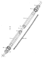
- the tendon 1 for the application of axial prestressing can be a wire-cable. Its one end is incorporated into an anchor means 2 , which may be a self-taping screw, suitable for spongy bone.
- the head of the anchor means is cylindrical with two slots 4 , dividing the perimeter of the cylinder into two protrusions which fit into the two slots of the preceding cylindrical body 3 .
- the other end of the tendon is incorporated into a screw means 2a , for example a threaded bar.
- the tendon is passing through cylinders.
- the two cylinders 6, 7, which correspond to the focus of the fracture, have an overdrawn perimeter for part of their length, to provide place for attachment means 8 , in which the deformable laminated springs 9 are adapted.
- the length of the slots of these two cylinders on the end where they fit into one another is longer, so as to allow them to come closer, compress the laminated springs and let them bow and exercise intramedullary pressure.
- the torque means 5 placed last towards the end of the device near the body is of similar shape to the cylinders 3 along half of its length.
- the other half of its length, towards the end of the device, has the shape of a screw nut as regards its external shape.
- a nut screwdriver is adapted to this half of the torque means 5 to screw the anchor means 2 , by screwing the whole device around itself.
- the internal cylindrical opening of the part of the torque means 5 which fits into the cylinder 3 is of the same diameter as the openings of all the other cylinders so as to allow the tendon to pass through, whereas the part of the internal opening towards the end of the device is larger to let the threaded bar 2a adapted to the tendon fit into it and be stopped there so as to hold all the cylinders together.
- a nut 10 is screwed around the threaded bar 2a to bring all the cylindrical bodies 3,6,7 and torque means 5 together and compress laminated springs 9 , which by deforming laterally, exercise intramedullar pressure, i.e. transversal prestressing.
- the bolt 11 is then screwed around the bar 2a after the nut 10, to apply tension to the tendon 1 with support on the anchor means 12 and on the bone, thus exercising axial prestressing, that is pre-loading of the bone.
- Bolt 11 may be replaced by element 11a with grooves on its outer side.
- the element 11a when screwed inside the anchor means 12 and by compressing the bar 2a , it applies compression forces to the device, thus distracting the bone fragments when necessary.
- the tendon 1b for the application of lateral prestressing can be a wire cable. Its one end may have the form of a ball which is attached to a bolt 18, which bolt is screwed around torque means 5b. Torque means 5b is actually the one end of an anchor means 2b, and serves to screw the anchor means into the bone. The other end of the anchor means 2b may be a self-taping screw, suitable for spongy bone.
- the body of the anchor means 2b is hollow because the anchor means is positioned with the help of a drill guide.
- deformable elements 9b are disposed almost along the same direction, which are fixed at both their ends into attachment means 8b.
- a plate 14 is fixed with screws on the lateral cortex of the femur.
- This plate differs from the usual ones in two points. First it has a protrusion 15 on its head, which serves as a fulcrum for the tendon 1b to have a smooth change of direction of the tendon. Second, there is a cylinder 16 fixed on the plate' s body. The tendon 1b is passing through this cylinder. We exercise tension (lateral prestressing) on the tendon along its axis, with support against the cylinder 16 . This tension may be easily measured and adjusted according to the necessities of the direction of the fracture, the weight of the patient and the form, dimensions and quality of the bone.
- This tension can be applied by means of a dynamometric tensioner, which in this case plays the role of a tension means.
- a tension means we then anchor the tendon on the plate with a securing means 17.
- This securing means 17 may be in the form of a deformable metal clip or cylinder, which can be deformed and pressed on the tendon in a fixed relationship.
Landscapes
- Health & Medical Sciences (AREA)
- Orthopedic Medicine & Surgery (AREA)
- Surgery (AREA)
- Life Sciences & Earth Sciences (AREA)
- Heart & Thoracic Surgery (AREA)
- Animal Behavior & Ethology (AREA)
- Engineering & Computer Science (AREA)
- Biomedical Technology (AREA)
- Neurology (AREA)
- Medical Informatics (AREA)
- Molecular Biology (AREA)
- Nuclear Medicine, Radiotherapy & Molecular Imaging (AREA)
- General Health & Medical Sciences (AREA)
- Public Health (AREA)
- Veterinary Medicine (AREA)
- Surgical Instruments (AREA)
- Laminated Bodies (AREA)
- Prostheses (AREA)
Claims (15)
- Vorrichtung zum Fixieren von Frakturen mitdadurch gekennzeichnet, dasseiner Sehne (1, 1b) mit einem ersten und einem zweiten Ende,einer Vielzahl zylindrischer Elemente (3, 5, 6, 7), die um die Sehne herum auf sie aufgesetzt sind,mindestens einem verformbaren Element (9, 9b), das angenähert in Richtung der Sehne angeordnet ist,einer Kompressionseinrichtung (2a, 3, 5, 6, 7, 10, 10b), mit der eine Kompressionskraft auf das mindestens eine verformbare Element aufbringbar ist derart, dass letzteres sich seitlich verformt, so dass die Sehne die Fraktur axial vorspannt und das mindestens eine verformbare Element am Fokus der Fraktur eine seitliche Vorspannung aufbringt,einer Ankereinrichtung (2, 2a) zum Verankern der Sehne (1, 1b) undeiner Spanneinrichtung (11) zum Spannen der Sehne (1, 1b),
die Kompressionseinrichtung (2a, 3, 5, 6, 7, 10, 10b) an zwei zylindrischen Elementen eine Ansetzeinrichtung (8) aufweist, mit der die beiden Enden des verformbaren Elements (9, 9b) an diese zwei zylindrischen Elemente ansetzbar sind,
die Kompressionseinrichtung mit einer Schraubeinrichtung (2a) zusammenwirkt derart, dass beim Verschrauben der Kompressionseinrichtung auf letzterer die Vielzahl der zylindrischen Elemente sich einander nähern, um das mindestens eine verformbare Element (9, 9b) zu komprimieren und dadurch seitlich zu verformen, so dass eine transversale Vorspannung mit intramedullärem Druck ausgeübt wird,
und dass die Ankereinrichtung (2) mit einem Gewinde versehen ist, um den Anker der Vorrichtung zu immobilisieren. - Vorrichtung nach Anspruch 1, bei der die Spanneinrichtung (11) eine erste Ankereinrichtung (2) am ersten Ende der Sehne (1) und eine Schraubeinrichtung (2a) am zweiten Ende der Sehne aufweist.
- Vorrichtung nach Anspruch 1, bei der die Spanneinrichtung eine erste Ankereinrichtung (2b) am ersten Ende der Sehne (1b) aufweist.
- Vorrichtung nach Anspruch 1 mit einer ersten Ankereinrichtung (2, 2b) am ersten Ende der Sehne (1, 1b) und mit einer Verdreheinrichtung (5, 5b), mittels der ein Drehmoment auf die Ankereinrichtung (2, 2b) aufbringbar ist, um die Vorrichtung um sich selbst zu drehen und der ersten Ankereinrichtung zu verschrauben.
- Vorrichtung nach Anspruch 1, bei der die verformbaren Elemente (9b) an beiden Enden an Ansetzeinrichtungen (8b) befestigt sind, die mit der Kompressionseinrichtung (10b) zusammenwirken, um die verformbaren Elemente (9b) zu komprimieren und seitlich zu verformen.
- Vorrichtung nach Anspruch 1 mit einer Bolzeneinrichtung (11) und einer am Ende der Sehne angeordneten zweiten Ankereinrichtung (12), die die Schraubeinrichtung trägt, wobei die Bolzen- und die zweite Ankereinrichtung mit der Schraubeinrichtung (2a) zusammenwirken, um eine Spannkraft auf die Sehne aufzubringen.
- Vorrichtung nach einem vorgehenden Anspruch weiterhin mit einer dritten Ankereinrichtung (14, 16) und einer Sicherungseinrichtung (17) am der ersten Ankereinrichtung entgegengesetzten Ende der Sehne, wobei die Ankereinrichtung (14, 16) und die Sicherungseinrichtung (17) zusammenwirken, um die auf die Sehne aufgebrachte Spannkraft zu erhalten.
- Vorrichtung nach Anspruch 1, bei der mindestens zwei zylindrische Elemente zwei Schlitze (4) an ihren beiden Enden aufweisen, so dass an den Enden der zylindrischen Elemente abwechselnde Vorsprünge und Schlitze vorliegen, die mit entsprechenden Schlitzen bzw. Vorsprüngen des angrenzenden zylindrischen Elements zusammenwirken, damit die zylindrischen Elemente ineinander passen und einen biegsamen Stab bilden.
- Vorrichtung nach Anspruch 1, 3 oder 4 weiterhin mit einem Bolzen (18), der auf das eine Ende der ersten Ankereinrichtung (2b) aufgeschraubt wird, wobei das erste Ende der Sehne (1b) die Form einer Kugel hat, die in den Bolzen (18) eingeschlossen ist.
- Vorrichtung nach Anspruch 8, bei der zwei zylindrische Elemente (6, 7) in dem Ende, wo sie ineinander passen, längere Schlitze (4) enthalten, die ihnen erlauben, sich zu nähern und die verformbaren Elemente zu komprimieren.
- Vorrichtung nach Anspruch 8, deren erste Ankereinrichtung (2) einen zylindrischen Kopf mit Schlitzen (4) aufweist, um in das vorgehende zylindrische Element (3) zu passen.
- Vorrichtung nach einem der vorgehenden Ansprüche mit mehr als einem verformbaren Element (9, 9b), wobei die verformbaren Elemente (9, 9b) parallel zueinander um den Umfang der Ankereinrichtung (2, 2b) positioniert sind.
- Vorrichtung nach Anspruch 7, bei der die dritte Ankereinrichtung eine Platte (14) und einen an dieser befestigten Zylinder (16) aufweist.
- Vorrichtung nach Anspruch 13, deren Platte (14) einen Aufsatz (15) als Umlenkpunkt für die Sehne (1b) aufweist.
- Vorrichtung nach einem beliebigen vorhergehenden Anspruch, deren gesamter außerhalb des Knochens befindlicher Teil von einer biokompatiblen Platte abgedeckt ist, die eine glatte Außenfläche herstellt.
Applications Claiming Priority (3)
| Application Number | Priority Date | Filing Date | Title |
|---|---|---|---|
| GR96100234 | 1996-07-10 | ||
| GR96100234 | 1996-07-10 | ||
| PCT/GR1997/000026 WO1998001077A1 (en) | 1996-07-10 | 1997-07-09 | Intramedullary, flexible fracture fixation device, using bi-axial prestressing |
Publications (2)
| Publication Number | Publication Date |
|---|---|
| EP0921767A1 EP0921767A1 (de) | 1999-06-16 |
| EP0921767B1 true EP0921767B1 (de) | 2003-10-22 |
Family
ID=10942443
Family Applications (1)
| Application Number | Title | Priority Date | Filing Date |
|---|---|---|---|
| EP97929435A Expired - Lifetime EP0921767B1 (de) | 1996-07-10 | 1997-07-09 | Intramedulläre, flexible bruchfixierungsvorrichtung, mit biaxialer vorspannung |
Country Status (8)
| Country | Link |
|---|---|
| US (1) | US6224600B1 (de) |
| EP (1) | EP0921767B1 (de) |
| JP (1) | JP2001509040A (de) |
| AT (1) | ATE252347T1 (de) |
| CA (1) | CA2259907A1 (de) |
| DE (1) | DE69725736D1 (de) |
| GR (1) | GR1003032B (de) |
| WO (1) | WO1998001077A1 (de) |
Families Citing this family (76)
| Publication number | Priority date | Publication date | Assignee | Title |
|---|---|---|---|---|
| US6554833B2 (en) * | 1998-10-26 | 2003-04-29 | Expanding Orthopedics, Inc. | Expandable orthopedic device |
| JP4262595B2 (ja) | 1998-10-26 | 2009-05-13 | エクスパンディング オーソペディクス インコーポレーテッド | 拡開可能な整形外科用装置 |
| AU2000235484B2 (en) * | 2000-04-10 | 2004-10-14 | Synthes Gmbh | Osteosynthetic anchoring element |
| US6551321B1 (en) * | 2000-06-23 | 2003-04-22 | Centerpulse Orthopedics Inc. | Flexible intramedullary nail |
| US20030153918A1 (en) * | 2002-02-14 | 2003-08-14 | Putnam Matthew D. | Volar fixation plate |
| JP2006520983A (ja) * | 2003-03-18 | 2006-09-14 | コーニンクレッカ フィリップス エレクトロニクス エヌ ヴィ | 光記録担体の平坦化ヒートシンクまたは反射層 |
| US7101376B2 (en) * | 2003-04-04 | 2006-09-05 | Elliot Charles Semet | Interlocking IM Nails with threaded guidewire |
| US7695471B2 (en) * | 2003-04-18 | 2010-04-13 | The University Of Hong Kong | Fixation device |
| EP1629133A4 (de) * | 2003-04-18 | 2007-04-18 | Univ Hong Kong | Formgedächtnismaterial und herstellungsverfahren dafür |
| AU2003285364A1 (en) * | 2003-11-25 | 2005-06-24 | Javier Ara Pinilla | Intramedullary nail |
| JP2007517634A (ja) | 2004-01-16 | 2007-07-05 | エクスパンディング オーソペディクス インコーポレーテッド | 骨折治療デバイス |
| US7632277B2 (en) * | 2004-03-29 | 2009-12-15 | Woll Bioorthopedics Llc | Orthopedic intramedullary fixation system |
| AU2004319780A1 (en) * | 2004-05-19 | 2005-11-24 | Sintea Biotech S.P.A | Intravertebral widening device, injection device, and kit and method for kyphoplasty |
| EP1753354B1 (de) * | 2004-05-21 | 2010-09-15 | Myers Surgical Solutions, LLC | Frakturfixations- und situsstabilisationssystem |
| US7481841B2 (en) * | 2004-06-30 | 2009-01-27 | Depuy Products, Inc. | Adjustable orthopaedic prosthesis and associated method |
| US7559951B2 (en) * | 2004-09-30 | 2009-07-14 | Depuy Products, Inc. | Adjustable, remote-controllable orthopaedic prosthesis and associated method |
| DE202004019105U1 (de) * | 2004-12-10 | 2005-02-24 | Stryker Trauma Gmbh | Vorrichtung zum Räumen von Knochenhöhlen |
| EP1876975A2 (de) * | 2005-04-27 | 2008-01-16 | James Marino | Verfahren, system und satz mit einer monoplanaren pedikelschraube |
| US9060820B2 (en) | 2005-05-18 | 2015-06-23 | Sonoma Orthopedic Products, Inc. | Segmented intramedullary fracture fixation devices and methods |
| US8961516B2 (en) | 2005-05-18 | 2015-02-24 | Sonoma Orthopedic Products, Inc. | Straight intramedullary fracture fixation devices and methods |
| US7846162B2 (en) | 2005-05-18 | 2010-12-07 | Sonoma Orthopedic Products, Inc. | Minimally invasive actuable bone fixation devices |
| NL1030218C2 (nl) * | 2005-10-18 | 2007-04-19 | Gert Dr Ir Nijenbanning | Medisch apparaat voor het behandelen van gebroken beenderen danwel het bevestigen van stabiliserende elementen aan botdelen. |
| CA2670263A1 (en) | 2006-11-22 | 2008-05-29 | Sonoma Orthopedic Products, Inc. | Fracture fixation device, tools and methods |
| EP3300676A1 (de) | 2007-03-12 | 2018-04-04 | Stout Medical Group, L.P. | Ausziehbare befestigungsvorrichtung |
| JP2010522046A (ja) * | 2007-03-22 | 2010-07-01 | ノヴァリン・オルソペディクス・インコーポレーテッド | セグメント状髄内構造体 |
| WO2009059227A1 (en) * | 2007-11-02 | 2009-05-07 | Stout Medical Group, L.P. | Expandable attachment device and method |
| CN103271761B (zh) | 2008-01-14 | 2015-10-28 | 康文图斯整形外科公司 | 用于骨折修补的装置和方法 |
| EP2299917A1 (de) | 2008-06-10 | 2011-03-30 | Sonoma Orthopedic Products, Inc. | Frakturfixationsvorrichtung, werkzeuge und verfahren |
| AU2009296243A1 (en) | 2008-09-26 | 2010-04-01 | Sonoma Orthopedic Products, Inc. | Bone fixation device, tools and methods |
| US8221420B2 (en) * | 2009-02-16 | 2012-07-17 | Aoi Medical, Inc. | Trauma nail accumulator |
| US9622798B2 (en) * | 2009-02-17 | 2017-04-18 | Gregory Merrell | Intramedullary compression rod |
| US20110307072A1 (en) * | 2009-02-26 | 2011-12-15 | Deputy International Limited | Support structure implant for a bone cavity |
| US8012155B2 (en) * | 2009-04-02 | 2011-09-06 | Zimmer, Inc. | Apparatus and method for prophylactic hip fixation |
| US8545499B2 (en) * | 2009-09-28 | 2013-10-01 | Zimmer, Inc. | Expandable intramedullary rod |
| WO2011088172A1 (en) | 2010-01-15 | 2011-07-21 | Brenzel Michael P | Rotary-rigid orthopaedic rod |
| EP2523616B1 (de) | 2010-01-20 | 2019-04-17 | Conventus Orthopaedics, Inc. | Vorrichtung zum zugriff auf knochen und zur herstellung von hohlräumen darin |
| JP2013521880A (ja) * | 2010-03-08 | 2013-06-13 | コンベンタス オーソピディックス, インコーポレイテッド | 骨インプラントを固定するための装置および方法 |
| US9072564B2 (en) | 2010-06-02 | 2015-07-07 | Wright Medical Technology, Inc. | Hammer toe implant and method |
| US9498273B2 (en) | 2010-06-02 | 2016-11-22 | Wright Medical Technology, Inc. | Orthopedic implant kit |
| US9724140B2 (en) | 2010-06-02 | 2017-08-08 | Wright Medical Technology, Inc. | Tapered, cylindrical cruciform hammer toe implant and method |
| US8608785B2 (en) | 2010-06-02 | 2013-12-17 | Wright Medical Technology, Inc. | Hammer toe implant with expansion portion for retrograde approach |
| US9138219B2 (en) | 2010-12-29 | 2015-09-22 | Tarsus Medical Inc. | Methods and devices for treating a syndesmosis injury |
| US9144506B2 (en) * | 2011-08-11 | 2015-09-29 | Jeff Phelps | Interbody axis cage |
| US20130090690A1 (en) * | 2011-10-06 | 2013-04-11 | David A. Walsh | Dynamic Rod Assembly |
| US9393126B2 (en) * | 2012-04-20 | 2016-07-19 | Peter L. Mayer | Bilaterally placed disc prosthesis for spinal implant and method of bilateral placement |
| US9364339B2 (en) * | 2012-04-30 | 2016-06-14 | Peter L. Mayer | Unilaterally placed expansile spinal prosthesis |
| US8840612B2 (en) * | 2012-05-04 | 2014-09-23 | William L. Tontz | Intraosseous expandable fixation device |
| US8945232B2 (en) | 2012-12-31 | 2015-02-03 | Wright Medical Technology, Inc. | Ball and socket implants for correction of hammer toes and claw toes |
| WO2014124328A1 (en) | 2013-02-08 | 2014-08-14 | Gorsline Robert | Systems, methods, apparatuses for fusion, stabilization, or fixation of bones |
| WO2014134584A1 (en) | 2013-02-28 | 2014-09-04 | Feibel Jonathan | Systems, methods, and apparatuses for reaming bone elements |
| KR101394321B1 (ko) * | 2013-04-05 | 2014-05-14 | 중앙대학교 산학협력단 | 골접합 장치 |
| US9724139B2 (en) | 2013-10-01 | 2017-08-08 | Wright Medical Technology, Inc. | Hammer toe implant and method |
| US9474561B2 (en) | 2013-11-19 | 2016-10-25 | Wright Medical Technology, Inc. | Two-wire technique for installing hammertoe implant |
| JP6539652B2 (ja) | 2013-12-12 | 2019-07-03 | コンベンタス オーソピディックス, インコーポレイテッド | 組織変位ツールおよび方法 |
| US9770278B2 (en) | 2014-01-17 | 2017-09-26 | Arthrex, Inc. | Dual tip guide wire |
| US9545274B2 (en) * | 2014-02-12 | 2017-01-17 | Wright Medical Technology, Inc. | Intramedullary implant, system, and method for inserting an implant into a bone |
| US9498266B2 (en) | 2014-02-12 | 2016-11-22 | Wright Medical Technology, Inc. | Intramedullary implant, system, and method for inserting an implant into a bone |
| WO2016043751A1 (en) | 2014-09-18 | 2016-03-24 | Wright Medical Technology, Inc. | Hammertoe implant and instrument |
| US9814499B2 (en) | 2014-09-30 | 2017-11-14 | Arthrex, Inc. | Intramedullary fracture fixation devices and methods |
| CA2889595C (en) | 2014-12-19 | 2018-01-16 | Wright Medical Technology, Inc. | Intramedullary anchor for interphalangeal arthrodesis |
| US10492838B2 (en) | 2015-07-13 | 2019-12-03 | IntraFuse, LLC | Flexible bone implant |
| US10485595B2 (en) | 2015-07-13 | 2019-11-26 | IntraFuse, LLC | Flexible bone screw |
| US10499960B2 (en) | 2015-07-13 | 2019-12-10 | IntraFuse, LLC | Method of bone fixation |
| US10154863B2 (en) | 2015-07-13 | 2018-12-18 | IntraFuse, LLC | Flexible bone screw |
| AU2017323632B2 (en) * | 2016-09-08 | 2021-11-04 | Meduloc, Llc | Implant and method for long bone fixation |
| US10631881B2 (en) | 2017-03-09 | 2020-04-28 | Flower Orthopedics Corporation | Plating depth gauge and countersink instrument |
| WO2019010252A2 (en) | 2017-07-04 | 2019-01-10 | Conventus Orthopaedics, Inc. | Apparatus and methods for treatment of a bone |
| EP3664733A4 (de) * | 2017-08-09 | 2021-04-07 | Panther Orthopedics, Inc. | Befestigungsmöglichkeiten für knochen- und gelenkstabilisierungsvorrichtung |
| US10888363B2 (en) | 2017-12-06 | 2021-01-12 | Stout Medical Group, L.P. | Attachment device and method for use |
| US11291488B1 (en) | 2021-02-24 | 2022-04-05 | Medshape, Inc. | Dynamic compression devices and processes for making and using same |
| CN113143545B (zh) * | 2021-05-10 | 2025-02-07 | 北京智康汇成科技有限公司 | 干骺端骨缺损髓内轴向加压固定假体 |
| US12527606B1 (en) * | 2021-08-26 | 2026-01-20 | Medshape, Inc. | System and method for bone fixation based on bone quality |
| CN115919438A (zh) * | 2022-11-25 | 2023-04-07 | 北京纳通医疗科技控股有限公司 | 骨折复位装置 |
| US12178485B1 (en) * | 2023-08-26 | 2024-12-31 | University Of Utah Research Foundation | Cannulated continuous compression screw |
| US20250331903A1 (en) * | 2024-04-29 | 2025-10-30 | DePuy Synthes Products, Inc. | Methods and devices for bone fixation |
| US20260020885A1 (en) * | 2024-07-16 | 2026-01-22 | DePuy Synthes Products, Inc. | Devices and methods for bone fixation |
Family Cites Families (8)
| Publication number | Priority date | Publication date | Assignee | Title |
|---|---|---|---|---|
| DE923085C (de) * | 1939-12-17 | 1955-02-03 | Ernst Dr Med H C Pohl | Innenschiene fuer Roehrenknochen |
| AT353394B (de) * | 1975-12-18 | 1979-11-12 | Helmut Haemmerle | Knochennagel |
| IL54025A0 (en) * | 1978-02-12 | 1978-04-30 | Aginsky Yacov | Connector for fractured bones |
| US4632101A (en) * | 1985-01-31 | 1986-12-30 | Yosef Freedland | Orthopedic fastener |
| US5057103A (en) * | 1990-05-01 | 1991-10-15 | Davis Emsley A | Compressive intramedullary nail |
| DE4209122A1 (de) * | 1992-03-20 | 1993-09-23 | Kessler Sigurd | Marknagel |
| GB2268068B (en) * | 1992-07-01 | 1996-08-21 | John Bruce Clayfield Davies | Devices having expansion means for securing end portions of tubular members |
| DE4423210A1 (de) * | 1994-07-01 | 1996-01-04 | Sigurd Dr Kesler | Fixierungs- und Positionierungssystem für intramedulläre Kraftträger |
-
1996
- 1996-07-10 GR GR960100234A patent/GR1003032B/el not_active IP Right Cessation
-
1997
- 1997-07-09 WO PCT/GR1997/000026 patent/WO1998001077A1/en not_active Ceased
- 1997-07-09 EP EP97929435A patent/EP0921767B1/de not_active Expired - Lifetime
- 1997-07-09 AT AT97929435T patent/ATE252347T1/de not_active IP Right Cessation
- 1997-07-09 CA CA002259907A patent/CA2259907A1/en not_active Abandoned
- 1997-07-09 JP JP50495898A patent/JP2001509040A/ja active Pending
- 1997-07-09 DE DE69725736T patent/DE69725736D1/de not_active Expired - Lifetime
- 1997-07-09 US US09/214,600 patent/US6224600B1/en not_active Expired - Fee Related
Also Published As
| Publication number | Publication date |
|---|---|
| JP2001509040A (ja) | 2001-07-10 |
| CA2259907A1 (en) | 1998-01-15 |
| DE69725736D1 (de) | 2003-11-27 |
| GR1003032B (el) | 1998-12-16 |
| WO1998001077A1 (en) | 1998-01-15 |
| US6224600B1 (en) | 2001-05-01 |
| EP0921767A1 (de) | 1999-06-16 |
| ATE252347T1 (de) | 2003-11-15 |
| GR960100234A (el) | 1998-03-31 |
Similar Documents
| Publication | Publication Date | Title |
|---|---|---|
| US6224600B1 (en) | Intramedullary, flexible fracture fixation device, using bi-axial prestressing | |
| US11806008B2 (en) | Devices for generating and applying compression within a body | |
| HULSE et al. | Reduction in plate strain by addition of an intramedullary pin | |
| US5190545A (en) | Cerclage wire positioning insert | |
| US9204899B2 (en) | Segmental orthopedic device for spinal elongation and for treatment of scoliosis | |
| US7785325B1 (en) | Multi-articulated fracture fixation device with adjustable modulus of rigidity | |
| US8372074B2 (en) | Multi-articulated fracture fixation device with adjustable modulus of rigidity | |
| EP2197373B1 (de) | Knochenfixiersystem | |
| JP4598760B2 (ja) | 調整ロッド及びコネクタ機器、並びにその使用方法 | |
| JP5602735B2 (ja) | 骨固定器具 | |
| Perren | The biomechanics and biology of internal fixation using plates and nails | |
| US20250099225A1 (en) | Ligament fixation system, implants, devices, and methods of use | |
| US20090326584A1 (en) | Spinal Dynamic Stabilization Rods Having Interior Bumpers | |
| KR20060020596A (ko) | 뼈 또는 뼈 분절, 특히 흉곽 척추의 동적 안정화 장치 | |
| AU2010218343A1 (en) | Multiple bone fusion plate | |
| WO2005034796A2 (en) | Bone fixation plates | |
| Gardner et al. | The influence of external fixators on fracture motion during simulated walking | |
| CA2029897A1 (en) | Setting device for tubular bone fractures | |
| Lins et al. | A comparative mechanical analysis of plate fixation in a proximal phalangeal fracture model | |
| Schatzker | Principles of internal fixation | |
| US20220378482A1 (en) | Orthopedic bone tap and methods incorporating the same | |
| WO1996009012A1 (en) | Fixation plate for long bone fractures and method of use | |
| Williamson Jr et al. | Biomechanics of the spine and spinal instrumentation | |
| Auer | New Implant Systems | |
| Baker | Extended use of the k wire and the orthopaedic screw:: the Fixclip™ Project |
Legal Events
| Date | Code | Title | Description |
|---|---|---|---|
| PUAI | Public reference made under article 153(3) epc to a published international application that has entered the european phase |
Free format text: ORIGINAL CODE: 0009012 |
|
| 17P | Request for examination filed |
Effective date: 19990104 |
|
| AK | Designated contracting states |
Kind code of ref document: A1 Designated state(s): AT BE CH DE DK ES FI FR GB GR IE IT LI LU MC NL PT SE |
|
| 17Q | First examination report despatched |
Effective date: 20020305 |
|
| GRAH | Despatch of communication of intention to grant a patent |
Free format text: ORIGINAL CODE: EPIDOS IGRA |
|
| GRAS | Grant fee paid |
Free format text: ORIGINAL CODE: EPIDOSNIGR3 |
|
| GRAA | (expected) grant |
Free format text: ORIGINAL CODE: 0009210 |
|
| AK | Designated contracting states |
Kind code of ref document: B1 Designated state(s): AT BE CH DE DK ES FI FR GB GR IE IT LI LU MC NL PT SE |
|
| PG25 | Lapsed in a contracting state [announced via postgrant information from national office to epo] |
Ref country code: NL Free format text: LAPSE BECAUSE OF FAILURE TO SUBMIT A TRANSLATION OF THE DESCRIPTION OR TO PAY THE FEE WITHIN THE PRESCRIBED TIME-LIMIT Effective date: 20031022 Ref country code: LI Free format text: LAPSE BECAUSE OF FAILURE TO SUBMIT A TRANSLATION OF THE DESCRIPTION OR TO PAY THE FEE WITHIN THE PRESCRIBED TIME-LIMIT Effective date: 20031022 Ref country code: IT Free format text: LAPSE BECAUSE OF FAILURE TO SUBMIT A TRANSLATION OF THE DESCRIPTION OR TO PAY THE FEE WITHIN THE PRESCRIBED TIME-LIMIT;WARNING: LAPSES OF ITALIAN PATENTS WITH EFFECTIVE DATE BEFORE 2007 MAY HAVE OCCURRED AT ANY TIME BEFORE 2007. THE CORRECT EFFECTIVE DATE MAY BE DIFFERENT FROM THE ONE RECORDED. Effective date: 20031022 Ref country code: FR Free format text: LAPSE BECAUSE OF FAILURE TO SUBMIT A TRANSLATION OF THE DESCRIPTION OR TO PAY THE FEE WITHIN THE PRESCRIBED TIME-LIMIT Effective date: 20031022 Ref country code: FI Free format text: LAPSE BECAUSE OF FAILURE TO SUBMIT A TRANSLATION OF THE DESCRIPTION OR TO PAY THE FEE WITHIN THE PRESCRIBED TIME-LIMIT Effective date: 20031022 Ref country code: CH Free format text: LAPSE BECAUSE OF FAILURE TO SUBMIT A TRANSLATION OF THE DESCRIPTION OR TO PAY THE FEE WITHIN THE PRESCRIBED TIME-LIMIT Effective date: 20031022 Ref country code: BE Free format text: LAPSE BECAUSE OF FAILURE TO SUBMIT A TRANSLATION OF THE DESCRIPTION OR TO PAY THE FEE WITHIN THE PRESCRIBED TIME-LIMIT Effective date: 20031022 Ref country code: AT Free format text: LAPSE BECAUSE OF FAILURE TO SUBMIT A TRANSLATION OF THE DESCRIPTION OR TO PAY THE FEE WITHIN THE PRESCRIBED TIME-LIMIT Effective date: 20031022 |
|
| REG | Reference to a national code |
Ref country code: GB Ref legal event code: FG4D |
|
| REG | Reference to a national code |
Ref country code: CH Ref legal event code: EP |
|
| REG | Reference to a national code |
Ref country code: IE Ref legal event code: FG4D |
|
| REF | Corresponds to: |
Ref document number: 69725736 Country of ref document: DE Date of ref document: 20031127 Kind code of ref document: P |
|
| PG25 | Lapsed in a contracting state [announced via postgrant information from national office to epo] |
Ref country code: SE Free format text: LAPSE BECAUSE OF FAILURE TO SUBMIT A TRANSLATION OF THE DESCRIPTION OR TO PAY THE FEE WITHIN THE PRESCRIBED TIME-LIMIT Effective date: 20040122 Ref country code: GR Free format text: LAPSE BECAUSE OF FAILURE TO SUBMIT A TRANSLATION OF THE DESCRIPTION OR TO PAY THE FEE WITHIN THE PRESCRIBED TIME-LIMIT Effective date: 20040122 Ref country code: DK Free format text: LAPSE BECAUSE OF FAILURE TO SUBMIT A TRANSLATION OF THE DESCRIPTION OR TO PAY THE FEE WITHIN THE PRESCRIBED TIME-LIMIT Effective date: 20040122 |
|
| PG25 | Lapsed in a contracting state [announced via postgrant information from national office to epo] |
Ref country code: DE Free format text: LAPSE BECAUSE OF FAILURE TO SUBMIT A TRANSLATION OF THE DESCRIPTION OR TO PAY THE FEE WITHIN THE PRESCRIBED TIME-LIMIT Effective date: 20040123 |
|
| PG25 | Lapsed in a contracting state [announced via postgrant information from national office to epo] |
Ref country code: ES Free format text: LAPSE BECAUSE OF FAILURE TO SUBMIT A TRANSLATION OF THE DESCRIPTION OR TO PAY THE FEE WITHIN THE PRESCRIBED TIME-LIMIT Effective date: 20040202 |
|
| NLV1 | Nl: lapsed or annulled due to failure to fulfill the requirements of art. 29p and 29m of the patents act | ||
| REG | Reference to a national code |
Ref country code: CH Ref legal event code: PL |
|
| PG25 | Lapsed in a contracting state [announced via postgrant information from national office to epo] |
Ref country code: LU Free format text: LAPSE BECAUSE OF NON-PAYMENT OF DUE FEES Effective date: 20040709 Ref country code: IE Free format text: LAPSE BECAUSE OF NON-PAYMENT OF DUE FEES Effective date: 20040709 Ref country code: GB Free format text: LAPSE BECAUSE OF NON-PAYMENT OF DUE FEES Effective date: 20040709 |
|
| PG25 | Lapsed in a contracting state [announced via postgrant information from national office to epo] |
Ref country code: MC Free format text: LAPSE BECAUSE OF NON-PAYMENT OF DUE FEES Effective date: 20040731 |
|
| PLBE | No opposition filed within time limit |
Free format text: ORIGINAL CODE: 0009261 |
|
| STAA | Information on the status of an ep patent application or granted ep patent |
Free format text: STATUS: NO OPPOSITION FILED WITHIN TIME LIMIT |
|
| 26N | No opposition filed |
Effective date: 20040723 |
|
| EN | Fr: translation not filed | ||
| GBPC | Gb: european patent ceased through non-payment of renewal fee |
Effective date: 20040709 |
|
| REG | Reference to a national code |
Ref country code: IE Ref legal event code: MM4A |
|
| PG25 | Lapsed in a contracting state [announced via postgrant information from national office to epo] |
Ref country code: PT Free format text: LAPSE BECAUSE OF NON-PAYMENT OF DUE FEES Effective date: 20040322 |