EP0921332B1 - Molybdenum alloy elevator safety brakes - Google Patents
Molybdenum alloy elevator safety brakes Download PDFInfo
- Publication number
- EP0921332B1 EP0921332B1 EP98309034A EP98309034A EP0921332B1 EP 0921332 B1 EP0921332 B1 EP 0921332B1 EP 98309034 A EP98309034 A EP 98309034A EP 98309034 A EP98309034 A EP 98309034A EP 0921332 B1 EP0921332 B1 EP 0921332B1
- Authority
- EP
- European Patent Office
- Prior art keywords
- brake
- base
- friction
- friction surface
- attached
- Prior art date
- Legal status (The legal status is an assumption and is not a legal conclusion. Google has not performed a legal analysis and makes no representation as to the accuracy of the status listed.)
- Expired - Lifetime
Links
- 229910001182 Mo alloy Inorganic materials 0.000 title claims description 16
- 239000000463 material Substances 0.000 claims description 19
- 239000000956 alloy Substances 0.000 claims description 14
- 239000002783 friction material Substances 0.000 claims description 13
- ZOKXTWBITQBERF-UHFFFAOYSA-N Molybdenum Chemical compound [Mo] ZOKXTWBITQBERF-UHFFFAOYSA-N 0.000 claims description 3
- RTAQQCXQSZGOHL-UHFFFAOYSA-N Titanium Chemical compound [Ti] RTAQQCXQSZGOHL-UHFFFAOYSA-N 0.000 claims description 3
- QCWXUUIWCKQGHC-UHFFFAOYSA-N Zirconium Chemical compound [Zr] QCWXUUIWCKQGHC-UHFFFAOYSA-N 0.000 claims description 3
- 229910052750 molybdenum Inorganic materials 0.000 claims description 3
- 239000011733 molybdenum Substances 0.000 claims description 3
- 229910052719 titanium Inorganic materials 0.000 claims description 3
- 239000010936 titanium Substances 0.000 claims description 3
- 229910052726 zirconium Inorganic materials 0.000 claims description 3
- 229910001060 Gray iron Inorganic materials 0.000 description 7
- 229910000831 Steel Inorganic materials 0.000 description 5
- 239000010959 steel Substances 0.000 description 5
- 229910001018 Cast iron Inorganic materials 0.000 description 3
- 229910045601 alloy Inorganic materials 0.000 description 1
- 230000004927 fusion Effects 0.000 description 1
- 238000010438 heat treatment Methods 0.000 description 1
- 238000012986 modification Methods 0.000 description 1
- 230000004048 modification Effects 0.000 description 1
- 230000035939 shock Effects 0.000 description 1
- 239000000758 substrate Substances 0.000 description 1
- 238000012876 topography Methods 0.000 description 1
Images

Classifications
-
- F—MECHANICAL ENGINEERING; LIGHTING; HEATING; WEAPONS; BLASTING
- F16—ENGINEERING ELEMENTS AND UNITS; GENERAL MEASURES FOR PRODUCING AND MAINTAINING EFFECTIVE FUNCTIONING OF MACHINES OR INSTALLATIONS; THERMAL INSULATION IN GENERAL
- F16D—COUPLINGS FOR TRANSMITTING ROTATION; CLUTCHES; BRAKES
- F16D69/00—Friction linings; Attachment thereof; Selection of coacting friction substances or surfaces
- F16D69/02—Composition of linings ; Methods of manufacturing
- F16D69/027—Compositions based on metals or inorganic oxides
-
- B—PERFORMING OPERATIONS; TRANSPORTING
- B66—HOISTING; LIFTING; HAULING
- B66B—ELEVATORS; ESCALATORS OR MOVING WALKWAYS
- B66B5/00—Applications of checking, fault-correcting, or safety devices in elevators
- B66B5/02—Applications of checking, fault-correcting, or safety devices in elevators responsive to abnormal operating conditions
- B66B5/16—Braking or catch devices operating between cars, cages, or skips and fixed guide elements or surfaces in hoistway or well
- B66B5/18—Braking or catch devices operating between cars, cages, or skips and fixed guide elements or surfaces in hoistway or well and applying frictional retarding forces
- B66B5/22—Braking or catch devices operating between cars, cages, or skips and fixed guide elements or surfaces in hoistway or well and applying frictional retarding forces by means of linearly-movable wedges
-
- F—MECHANICAL ENGINEERING; LIGHTING; HEATING; WEAPONS; BLASTING
- F16—ENGINEERING ELEMENTS AND UNITS; GENERAL MEASURES FOR PRODUCING AND MAINTAINING EFFECTIVE FUNCTIONING OF MACHINES OR INSTALLATIONS; THERMAL INSULATION IN GENERAL
- F16D—COUPLINGS FOR TRANSMITTING ROTATION; CLUTCHES; BRAKES
- F16D69/00—Friction linings; Attachment thereof; Selection of coacting friction substances or surfaces
- F16D2069/002—Combination of different friction materials
Definitions
- GB-A-2 287 451 discloses an emergency stop apparatus for an elevator in which the friction material of the brake shoe comprises a molybdenum alloy.
- FIG. 1 provides a simplified schematic illustration of a known elevator safety brake system upon which the present invention may be used.
- the brake system 10 comprises a pair of actuators 12 which are attached to an elevator car 14 and positioned in an opposing relationship about a guide rail 16 supported in an elevator hoistway (not shown).
- the actuators 12 are formed, in part, by a wedge shaped guide shoe 18 which is movable within housing 20 in a direction which is generally perpendicular to the guide rail 16.
- the guide shoe 18 is biased towards the guide rail 16 by spring 22.
- the guide shoe 18 has an inclined support surface 24 .
- a wedge shaped brake shoe 25 having base 26 is provided with an inclined guiding surface 28 which is complimentary to the inclined support surface 24 of the guide shoe 18 .
- the brake shoe 25 is also provided with a rail facing surface 30 .
- a force F A in the direction of the elevator car 14 is applied to the base 26 of the wedge shaped brake shoes 25 which causes the shoes 25 to move towards the elevator car 14.
- force F A is supplied by a rope, cable or mechanical linkage connected to a governor (not shown).
- the inclined complimentary surfaces 24 and 28 of the guide shoe 18 and the brake shoe base 26 respectively, cause the brake shoe 25 to move towards the rail 16 until contact between the pad 32 and the rail 16 is made.
- the pad 32 is applied to the rail 16 with normal force F N supplied by the spring 22.
- the brake pad 32 used in the brake system 10 to provide a friction surface has been formed from gray cast iron.
- Gray cast iron while suitable for low speed, low load conditions, cannot operate as a consistent friction material at high speed and load conditions.
- the gray cast iron material used as the high friction material in pads 32 may be replaced with a molybdenum alloy material.
- a brake pad having a molybdenum alloy material according to the present invention which will be described more fully below, is capable of operation under the conditions required for an elevator operating at contract speeds of up to 10 meters per second with a load rating of up to 16000 Kg. It has been further found that the pads made in accordance with the present invention have significant mechanical toughness, thermal shock resistance, negligible wear rates on rail steel and appreciable coefficient of friction on rail steel.
- the test tile was loaded with a normal force of 11,000 N against a rotating 2 meter diameter disk under conditions which were selected to simulate an emergency stop on a typical steel hoistway guide rail surface under high load and high velocity conditions.
- a frictional force of nearly 6,000 N was generated which indicates that the material had a nominal coefficient of friction with the rail steel of about 0.40 which is about 1.5 times that of typical gray cast iron grade 30.
- the TZM molybdenum alloy tile showed very little wear, about 1 percent of the wear exhibited by the typical gray cast iron grade 30.
- the rail damage caused by the molybdenum alloy was equivalent to the damage caused by grade 30 cast iron.
- the material performed adequately under all rail conditions simulated (clean rail, rusted rail, oiled rail, wet rail and roughened rail).
- the friction surface of the brake may be in the form of a plate 34 which is attached to the base 26.
- a cross hatch pattern 36 may be machined therein to provide a topography to the friction surface.
- the friction surface may be formed from a plurality of tiles 38 of the TZM alloy material.
- the tiles 38 may be attached to the base 26 directly via mechanical fasteners (not shown) or alternatively, the tiles may be attached to the base 26 via a compliant material interface 40 which enables resilient movement of the alloy friction material relative to the base 26 and allows a greater number of tiles to make contact with the rail surface in the event that the rail facing surface of the brake shoe base 26 is not perfectly true with the rail 16 .
- Compliant material which may be used in such preferred embodiments includes heat resistant rubber like material such as heat resistant silcone.
- one or more of the tiles 40 may be provided with a cross hatch pattern machined therein (not shown).
- the friction surface may also be formed from a plurality of pins 42 of the alloy material which are positioned so as to be generally transverse to the direction of relative movement between the friction surface and the guide rail surface. In most cases, these pins 42 are oriented horizontally in a elevator system, however, they need not be.
- the pins 42 may be attached to the base 26 via a compliant material interface in the manner shown for attachment of the tiles 38 .
- the compliant material interface enables resilient movement of the pins 42 relative to the base 26 .
Landscapes
- Engineering & Computer Science (AREA)
- Mechanical Engineering (AREA)
- General Engineering & Computer Science (AREA)
- Chemical & Material Sciences (AREA)
- Inorganic Chemistry (AREA)
- Maintenance And Inspection Apparatuses For Elevators (AREA)
- Braking Arrangements (AREA)
Description
- The present invention generally relates to a safety braking system for slowing or stopping a vertically moving object, such as an elevator car, in an over speed condition. More particularly, the present invention relates to an elevator safety brake system for slowing or stopping an elevator car having a molybdenum alloy friction surface.
- A typical safety braking system is attached to an elevator car and comprises a pair of wedge shaped brake shoes having substantially flat frictional surfaces. The flat frictional surfaces are ordinarily positioned on opposite sides of the stem portion of a T shaped guide rail supported on an elevator hoistway wall. These wedge shaped brake shoes are activated by a governor mechanism which forces the wedge shaped brake shoes along an adjacent guide shoe assembly which in turn forces the frictional surfaces of the brake shoes to make contact with the guide rail to slow or stop the car.
- In a typical safety braking system, the wedges may be loaded with up to approximately 56,000 lb (250,000 N) normal force by applying approximately 8000 psi over a 7 in2 surface (55,000 kPa x .0045 m2)). Using cast iron frictional surfaces having a nominal coefficient of friction with respect to the guide rail at approximately 6 m/s of approximately 0.15, the 56,000 lb (250,000 N) force acting upon a wedge creates a frictional force of approximately 11,200 lb (50,000 N) on the frictional surface of the wedge. In a conventional elevator cab design using cast iron frictional surfaces, there are four frictional surfaces which generate a total potential stopping force of approximately 45,000 lb (200,000 N).
- As very tall buildings are built, high speed, high load elevators (typically 4 to 8 m/s but up to 12.5 m/s) have become necessary to service the numerous floors in such buildings. Such elevators have a load rating of up to about 16,000 kg. The safety breaking requirements of such elevators have become increasingly demanding. It has been determined that conventional gray cast iron cannot operate as a consistent friction material at high speeds and loads required by such modem elevator systems due to breaking failures caused by excessive wear and a reduced coefficient of friction caused by high frictional heating. Accordingly, there is a need for elevator safety brake shoes made with alternative friction materials which provide low wear and consistent high friction to accommodate the high speeds and high loads of elevators installed in very tall buildings.
- GB-A-2 287 451 discloses an emergency stop apparatus for an elevator in which the friction material of the brake shoe comprises a molybdenum alloy.
- Thus, according to the present invention, there is provided an elevator safety brake for stopping an elevator car, the brake comprising:
- a brake shoe having a base and further having a friction surface attached to the base for contacting an elevator guide rail surface, wherein at least a portion of the friction surface comprises an alloy material formed from approximately 99.4 weight percent molybdenum, 0.5 weight percent titanium and 0.1 weight percent zirconium; and
- means for pressing the friction material of the brake shoe against the guide rail surface to stop the elevator car.
-
- Certain preferred embodiments of the present invention will now be described by way of example only and with reference to the accompanying drawings, in which
- FIG. 1, which is a simple schematic illustration of an elevator safety brake system with two friction wedges positioned on opposite sides of a guide rail;
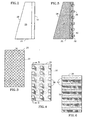
- FIG. 2, which is a simple schematic illustration of an elevator safety brake having a molybdenum alloy friction plate applied to the rail facing surface of the shoe base;
- FIG. 3, which is a simple schematic illustration of the embodiment of FIG. 2 further including a cross hatch pattern machined therein;
- FIG. 4, which is a simple schematic illustration of a further preferred embodiment of the present invention showing a plurality of molybdenum alloy friction tiles attached to the rail facing surface of the shoe base;
- FIG. 5, which is a simple cross-sectional view of the embodiment illustrated in FIG. 4, taken along the line 5-5 to illustrate the attachment of the friction tiles via a compliant material;
- FIG. 6, which is a simple schematic illustration of another preferred embodiment in which the molybdenum alloy friction material is attached to the base of the brake shoe in the form of a plurality of pins;
- FIG. 7, which is a simple cutaway schematic illustration of yet a further preferred embodiment in which the molybdenum alloy friction material is attached to the base of the brake shoe in the form of a plurality of buttons held by a plate; and
- FIG. 8, which is a simple isometric view of a button.
-
- FIG. 1 provides a simplified schematic illustration of a known elevator safety brake system upon which the present invention may be used. The
brake system 10 comprises a pair ofactuators 12 which are attached to anelevator car 14 and positioned in an opposing relationship about aguide rail 16 supported in an elevator hoistway (not shown). Theactuators 12 are formed, in part, by a wedge shapedguide shoe 18 which is movable withinhousing 20 in a direction which is generally perpendicular to theguide rail 16. Theguide shoe 18 is biased towards theguide rail 16 byspring 22. Theguide shoe 18 has aninclined support surface 24. A wedge shapedbrake shoe 25 havingbase 26 is provided with an inclined guidingsurface 28 which is complimentary to theinclined support surface 24 of theguide shoe 18. Thebrake shoe 25 is also provided with arail facing surface 30. Thebrake shoe 25 is positioned between theguide shoe 18 and therail 16. Abrake pad 32 having a high friction material is attached to therail facing surface 30 of thebrake shoe base 26. A roller cage assembly containing a plurality ofrollers 34 is positioned between theinclined support surface 24 of theguide shoe 18 and the complimentary inclined guideshoe facing surface 28 of thebrake shoe 25. Therollers 34 provide a low friction contact between the complimentary inclinedadjacent surfaces guide shoe 18 and thebrake shoe 25, respectively. Theguide shoe 18, biased byspring 22, applies normal force FN in the direction of therail 16 onbrake shoe 25 throughrollers 34. - In an emergency situation wherein the application of the
brake system 10 is desired, a force FA in the direction of theelevator car 14 is applied to thebase 26 of the wedgeshaped brake shoes 25 which causes theshoes 25 to move towards theelevator car 14. Ordinarily, force FA is supplied by a rope, cable or mechanical linkage connected to a governor (not shown). The inclinedcomplimentary surfaces guide shoe 18 and thebrake shoe base 26, respectively, cause thebrake shoe 25 to move towards therail 16 until contact between thepad 32 and therail 16 is made. As those skilled in the art will appreciate, thepad 32 is applied to therail 16 with normal force FN supplied by thespring 22. The amount of braking force developed by normal force FN is substantially and directly proportional to the friction coefficient µk between the high friction material used in thebrake pad 32 and therail material 16. As braking occurs, heat tends to become accumulated in thebrake pad 32 which can deleteriously alter the friction coefficient µk between the pad material and rail material. If the heat becomes high enough for a given material, a substantial reduction in the hardness, as well as deformation or fusion of the high friction material may occur, which in turn may cause brake failure. - In the prior art, the
brake pad 32 used in thebrake system 10 to provide a friction surface has been formed from gray cast iron. Gray cast iron, while suitable for low speed, low load conditions, cannot operate as a consistent friction material at high speed and load conditions. In view of the short comings of gray cast iron in such applications, it has been found that the gray cast iron material used as the high friction material inpads 32 may be replaced with a molybdenum alloy material. A brake pad having a molybdenum alloy material according to the present invention, which will be described more fully below, is capable of operation under the conditions required for an elevator operating at contract speeds of up to 10 meters per second with a load rating of up to 16000 Kg. It has been further found that the pads made in accordance with the present invention have significant mechanical toughness, thermal shock resistance, negligible wear rates on rail steel and appreciable coefficient of friction on rail steel. - A 30 mm diameter plate formed from TZM molybdenum alloy No. 364 conforming to ASTM standard B 387 - 90 containing approximately 99.4 weight percent molybdenum, 0.5 weight percent titanium and 0.1 weight percent zirconium was attached to a steel substrate to form a 30 mm diameter test tile and the edges of the molybdenum alloy material were provided with a chamfer. The test tile was loaded with a normal force of 11,000 N against a rotating 2 meter diameter disk under conditions which were selected to simulate an emergency stop on a typical steel hoistway guide rail surface under high load and high velocity conditions. A frictional force of nearly 6,000 N was generated which indicates that the material had a nominal coefficient of friction with the rail steel of about 0.40 which is about 1.5 times that of typical gray
cast iron grade 30. The TZM molybdenum alloy tile showed very little wear, about 1 percent of the wear exhibited by the typical graycast iron grade 30. The rail damage caused by the molybdenum alloy was equivalent to the damage caused bygrade 30 cast iron. The material performed adequately under all rail conditions simulated (clean rail, rusted rail, oiled rail, wet rail and roughened rail). - As illustrated in FIG 2., the friction surface of the brake may be in the form of a
plate 34 which is attached to thebase 26. As illustrated in FIG. 3, across hatch pattern 36 may be machined therein to provide a topography to the friction surface. Referring to FIGS. 4 and 5, alternatively, the friction surface may be formed from a plurality oftiles 38 of the TZM alloy material. Thetiles 38 may be attached to thebase 26 directly via mechanical fasteners (not shown) or alternatively, the tiles may be attached to thebase 26 via acompliant material interface 40 which enables resilient movement of the alloy friction material relative to thebase 26 and allows a greater number of tiles to make contact with the rail surface in the event that the rail facing surface of thebrake shoe base 26 is not perfectly true with therail 16. Compliant material which may be used in such preferred embodiments includes heat resistant rubber like material such as heat resistant silcone. Like thesingle plate 34, one or more of thetiles 40 may be provided with a cross hatch pattern machined therein (not shown). - Referring to FIG. 6, the friction surface may also be formed from a plurality of
pins 42 of the alloy material which are positioned so as to be generally transverse to the direction of relative movement between the friction surface and the guide rail surface. In most cases, thesepins 42 are oriented horizontally in a elevator system, however, they need not be. Thepins 42 may be attached to thebase 26 via a compliant material interface in the manner shown for attachment of thetiles 38. The compliant material interface enables resilient movement of thepins 42 relative to thebase 26. - Referring to FIGS. 7 and 8, in still yet another embodiment, the friction surface may be formed from a plurality of
buttons 46 of the alloy material having ahead 48 and astem 50. Each of theheads 48 of the plurality ofbuttons 46 are held adjacent to thebase 26 by afastening plate 52 having a plurality ofopenings 54 wherein the plurality of stems 50 project therethrough. - As will be understood from the foregoing description, according to the present invention, several embodiments of a safety brake system for stopping an elevator have been described. The molybdenum alloy employed therein provides a high coefficient of friction which is advantageous in that lower normal forces and smaller, lighter springs and safeties can be employed. It is to be understood that the embodiments described herein are merely illustrative of the principles of the invention. Various modifications may be made thereto by persons skilled in the art which will embody the principles of the invention and fall within the scope of the invention. Hence, the present invention is deemed limited only by the appended claims and the reasonable interpretation thereof.
Claims (11)
- An elevator safety brake for stopping an elevator car, the brake comprising:a brake shoe (25) having a base (26) and further having a friction surface (32) attached to the base for contacting an elevator guide rail surface (16), the brake further comprising means (12) for pressing the friction material of the brake shoe against the guide rail surface to stop the elevator car, and wherein at least a portion (32;38;42;46) of the friction surface comprises a molybdenum alloy material characterised in that said molybdenum alloy material is formed from approximately 99.4 weight percent molybdenum, 0.5 weight percent titanium and 0.1 weight percent zirconium.
- The brake of claim 1, wherein the friction surface is a plate (32) of the alloy material attached to the base.
- The brake of claim 2, wherein the plate contains a cross hatch pattern (36) machined therein.
- The brake of claim 1, wherein the friction surface comprises a plurality of tiles (38) of the alloy material.
- The brake of claim 4, wherein at least one of the tiles contains a cross hatch pattern (36) machined therein.
- The brake of claim 4 or 5, wherein at least one of the tiles (38) is attached to the base (26) via a compliant material (40) which enables resilient movement of the tile relative to the base.
- The brake of claim 6, wherein the compliant material (40) is a heat resistant rubber material.
- The brake of claim 1, wherein the friction surface comprises a plurality of pins of the alloy material and wherein the plurality of pins (42) are positioned so as to be substantially transverse to the direction of relative movement between the friction surface and the guide rail surface (16).
- The brake of claim 8, wherein at least one of the pins (42) is attached to the base (26) via a compliant material (40) which enables resilient movement of the pin relative to the base.
- The brake of claim 9, wherein the compliant material (40) is a heat resistant rubber material.
- The brake of claim 1, wherein the friction surface comprises a plurality of buttons (40) of the alloy material having a head (48) and a stem (50), and wherein the heads of the plurality of buttons are held adjacent to the base by a fastening plate (52) having a plurality of openings (54) wherein the plurality of stems project therethrough.
Applications Claiming Priority (2)
| Application Number | Priority Date | Filing Date | Title |
|---|---|---|---|
| US08/965,180 US6371261B1 (en) | 1997-11-06 | 1997-11-06 | Molybdenum alloy elevator safety brakes |
| US965180 | 1997-11-06 |
Publications (2)
| Publication Number | Publication Date |
|---|---|
| EP0921332A1 EP0921332A1 (en) | 1999-06-09 |
| EP0921332B1 true EP0921332B1 (en) | 2004-02-18 |
Family
ID=25509585
Family Applications (1)
| Application Number | Title | Priority Date | Filing Date |
|---|---|---|---|
| EP98309034A Expired - Lifetime EP0921332B1 (en) | 1997-11-06 | 1998-11-04 | Molybdenum alloy elevator safety brakes |
Country Status (6)
| Country | Link |
|---|---|
| US (1) | US6371261B1 (en) |
| EP (1) | EP0921332B1 (en) |
| JP (1) | JP4380819B2 (en) |
| CN (1) | CN1127446C (en) |
| DE (1) | DE69821729T2 (en) |
| MY (1) | MY123947A (en) |
Cited By (1)
| Publication number | Priority date | Publication date | Assignee | Title |
|---|---|---|---|---|
| WO2014200122A1 (en) * | 2013-06-10 | 2014-12-18 | Son Jae Ok | Constant operation type safety brake device for elevator |
Families Citing this family (39)
| Publication number | Priority date | Publication date | Assignee | Title |
|---|---|---|---|---|
| WO2003008317A1 (en) * | 2001-06-29 | 2003-01-30 | Mitsubishi Denki Kabushiki Kaisha | Emergency brake device of elevator |
| JP2004211888A (en) * | 2002-12-24 | 2004-07-29 | Inventio Ag | Brake-shoe for braking cable |
| DE10319082B3 (en) * | 2003-04-28 | 2004-12-16 | Estop Gmbh | Electromechanical brake for rotary components has actuator arrangement with separately controllable actuators, each associated with frictional element moved along wedge surface to press on braked part |
| KR100951518B1 (en) * | 2003-10-07 | 2010-04-07 | 오티스 엘리베이터 컴파니 | Emergency stop for ropeless elevators with remote reset |
| US20050145449A1 (en) * | 2003-12-29 | 2005-07-07 | Jelley Frederick A. | Gain stabilizing self-energized brake mechanism |
| CN1789102B (en) * | 2004-12-17 | 2010-12-08 | 中国建筑科学研究院建筑机械化研究分院 | Elevator overspeed protecting device |
| US20070240941A1 (en) * | 2005-12-21 | 2007-10-18 | Daniel Fischer | Brake shoe for use in elevator safety gear |
| JP4797786B2 (en) * | 2006-05-15 | 2011-10-19 | 株式会社日立製作所 | Elevator emergency stop device and elevator |
| MY143851A (en) * | 2006-12-05 | 2011-07-15 | Inventio Ag | Braking device for holding and braking a lift cabin in a lift facility |
| EP1930280A1 (en) * | 2006-12-07 | 2008-06-11 | Inventio Ag | Braking device and guide rail for an elevator with wedge-shaped braking surface |
| JP4561778B2 (en) * | 2007-06-04 | 2010-10-13 | 株式会社日立製作所 | Elevator emergency stop device |
| JP5244878B2 (en) * | 2010-09-24 | 2013-07-24 | 株式会社日立製作所 | Emergency stop device and elevator using the same |
| US9068609B2 (en) * | 2011-04-04 | 2015-06-30 | Dematic Systems Gmbh | Aisle emergency brake for rail-guided vehicle |
| BR112013024797A2 (en) * | 2011-05-30 | 2016-12-20 | Inventio Ag | controllable lift brake |
| BR112015001696A2 (en) * | 2012-08-02 | 2017-07-04 | Mitsubishi Electric Corp | elevator emergency stop device |
| WO2014035382A1 (en) * | 2012-08-29 | 2014-03-06 | Otis Elevator Company | Friction brake assembly with an abradable metal foam brake pad |
| EP2711504A1 (en) * | 2012-09-19 | 2014-03-26 | Siemens Aktiengesellschaft | Device for bridging a gap |
| JP6129662B2 (en) * | 2013-07-03 | 2017-05-17 | 株式会社日立製作所 | Emergency stop device and elevator |
| ES2710200T3 (en) * | 2013-11-15 | 2019-04-23 | Inventio Ag | Retention device for an elevator |
| SE538974C2 (en) * | 2013-12-03 | 2017-03-07 | Texo Application Ab | Emergency stop device for shuttles, and storage system with rails and shuttles |
| JP6807753B2 (en) * | 2014-06-12 | 2021-01-06 | オーチス エレベータ カンパニーOtis Elevator Company | Brake member drive mechanism |
| EP3154891B1 (en) * | 2014-06-12 | 2018-12-12 | Otis Elevator Company | Braking system resetting mechanism for a hoisted structure |
| US10071882B2 (en) * | 2014-11-19 | 2018-09-11 | Thyssenkrupp Ag | Elevator safety clamping jaw |
| CN107000994B (en) * | 2014-12-17 | 2020-10-09 | 因温特奥股份公司 | Buffer unit for elevator |
| DE202015102837U1 (en) * | 2015-06-01 | 2016-09-06 | Wittur Holding Gmbh | Elevator brake and / or safety gear with welded brake pad |
| US10486939B2 (en) | 2015-09-27 | 2019-11-26 | Otis Elevator Company | Breaking system for a hoisted structure and method of controlling braking a hoisted structure |
| WO2017098299A1 (en) * | 2015-12-07 | 2017-06-15 | Otis Elevator Company | Robust electrical safety actuation module |
| WO2017120235A1 (en) * | 2016-01-04 | 2017-07-13 | Otis Elevator Company | Molybdenum coated elevator safety brakes |
| CN107082336A (en) * | 2016-02-16 | 2017-08-22 | 上海三菱电梯有限公司 | Braking voussoir, emergency braking apparatus and the elevator of brake shoe for elevator emergency stop |
| CN108147254B (en) * | 2016-12-02 | 2020-12-01 | 奥的斯电梯公司 | Elevator system suspension member termination with improved pressure distribution |
| US10214385B2 (en) * | 2017-01-25 | 2019-02-26 | Otis Elevator Company | Elevator brake wedge |
| US11111105B2 (en) * | 2017-01-26 | 2021-09-07 | Otis Elevator Company | Compliant shear layer for elevator termination |
| CN107226406B (en) * | 2017-06-26 | 2018-09-21 | 杜辉 | A kind of anti-fall elevator |
| EP3549896A1 (en) * | 2018-04-06 | 2019-10-09 | KONE Corporation | Resetting device for resetting an actuator for actuating a safety gear of an elevator |
| EP3666713A1 (en) | 2018-12-13 | 2020-06-17 | Inventio AG | Brake shoe and safety brake device for a lift |
| EP3674248B1 (en) * | 2018-12-31 | 2022-09-07 | KONE Corporation | An elevator car parking brake |
| EP3725725B1 (en) * | 2019-04-17 | 2022-02-09 | KONE Corporation | Rope gripping member of a hoisting apparatus, rope gripping device, terminal arrangement and hoisting apparatus |
| EP3733584A1 (en) * | 2019-05-03 | 2020-11-04 | Otis Elevator Company | Combined safety brake and safety actuation mechanism |
| AT17380U1 (en) * | 2021-02-10 | 2022-02-15 | Plansee Se | BRAKE DISC FOR A DISC BRAKE |
Family Cites Families (20)
| Publication number | Priority date | Publication date | Assignee | Title |
|---|---|---|---|---|
| US2678271A (en) | 1951-10-06 | 1954-05-11 | Climax Molybdenum Co | Molybdenum-zirconium alloys |
| US2713923A (en) * | 1952-12-08 | 1955-07-26 | Budd Co | Brake shoe lining for de-icing brake surfaces |
| FR1115557A (en) * | 1954-05-26 | 1956-04-26 | Rech Etudes Production Sarl | Brake and clutch linings |
| GB805638A (en) * | 1955-12-22 | 1958-12-10 | Hubert H P Trist & Company Ltd | Improvements in and relating to friction or bearing members |
| US2960403A (en) | 1958-02-24 | 1960-11-15 | American Metal Climax Inc | Molybdenum-base alloys |
| US4146654A (en) | 1967-10-11 | 1979-03-27 | Centre National De La Recherche Scientifique | Process for making linings for friction operated apparatus |
| US3897582A (en) | 1970-08-21 | 1975-07-29 | Atlantic Res Corp | Braking elements |
| US3841949A (en) * | 1972-10-25 | 1974-10-15 | Twin Disc Inc | Composite friction plate |
| US3871934A (en) * | 1973-06-28 | 1975-03-18 | Carborundum Co | Resurfacing brake discs |
| GB1560042A (en) | 1976-07-23 | 1980-01-30 | Komori Seisakusho Co | Composite friction elements |
| FR2438201A1 (en) | 1978-10-03 | 1980-04-30 | Ferodo Sa | PROCESS FOR IMPROVING FRICTION CONDITIONS BETWEEN TWO ANTAGONIST FRICTION ORGANS, AND CORRESPONDING FRICTION ORGANS |
| JPS6411938A (en) * | 1987-07-07 | 1989-01-17 | Toshiba Corp | Molybdenum giant grain or single crystal and its production |
| US5163526A (en) | 1989-04-04 | 1992-11-17 | Zaporozhsky Avtomobilny Zavod "Kommunar" (Proizvodstvennoe Obiedinenie "AvtoZAZ") | Friction element of friction pair |
| JP2847530B2 (en) * | 1989-07-05 | 1999-01-20 | 財団法人 鉄道総合技術研究所 | Sliding show for magnetically levitated vehicles |
| GB2261480B (en) * | 1991-11-15 | 1995-05-17 | Ferodo Ltd | Brakes |
| KR0130481B1 (en) | 1993-02-03 | 1998-04-10 | 가나이 쯔도무 | Emergency stop equipment & elevator |
| JP2803974B2 (en) | 1993-07-30 | 1998-09-24 | 三菱電機株式会社 | Elevator emergency stop device |
| JP3114045B2 (en) | 1994-03-16 | 2000-12-04 | 株式会社日立製作所 | Emergency stop device and elevator for elevator |
| AT401778B (en) * | 1994-08-01 | 1996-11-25 | Plansee Ag | USE OF MOLYBDENUM ALLOYS |
| US5819879A (en) * | 1997-11-06 | 1998-10-13 | Otis Elevator Company | Safety brake |
-
1997
- 1997-11-06 US US08/965,180 patent/US6371261B1/en not_active Expired - Lifetime
-
1998
- 1998-10-05 MY MYPI98004543A patent/MY123947A/en unknown
- 1998-10-16 JP JP29485898A patent/JP4380819B2/en not_active Expired - Lifetime
- 1998-11-04 EP EP98309034A patent/EP0921332B1/en not_active Expired - Lifetime
- 1998-11-04 DE DE69821729T patent/DE69821729T2/en not_active Expired - Lifetime
- 1998-11-05 CN CN98123153A patent/CN1127446C/en not_active Expired - Lifetime
Cited By (1)
| Publication number | Priority date | Publication date | Assignee | Title |
|---|---|---|---|---|
| WO2014200122A1 (en) * | 2013-06-10 | 2014-12-18 | Son Jae Ok | Constant operation type safety brake device for elevator |
Also Published As
| Publication number | Publication date |
|---|---|
| DE69821729D1 (en) | 2004-03-25 |
| US6371261B1 (en) | 2002-04-16 |
| MY123947A (en) | 2006-06-30 |
| CN1217288A (en) | 1999-05-26 |
| EP0921332A1 (en) | 1999-06-09 |
| JP4380819B2 (en) | 2009-12-09 |
| JPH11209024A (en) | 1999-08-03 |
| DE69821729T2 (en) | 2004-11-25 |
| HK1020036A1 (en) | 2000-03-10 |
| CN1127446C (en) | 2003-11-12 |
Similar Documents
| Publication | Publication Date | Title |
|---|---|---|
| US6371261B1 (en) | Molybdenum alloy elevator safety brakes | |
| US5979615A (en) | Carbon--carbon composite elevator safety brakes | |
| US5964322A (en) | Elevator safety brake having a plasma sprayed friction coating | |
| CA1220145A (en) | Progressive safety | |
| AU765263B2 (en) | Device and method for preventing vertical displacements and vertical vibrations of the load carrying means of vertical conveyors | |
| KR101450876B1 (en) | Method and Modernization Set for Functional Detection of Braking Device, Elevator Device, Braking Device | |
| AU646603B2 (en) | Double-sided safety gear | |
| CA2188152C (en) | Safety brake apparatus for an elevator car or counterweight | |
| US20150083533A1 (en) | Customized friction for brakes | |
| JPH11199159A (en) | Elevator safety brake | |
| AU2003271338B2 (en) | Brake shoe for braking a cable | |
| US20190011007A1 (en) | Molybdenum coated elevator safety brakes | |
| RU2465190C2 (en) | Brake shoe designed to be used in lift safety gear | |
| CA2435327A1 (en) | Elevator safety brake | |
| HK1020036B (en) | Molybdenum alloy elevator safety brakes | |
| WO1993018998A1 (en) | Safety gear for lift cars | |
| AU671440B2 (en) | Safety gear for lift cars | |
| Barkand | Application of a suspension rope brake to a single rope mine hoisting system | |
| HK40074623A (en) | Release unit for actuating an elevator brake device | |
| NZ286085A (en) | Safety gear for lift car, gib supports brake lining of specific sintered alloy of copper, tin and carbon |
Legal Events
| Date | Code | Title | Description |
|---|---|---|---|
| PUAI | Public reference made under article 153(3) epc to a published international application that has entered the european phase |
Free format text: ORIGINAL CODE: 0009012 |
|
| AK | Designated contracting states |
Kind code of ref document: A1 Designated state(s): DE FR GB |
|
| AX | Request for extension of the european patent |
Free format text: AL;LT;LV;MK;RO;SI |
|
| 17P | Request for examination filed |
Effective date: 19990706 |
|
| RIN1 | Information on inventor provided before grant (corrected) |
Inventor name: NGUYEN, DAT T. Inventor name: LE DOUX, JOSEPH A.L. Inventor name: LUSSIER, FRED J. Inventor name: LANG, MICHAEL C. Inventor name: MCKEE, DAVID W. Inventor name: MCCLUSKEY, PHILIP H Inventor name: BEALS, JAMES T. Inventor name: THOMPSON, MARK S. |
|
| AKX | Designation fees paid |
Free format text: DE FR GB |
|
| 17Q | First examination report despatched |
Effective date: 20020227 |
|
| GRAH | Despatch of communication of intention to grant a patent |
Free format text: ORIGINAL CODE: EPIDOS IGRA |
|
| GRAS | Grant fee paid |
Free format text: ORIGINAL CODE: EPIDOSNIGR3 |
|
| GRAA | (expected) grant |
Free format text: ORIGINAL CODE: 0009210 |
|
| AK | Designated contracting states |
Kind code of ref document: B1 Designated state(s): DE FR GB |
|
| REG | Reference to a national code |
Ref country code: GB Ref legal event code: FG4D |
|
| REF | Corresponds to: |
Ref document number: 69821729 Country of ref document: DE Date of ref document: 20040325 Kind code of ref document: P |
|
| ET | Fr: translation filed | ||
| PLBE | No opposition filed within time limit |
Free format text: ORIGINAL CODE: 0009261 |
|
| STAA | Information on the status of an ep patent application or granted ep patent |
Free format text: STATUS: NO OPPOSITION FILED WITHIN TIME LIMIT |
|
| 26N | No opposition filed |
Effective date: 20041119 |
|
| PGFP | Annual fee paid to national office [announced via postgrant information from national office to epo] |
Ref country code: DE Payment date: 20141029 Year of fee payment: 17 Ref country code: FR Payment date: 20141110 Year of fee payment: 17 |
|
| REG | Reference to a national code |
Ref country code: DE Ref legal event code: R119 Ref document number: 69821729 Country of ref document: DE |
|
| REG | Reference to a national code |
Ref country code: FR Ref legal event code: ST Effective date: 20160729 |
|
| PG25 | Lapsed in a contracting state [announced via postgrant information from national office to epo] |
Ref country code: DE Free format text: LAPSE BECAUSE OF NON-PAYMENT OF DUE FEES Effective date: 20160601 |
|
| PG25 | Lapsed in a contracting state [announced via postgrant information from national office to epo] |
Ref country code: FR Free format text: LAPSE BECAUSE OF NON-PAYMENT OF DUE FEES Effective date: 20151130 |
|
| PGFP | Annual fee paid to national office [announced via postgrant information from national office to epo] |
Ref country code: GB Payment date: 20171020 Year of fee payment: 20 |
|
| REG | Reference to a national code |
Ref country code: GB Ref legal event code: PE20 Expiry date: 20181103 |
|
| PG25 | Lapsed in a contracting state [announced via postgrant information from national office to epo] |
Ref country code: GB Free format text: LAPSE BECAUSE OF EXPIRATION OF PROTECTION Effective date: 20181103 |