EP0920599B1 - Messen von Effekten des Brechungsindex eines Gases mit unterschiedlicher Vielfach - Interferometrie ( superheterodyn ) - Google Patents
Messen von Effekten des Brechungsindex eines Gases mit unterschiedlicher Vielfach - Interferometrie ( superheterodyn )Info
- Publication number
- EP0920599B1 EP0920599B1 EP97938284A EP97938284A EP0920599B1 EP 0920599 B1 EP0920599 B1 EP 0920599B1 EP 97938284 A EP97938284 A EP 97938284A EP 97938284 A EP97938284 A EP 97938284A EP 0920599 B1 EP0920599 B1 EP 0920599B1
- Authority
- EP
- European Patent Office
- Prior art keywords
- measurement
- beams
- wavelengths
- phase
- leg
- Prior art date
- Legal status (The legal status is an assumption and is not a legal conclusion. Google has not performed a legal analysis and makes no representation as to the accuracy of the status listed.)
- Expired - Lifetime
Links
- 230000000694 effects Effects 0.000 title claims description 10
- 238000005305 interferometry Methods 0.000 title description 17
- 238000005259 measurement Methods 0.000 claims description 96
- 230000010287 polarization Effects 0.000 claims description 56
- 238000000034 method Methods 0.000 claims description 43
- 230000003287 optical effect Effects 0.000 claims description 36
- 230000010363 phase shift Effects 0.000 claims description 22
- 230000010355 oscillation Effects 0.000 claims description 5
- 230000008859 change Effects 0.000 claims description 3
- 230000001427 coherent effect Effects 0.000 claims description 3
- 230000005855 radiation Effects 0.000 claims description 3
- 238000001514 detection method Methods 0.000 description 14
- 239000006185 dispersion Substances 0.000 description 13
- 238000012545 processing Methods 0.000 description 13
- 238000001393 microlithography Methods 0.000 description 9
- 239000013078 crystal Substances 0.000 description 8
- 238000006073 displacement reaction Methods 0.000 description 5
- 238000004364 calculation method Methods 0.000 description 4
- 238000004519 manufacturing process Methods 0.000 description 4
- 238000012937 correction Methods 0.000 description 3
- 230000001419 dependent effect Effects 0.000 description 3
- 238000004458 analytical method Methods 0.000 description 2
- 230000007812 deficiency Effects 0.000 description 2
- 230000006872 improvement Effects 0.000 description 2
- 238000004556 laser interferometry Methods 0.000 description 2
- 230000035559 beat frequency Effects 0.000 description 1
- 230000002939 deleterious effect Effects 0.000 description 1
- 238000010586 diagram Methods 0.000 description 1
- 238000005516 engineering process Methods 0.000 description 1
- 238000002474 experimental method Methods 0.000 description 1
- 239000000835 fiber Substances 0.000 description 1
- 238000001914 filtration Methods 0.000 description 1
- 239000000203 mixture Substances 0.000 description 1
- 238000012986 modification Methods 0.000 description 1
- 230000004048 modification Effects 0.000 description 1
- 238000007781 pre-processing Methods 0.000 description 1
- 230000008569 process Effects 0.000 description 1
- 230000009897 systematic effect Effects 0.000 description 1
- 238000012360 testing method Methods 0.000 description 1
- 230000036962 time dependent Effects 0.000 description 1
Images


Classifications
-
- G—PHYSICS
- G01—MEASURING; TESTING
- G01J—MEASUREMENT OF INTENSITY, VELOCITY, SPECTRAL CONTENT, POLARISATION, PHASE OR PULSE CHARACTERISTICS OF INFRARED, VISIBLE OR ULTRAVIOLET LIGHT; COLORIMETRY; RADIATION PYROMETRY
- G01J9/00—Measuring optical phase difference; Determining degree of coherence; Measuring optical wavelength
- G01J9/02—Measuring optical phase difference; Determining degree of coherence; Measuring optical wavelength by interferometric methods
Definitions
- the present invention relates to optical instruments for measuring distance and refractive index.
- the invention relates in particular to interferometric distance measurement independent of fluctuations in the refractive index of a gas in a measurement path.
- a frequently-encountered problem in metrology is the measurement of the refractive index of a column of air.
- heterodyne methods of phase estimation in which the phase varies with time in a controlled way.
- the source emits two orthogonal polarizations having slightly different optical frequencies (e.g. 2MHz).
- the interferometric receiver in this case is typically comprised of a linear potarizer and a photodetector to measure the time-varying interference signal.
- the signal oscillates at the beat frequency, and the phase of the signal corresponds to the relative phase difference.
- these known forms of interferometric metrology are limited by fluctuations in refractive index, and by themselves are unsuited to the next generation of microlithography instruments.
- the system of Dandliker et al. employs laser beams of two wavelengths, each of said beams comprising two polarization components separated in frequency by means of acousto-optic modulation. After passing these beams collinearly through a Michelson interferometer, the polarization components are mixed, resulting in a heterodyne signal.
- the heterodyne signal has a different frequency for each of the two wavelengths, therefrom results a so-called super-heterodyne signal, having a frequency equal to the difference in the heterodyne frequencies, and a phase associated with an equivalent wavelength equal to the product of the two laser wavelengths divided by the difference of the two wavelengths.
- the basic principle may be understood as follows. Interferometers and laser radar measure the optical path length between a reference and an object, most often in open air.
- the optical path length is the integrated product of the refractive index and the physical path traversed by the measurement beam.
- the refractive index varies with wavelength, but the physical path is independent of wavelength, it is generally possible to separate the physical path length from the fluctuations in refractive index, provided that the instrument employs at least two wavelengths.
- the variation of index with wavelength is known in the art as dispersion, therefore this technique will be referred to hereinafter as the dispersion technique.
- the dispersion technique for index measurement has a long history, and predates the introduction of the laser.
- An article entitled “Long-path interferometry through an uncontrolled atmosphere,” by K. E. Erickson (J. Opt. Soc. Am. 52 (7), 781-787 (1962)) describes the basic principles and provides an analysis of the feasibility of the technique for geophysical measurements. Additional theoretical proposals are found in an article entitled “Correction of optical distance measurements for the fluctuating atmospheric index of refraction,” by P. L. Bender and J. C. Owens (J. Geo. Res. 70 (10), 2461-2462 (1965)).
- phase detection means which employ simple homodyne quadrature detection, are insufficient for high resolution phase measurement.
- phase detection and signal processing means are not suitable for dynamic measurements, in which the motion of the object results in rapid variations in phase that are difficult to detect accurately.
- Prior-art heterodyne and superheterodyne interferometers are limited in accuracy by fluctuations in the refractive index of air
- Prior-art dispersion techniques for measuring index fluctuations require extremely high accuracy in interference phase measurement, typically exceeding by an order of magnitude the typical accuracy of high-precision distance-measuring interferometers
- Obvious modifications to prior-art interferometers to improve phase-measuring accuracy would increase the measurement time to an extent incompatible with the rapidity of stage motion in modem microlithography equipment
- Prior-art dispersion techniques require at least two extremely stable laser sources, or a single source emitting multiple, phase-locked wavelengths
- Prior-art dispersion techniques in microlithography applications are sensitive to stage motion during the measurement, resulting
- an apparatus for measuring fluctuations in the refractive index of a gas in a measurement path comprising: a source of at least two light beams having different wavelengths and a substantially harmonic relationship, the light beams each having orthogonal polarization states, means for introducing a frequency difference between the orthogonal polarization states of each of the light beams; means for aligning the light beams so that they pass through the same measurement path, optical means for producing phase shifted beams, the optical means comprising means for generating multiple passes over the measurement path for the light beams.
- the apparatus of the invention is characterized in that the number of passes for the respective light beams are harmonically related in a relationship which is substantially the same as the substantially harmonic relationship between the wavelengths, the phase shifts of the optically produced beams having a magnitude proportional to the product of the number of passes over the measurement path, of the physical length of the measurement path and the indices of refraction of the gas in the measurement path, and means for mixing the polarization components of each of the phase shifted beams for producing mixed output beams; means for producing heterodyne electrical signals from the intensities of the mixed output beams which comprise oscillations at heterodyne frequencies related to the frequency differences between the polarization states of the light beams and comprising heterodyne phases.
- the apparatus is also characterized by means for mixing at least two of the heterodyne electrical signals for producing at least one superheterodyne electrical signal comprising an amplitude modulated carrier having a superheterodyne modulation frequency substantially equal to half the difference of the two corresponding heterodyne frequencies and a superheterodyne modulation phase substantially equal to half the difference between the two corresponding heterodyne phases; and means for analyzing the superheterodyne modulation phase for determining the fluctuations in the refractive index over the measurement path.
- This apparatus (and the method defined below) are useful for distance measuring interferometry independent of the aforementioned fluctuations.
- the method for measuring fluctuations in the refractive index of a gas in a measurement path comprising the step of providing source light beams having source wavelengths which are substantially harmonically related to each other.
- the method of the invention is characterized by passing the beams through a combination of multiple passes through the same measurement path, providing heterodyne phase shifts based on the source wavelengths, the number of passes comprising each multiple pass being similarly harmonically related to the harmonically related source wavelengths for providing a superheterodyne modulation phase substantially insensitive to motion along said measurement path.
- the present invention provides a superheterodyne modulation phase that is substantially insensitive to stage motion.
- the superheterodyne modulation phase is a direct measure of fluctuations in the refractive index of air. Since the superheterodyne modulation frequency may be adjusted to any convenient value, the phase-measurement accuracy for compensating index fluctuations may be appropriately enhanced.
- An alternative embodiment of the invention includes the ability to compensate for unexpected fluctuations in the source wavelength, using additional monitor interferometer means and substantially the same electronic processing means as are employed in the primary apparatus.
- the monitor interferometer preferably comprises a fixed monitor path length having a carefully controlled refractive index, so that any measured variations in the monitor are attributable to and provide a measure of the wavelength stability.
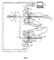
- FIG. 1 there is shown a preferred embodiment of the inventive apparatus of the present invention for measuring fluctuations in the refractive index of a gas in a measurement path 66. such as is useful for measuring the displacement of an object 67 independent of said fluctuations.
- a light beam 11 emitted from a source 1 passes through a modulator 2 excited by a driver 3.
- Source 1 is preferably a laser or like source of coherent radiation, preferably polarized, and having a wavelength ⁇ 1 .
- Modulator 2 may for example be an acousto-optic device or a combination of an acousto-optic device with additional optics for selectively modulating polarization components of beam 11.
- Modulator 2 preferably shifts the oscillation frequency of one linear polarization component of beam 11 an amount f 1 with respect to an orthogonal linear polarization component, said polarization components being denoted herein as x and y direction components, respectively. Therefore, after passing through modulator 2, the x polarization component of beam 11 has an oscillation frequency shifted upwards an amount f 1 with respect to the y polarization component of beam 11.
- a light beam 12 emitted from a source 4 passes through a modulator 5 excited by a driver 6, similar to modulator 2 and driver 3, respectively.
- Source 4 similarly to source 1 , is preferably a laser or like source of polarized, coherent radiation, but preferably at a different wavelength, ⁇ 2 , having a known approximate harmonic relationship with respect to ⁇ 1 , i.e. p 1 ⁇ 2 ⁇ p 2 ⁇ 1 for p 1 , p 2 ⁇ 1, 2, 3, ... p 1 ⁇ p 2
- the x polarization component of beam 12 has an oscillation frequency shifted upwards an amount f 2 with respect to the y polarization component of beam 12.
- beams 11 and 12 may be provided alternatively by a single laser source emitting more than one wavelength, or by a single laser source combined with optical frequency doubling means, or any equivalent source configuration capable of generating light beams of two or more wavelengths. It will also be appreciated by those skilled in the art that one or both of the frequency shifts f 1 , f 2 may be the result of Zeeman splitting or like phenomena characteristic of the laser sources themselves.
- beams 11 and 12 propagate to an interferometer 60, comprised of optical means for a introducing a phase shift ⁇ 1 between the x and y polarization components of beam 11 corresponding to wavelength ⁇ 1 and a phase shift ⁇ 2 between the x and y polarization components of beam 12 corresponding to wavelength ⁇ 2 .
- phase offsets ⁇ j comprise all contributions to the phase shifts ⁇ j that are not related to the measurement path 66.
- coefficients p 1 , p 2 are preferably identical to the like-denoted coefficients p 1 , p 2 used to define the approximate harmonic relationship in Eq. (1).
- interferometer 60 is comprised of a reference mirror 65, a quarter-wave plate 81, a quarter-wave plate 83, a polarizing beam splitter 23 and object 67 connected to a motion stage 68, or the like, by which object 67 may be moved to alter measurement path 66.
- This configuration is known in the art as a polarized Michelson interferometer, and is shown as a simple illustration.
- An angle-compensating interferometer or similar device such as is described in an article entitled Differential interferometer arrangements for distance and angle measurements: Principles, advantages and applications," by C. Zanoni (VDI Berichte Nr. 749, p.
- interferometer 60 An unusual and inventive characteristic of interferometer 60 is that beam 11 of wavelength ⁇ 1 experiences a phase shift ⁇ 1 proportional to the round-trip physical length L of measurement path 66 times the index of refraction n 1 , whereas beam 12 of wavelength ⁇ 2 experiences a phase shift ⁇ 2 proportional to twice the round-trip physical length L of measurement path 66 times the index of refraction n 2 . Beam 12, therefore, experiences a double pass through measurement path 66. Double-pass interferometers are known in the art as a means of improving measurement resolution, for example, as described in an article entitled "Double-passed two-beam interferometers" by P. Hariharan and D. Sen, J. Opt. Soc. Am.
- polarizing beam splitter 23 of interferometer 60 separates the two x and y polarization components of beams 11 and 12.
- Polarizing beam splitter 23 preferably reflects the x polarization components while transmitting the y polarization components. Therefore, x polarization component of beam 11 is directed as a beam 211 through quarter-wave plate 83, which converts the polarization state of beam 211 to circular. After reflection from reference mirror 65, quarter-wave plate 83 converts the polarization state of beam 211 back to linear, but the direction of polarization is now along the y direction.
- the y polarization component of beam 11 is directed as a beam 111 through quarter-wave plate 81, which converts the polarization state of beam 111 to circular.
- quarter-wave plate 81 converts the polarization state of beam 111 back to linear, but the direction of polarization is now along the x direction. Since beam 111 with the x polarization component is reflected and beam 211 with the y polarization component is transmitted by beam 23, both beams 111 and 211 combine to form a phase-shifted beam 15, which exits interferometer 60 as shown in Figure 1
- the x polarization component of beam 12 is directed as a beam 212 through quarter-wave plate 83, which converts the polarization state of beam 212 to circular.
- quarter-wave plate 83 converts the polarization state of beam 212 back to linear, but the direction of polarization is now along the y direction.
- the y polarization component of beam 12 is directed as a beam 112 through quarter-wave plate 81, which converts the polarization state of beam 112 to circular.
- quarter-wave plate 81 converts the polarization state of beam 112 back to linear, but the direction of polarization is now along the x direction.
- both beams 112 and 212 combine to form a beam 115, which propagates to folding prism 82, which redirects beam 115 back to polarizing beam splitter 23.
- Polarizing beam splitter 23 once again separates the polarization components of beam 115, this time creating a beam 113 having an x polarization state and a beam 213 having a y polarization state After passing twice through quarter-wave plate 83 and reflecting once from reference mirror 65, beam 213 is converted back to x polarization.
- beam 113 is converted back to y polarization. Since beam 213 with the x polarization component is reflected and beam 113 with the y polarization component is transmitted by beam splitter 23 both beams 213 and 113 combine to form a phase-shifted beam 16, which exits interferometer 60 as shown in Figure 1 after reflection from fold mirror 84.
- phase-shifted beams 15 and 16 shown in Figure 1 pass through a polarizer 44 preferably oriented so as to mix the x and y polarization components of each of beams 15 and 16.
- Heterodyne interference signals s 1 , s
- Superheterodyne signal S is therefore a carrier signal C of frequency V modulated by an envelope signal M of frequency F .
- heterodyne signals s 1 , s 2 are of different amplitude, the resulting mathematical expression is more complicated, but nonetheless may be described in terms of a carrier signal modulated by an envelope signal. For simplicity in the present disclosure, it is assumed that modified heterodyne signals s 1 , s 2 have the same amplitude.
- electronic processing means 98 preferably comprises a means 983 to separate envelope signal M from carrier signal C , using rectification and filtering, signal squaring, or any of the like techniques for extracting an amplitude modulation and demodulating a carrier.
- Electronic processing means 98 further comprises a means 985 to determine the modulation phase ⁇ using time-based phase detection or the like.
- Electronic processing means 98 additionally comprises a means 986 and a means 987 to determine the phases ⁇ 1 and ⁇ 2 , respectively.
- n 1 1 + A L ( K ⁇ - ⁇ - Q ).
- A 2 ⁇ ( ⁇ 2 - K 2 )
- Constant ⁇ is a measure of the dispersion of the refractive index of air.
- Q is considered a constant, or is monitored by purely electronic means (not shown).
- the superheterodyne modulation phase ⁇ is also only weakly dependent upon the distance L , relative to the very strong dependence of the carrier phase ⁇ and of the phase shifts ⁇ 1 , ⁇ 2 . This greatly improves the phase detection accuracy for moving objects, such as are commonly encountered in microlithography equipment.
- the inventive apparatus and means provides a convenient way of compensating for source wavelength instability as follows.
- This formula shows that the magnitude of the error is substantially independent of the object distance L , and of all other variables such as the phase shifts ⁇ 1 , ⁇ 2 that depend directly on the object distance L . It is therefore possible to compensate for the effects of wavelength stability by measuring the index of refraction along a monitor path that is entirely free of real fluctuations in index. Any measured variations are the result of wavelength instability.
- FIG 4 there is shown an alternative embodiment of the present invention in which a monitor system 60b has been added to the embodiment of Figure 1 for the purpose of compensating for an error ⁇ n 1 in refractive index measurement attributable to source wavelength instability.
- a beam splitter 70 and a mirror 71 reflect a portion of beams 11 and 12 towards monitor system 60b.
- Monitor system 60b comprises a number of elements performing analogous operations as interferometer 60, with elements performing like operations as like denoted elements as interferometer 60, apart from the suffix "b" when referring to elements of monitor system 60b.
- a monitor electronic processing system 98b similarly performs like operations as electronic processing system 98.
- monitor path 66b of monitor system 60b is preferably a fixed length, with a carefully controlled refractive index, such as may be achieved by enclosing monitor path 66b and controlling the temperature and pressure of the enclosed volume.
- refractive index along monitor path 86b is substantially constant, any measured variations ⁇ n M in the monitor system are attributable to source wavelength instability.
- This inventive compensation technique greatly reduces the wavelength stability requirements for the source. It is particularly noteworthy that the present invention does not require absolute wavelength stability, and a monitor path 66b need not have an extraordinarily stable physical length L .
- the present invention provides accurate measurement of and compensation for fluctuations in the refractive index of air, such as is useful for distance measuring interferometry; (2) the present invention is compatible with the rapid stage motion common to modem microlithography equipment; (3) the present invention optionally comprises easily-incorporated monitor means and method to substantially reduce source stability requirements; and (4) the apparatus of the present invention is substantially less complicated and expensive relative to comparable prior art.
- optical elements and electronic processing steps may be incorporated into one of the disclosed embodiments of the inventive apparatus.
- additional detectors and associated elements may be added to the embodiments to measure and compensate for the various phase offsets encountered in the data processing.
Claims (22)
- Vorrichtung zum Messen des Einflusses des Brechungsindexes eines Gases in einer Meßstrecke, mit:dadurch gekennzeichnet, dass zum Ausgleich der relativen zeitlichen Änderung der geometrischen Lichtwege der ersten (64) und zweiten (66) Meßschenkel Strahlen einer der Wellenlängen der ersten und zweiten vorgegebenen Anteile vorbestimmten Lichtwegen entlang durch mindestens einen der ersten (64) und zweiten (66) Meßschenkel mit einer sich von den Durchgängen der Strahlen der jeweils anderen Wellenlängen der ersten und zweiten vorgegebenen Anteile unterscheidenden Anzahl von Durchgängen geführt werden,einer Lichtquelle (1, 4) für mindestens zwei Lichtstrahlen (11, 12) unterschiedlicher Wellenlängen;einem Interferometer (60) aufweisend erste (64) und zweite (66) Meßschenkel, deren Lichtwege derart verlaufen, dass mindestens ein Schenkel (66) eine geometrisch variable Länge aufweist und mindestens ein Schenkel (66) mindestens teilweise vom Gas umgeben ist, während ein Schenkel (64) mindestens teilweise von einem vorbestimmten Medium umgeben sein kann, wobei der Lichtweg-Längenunterschied zwischen dem ersten (64) und dem zweiten (66) Meßschenkel in Abhängigkeit des physischen Längenunterschieds zwischen den Lichtwegen sowie der Eigenschaften des Gases und des vorbestimmten Mediums variiert;Einfügemitteln zum Einblenden erster und zweiter vorgegebener Anteile jedes der Lichtstrahlen (11, 12) in den ersten (64) bzw. zweiten (66) Meßschenkel, so dass die vorgegebenen ersten und zweiten Anteile unter Beinhaltung von Informationen über die jeweiligen Lichtweglängen durch den ersten (64) bzw. zweiten (66) Meßschenkel mit den Wellenlängen der ursprünglichen Strahlen (11, 12) als Ausgangsstrahlen (15, 16) aus dem Interferometer (60) austreten;Mischmitteln (44) zum Kombinieren der Ausgangsstrahlen (15, 16) zur Erzeugung optischer Mischsignale mit den der Phasendifferenz zwischen den Ausgangsstrahlen (15, 16) entsprechenden Informationen,
dass Erfassungsmittel (45, 46) vorgesehen sind zur Erkennung der optischen Mischsignale und Erzeugung elektrischer Interferenzsignale (s 1, s 2) mit Informationen über den Einfluss der Brechungsindizen des Gases und des vorbestimmten Mediums bei den verschiedenen Wellenlängen und relativen Streckenlängen der ersten (64) und zweiten (66) Meßschenkel sowie deren relativen zeitlichen Änderung; und
und dass elektronische Mittel (98) zur Auswertung der elektrischen Interferenzsignale (s 1,s 2) und Bestimmung des Einflusses des Gases in den Meßschenkeln (64, 66) vorgesehen sind. - Vorrichtung nach Anspruch 1, dadurch gekennzeichnet, dass die Lichtstrahlen (11, 12) Wellenlängen wesentlicher harmonischer Beziehung und diese Strahlen (11, 12) jeweils orthogonale Polarisationszustände aufweisen, dass die Anzahl der Durchgänge der jeweiligen Lichtstrahlen (11, 12, 111, 112) in einem weitgehend der wesentlichen harmonischen Beziehung zwischen den Wellenlängen der Strahlen (11, 12) entsprechenden wesentlichen harmonischen Verhältnis steht, und dass die Einfügemittel Mittel (2, 5) zur Erzeugung einer Frequenzdifferenz zwischen den orthogonalen Polarisationszuständen der einzelnen Lichtstrahlen (11, 12), Mittel zum Bündeln der Lichtstrahlen (11, 12) in einen gemeinsamen Meßschenkel (66) sowie optische Mittel zur Erzeugung mehrfacher Durchgänge der Lichtstrahlen (11, 12, 111, 112) durch den mindestens teilweise vom Gas umgebenen Meßschenkel (66) umschließen, wobei die Phasenänderungen der Ausgangsstrahlen (15, 16) größenmäßig proportional der Anzahl der Durchgänge durch den besagten Meßschenkel (66), der geometrischen Länge dieses Meßschenkels (66) und den Brechungsindizen des Gases in diesem Meßschenkel (66) entsprechen.
- Vorrichtung nach Anspruch 2, dadurch gekennzeichnet, dass die Mischmittel (44) durch Mischen der Polarisationskomponenten jedes der Ausgangsstrahlen (15, 16) zur Erzeugung gemischter Ausgangsstrahlen dienen, und dass die Erfassungsmittel (45, 46) aus den Intensitäten der gemischten Ausgangsstrahlen elektrische Überlagerungssignale (s 1, s 2) erzeugen, die den Frequenzdifferenzen zwischen den Polarisationszuständen der Lichtstrahlen entsprechende, überlagerte Phasen aufweisende Schwingungen überlagerter Frequenzen enthalten.
- Vorrichtung nach Anspruch 3, gekennzeichnet durch Mittel (982) zum Mischen von mindestens zwei der überlagerten elektrischen Signale (s 1, s 2) zur Erzeugung mindestens eines elektrischen Überlagerungssignals (S) mit einem amplitudenmodulierten Trägersignal (C) einer Überlagerungs-Modulationsfrequenz (F) , die im wesentlichen der halben Differenz der betreffenden beiden Überlagerungsfrequenzen entspricht, sowie mit einer Überlagerungs-Modulationsphase, die im wesentlichen der halben Differenz zwischen den beiden Überlagerungsphasen gleich ist; sowie Mittel (983, 985, 986, 987) zur Auswertung der Überlagerungs-Modulationsphase und Bestimmung der Schwankungen des Brechungsindexes entlang des Meßschenkels (66).
- Vorrichtung nach Anspruch 4, dadurch gekennzeichnet, dass jeder der Lichtstrahlen (11, 12) zwei orthogonale Polarisationszustände aufweist, wobei die die Frequenzdifferenz erzeugenden Mittel (2, 5) weitere Mittel zum Einfügen der Frequenzdifferenz zwischen die beiden orthogonalen Polarisationszustände jedes der Lichtstrahlen enthalten und diese Frequenzdifferenz für die mindestens zwei Strahlen unterschiedlich ist.
- Vorrichtung nach Anspruch 4 oder 5, dadurch gekennzeichnet, dass die Mittel zum Ausrichten der Lichtstrahlen optische Mittel zum Bündeln aller Lichtstrahlen zum Durchgang durch den gemeinsamen Messweg (66) umfassen.
- Vorrichtung nach einem der Ansprüche 4 bis 6, dadurch gekennzeichnet, dass die optischen Mittel zur Erzeugung der Ausgangsstrahlen (15, 16) weitere optische Mittel zur Phasenänderung zwischen den Polarisationszuständen jedes der Lichtstrahlen umfassen.
- Vorrichtung nach einem der vorhergehenden Ansprüche, dadurch gekennzeichnet, dass die Mittel (982) zum Mischen von mindestens zwei der überlagerten elektrischen Signale (s 1, s 2) weitere Mittel zum Mischen jeglicher zwei der besagten überlagerten elektrischen Signale (s 1, s 2) zur Erzeugung des besagten mindestens einen elektrischen Überlagerungssignals (S) mit dem amplituden-modulierten Träger (C) der überlagerten Modulationsfrequenz (F) umfassen.
- Vorrichtung nach einem der vorgehenden Ansprüche, dadurch gekennzeichnet, dass die Lichtquelle (1, 4) eine Quelle kohärenter Strahlung enthält.
- Vorrichtung nach einem der Ansprüche 4 bis 7, dadurch gekennzeichnet, dass die Mittel (982) zum Mischen der überlagerten Signale elektronischer Art sind.
- Vorrichtung nach einem der vorhergehenden Ansprüche, dadurch gekennzeichnet, dass die optischen Mittel zur Erzeugung der Ausgangsstrahlen (15, 16) ein Mehrfachdurchgangs-Interferometer umfassen.
- Vorrichtung nach einem der Ansprüche 4 bis 7 sowie 10, gekennzeichnet durch Mittel (60b) zum Ausgleich von auf Wellenlängenschwankungen der Lichtquelle (1, 4) beruhenden Fehlern der Überlagerungs-Modulationsphase.
- Vorrichtung nach Anspruch 12, dadurch gekennzeichnet, dass die Ausgleichsmittel (60b) ein Interferometer umfassen, dessen Meßstrecke einen Kontrollpfad (66b) fester Länge und ein Gas geregelten Brechungsindexes einbeschließt.
- Vorrichtung nach Anspruch 12 oder 13, dadurch gekennzeichnet, dass die Ausgleichsmittel (60b) weitere Mittel (45b, 46b) zur Erzeugung überlagerter Kontrollsignale umfassen.
- Vorrichtung nach einem der Ansprüche 12 bis 14, dadurch gekennzeichnet, dass die Ausgleichsmittel (60b) weitere Mittel (98b) zum Mischen jeglicher zwei elektrischer Überlagerungskontrollsignale zur Erzeugung mindestens eines elektrischen, einen amplitudenmodulierten Träger mit einer Überlagerungsmodulations-Kontrollfrequenz aufweisenden Überlagerungskontrollsignals umfassen.
- Verfahren zum Messen des Einflusses des Brechungsindexes eines Gases in einer Meßtrecke, unter:gekennzeichnet durch Strahlen einer der Wellenlängen der ersten und zweiten vorgegebenen Anteile, die zum Ausgleich der relativen zeitlichen Änderung der geometrischen Lichtwege der ersten (64) und zweiten (66) Meßschenkel vorbestimmten Lichtwegen entlang durch mindestens einen der ersten (64) und zweiten (66) Meßschenkel mit einer sich von den Durchgängen der Strahlen der jeweils anderen Wellenlängen der ersten und zweiten vorgegebenen Anteile unterscheidenden Anzahl von Durchgängen geführt werden,Bereitstellung von Lichtstrahlen (11, 12) unterschiedlicher Wellenlängen;Bereitstellung eines Interferometers (60) aufweisend erste (64) und zweite (66) Meßschenkel, deren Lichtwege derart verlaufen, dass mindestens ein Schenkel (66) eine geometrisch variable Länge aufweist und mindestens ein Schenkel (66) mindestens teilweise vom Gas umgeben ist und der andere Schenkel (64) mindestens teilweise von einem vorbestimmten Medium umgeben sein kann, wobei der Lichtweg-Längenunterschied zwischen dem ersten (64) und zweiten (66) Meßschenkel in Abhängigkeit vom physischen Längenunterschied zwischen den Lichtwegen sowie der Eigenschaften des Gases und des vorbestimmten Mediums variiert;Einfügen erster und zweiter vorgegebener Anteile jedes der Lichtstrahlen (11, 12) in den ersten (64) bzw. zweiten (66) Meßschenkel, so dass die ersten und zweiten vorgegebenen Anteile unter Beinhaltung von Informationen über die jeweiligen Lichtweglängen durch den ersten (64) bzw. zweiten (66) Meßschenkel mit den Wellenlängen der ursprünglichen Strahlen (11, 12) als Ausgangsstrahlen (15, 16) aus dem Interferometer (60) austreten;Zusammenlegung der Ausgangsstrahlen (15, 16) zur Erzeugung optischer Mischsignale mit den der Phasendifferenz zwischen den Ausgangsstrahlen (15, 16) entsprechenden Informationen,
Erfassung der optischen Mischsignale und Erzeugung elektrischer Interferenzsignale (s 1, s 2) mit Informationen über den Einfluss der Brechungsindizen des Gases und des vorbestimmten Mediums bei den verschiedenen Wellenlängen und relativen Streckenlängen der ersten (64) und zweiten (66) Meßschenkel sowie deren relativen zeitlichen Änderung; und
elektronischer Auswertung der elektrischen Interferenzsignale (s 1, s 2) zur Ermittlung des Gaseinflusses in den Meßschenkeln (64, 66). - Verfahren nach Anspruch 16, gekennzeichnet durch Lichtstrahlen (11, 12), deren Wellenlängen eine im wesentlichen harmonische Beziehung aufweisen, sowie durch die Erzeugung überlagerter Phasenänderungen auf Grundlage der Lichtquellenwellenlängen, wobei die Anzahl der Strahlendurchgänge bei jedem Mehrfachdurchgang jeweils in einem ähnlichen Oberwellenverhältnis zu den harmonisch bezogenen Wellenlängen steht, um eine weitgehend auf Bewegungen im mindestens teilweise vom Gas umgebenen Meßschenkel (66) unempfindliche überlagerte Modulationsphase zu erzeugen.
- Verfahren nach Anspruch 17, dadurch gekennzeichnet, dass der mindestens teilweise vom Gas umgebene Meßschenkel (66) eine Meßstrecke in einem Mehrfachdurchgangs-Interferometer (60) mit einer entlang dem Meßschenkel (66) verfahrbaren Bühne (67) umfasst, wobei aufgrund einer die überlagerte Modulationsphase erzeugenden Maßnahme die Überlagerungsmodulationsphase im wesentlichen gegen eine Bewegung der Bühne (67) im Messweg (66) unempfindlich ist.
- Verfahren nach Anspruch 17 oder 18, gekennzeichnet durch die Bestimmung einer Weglänge L entlang dem Meßschenkel (66) unabhängig von Schwankungen des Brechungsindexes n.
- Verfahren nach Anspruch 19, dadurch gekennzeichnet, dass die Ermittlung der Weglänge L gemäß der Gleichung
- Verfahren nach einem der Ansprüche 17 bis 20, dadurch gekennzeichnet, dass jeder der Lichtstrahlen (11, 12) einen orthogonalen Zustand aufweist, dass der Vorgang der Erzeugung überlagerter Phasenänderungen optisch phasenverschobene Strahlen (15, 16) einbeschließt, indem Phasenänderungen zwischen den Polarisationszuständen jedes der Lichtstrahlen vorgenommen werden, deren Phasenänderungsgröße sich proportional zur Anzahl der Strahlendurchgänge durch den Meßschenkel (66), umgekehrt proportional zur Wellenlänge des Lichtstrahls, proportional zur geometrischen Länge des Meßschenkels (66) und proportional zu den Brechungsindizen des Gases im Meßschenkel (66) verhält.
- Verfahren nach einem der Ansprüche 17 bis 21, gekennzeichnet durch den Ausgleich von durch Schwankungen der Quellwellenlängen in der Überlagerungsmodulationsphase verursachten Fehlern.
Applications Claiming Priority (5)
| Application Number | Priority Date | Filing Date | Title |
|---|---|---|---|
| US08/700,113 US5764362A (en) | 1996-08-20 | 1996-08-20 | Superheterodyne method and apparatus for measuring the refractive index of air using multiple-pass interferometry |
| US700113 | 1996-08-20 | ||
| DE19727402A DE19727402A1 (de) | 1996-08-20 | 1997-06-27 | Überlagerungsverfahren und Vorrichtung zur Messung des Brechungsindex von Luft unter Benutzung der Mehrfach-Interferometrie |
| DE19727402 | 1997-06-27 | ||
| PCT/US1997/014273 WO1998008047A1 (en) | 1996-08-20 | 1997-08-14 | Superheterodyne method and apparatus for measuring the refractive index of air using multiple-pass interferometry |
Publications (3)
| Publication Number | Publication Date |
|---|---|
| EP0920599A1 EP0920599A1 (de) | 1999-06-09 |
| EP0920599A4 EP0920599A4 (de) | 1999-11-17 |
| EP0920599B1 true EP0920599B1 (de) | 2003-10-29 |
Family
ID=26037794
Family Applications (1)
| Application Number | Title | Priority Date | Filing Date |
|---|---|---|---|
| EP97938284A Expired - Lifetime EP0920599B1 (de) | 1996-08-20 | 1997-08-14 | Messen von Effekten des Brechungsindex eines Gases mit unterschiedlicher Vielfach - Interferometrie ( superheterodyn ) |
Country Status (2)
| Country | Link |
|---|---|
| EP (1) | EP0920599B1 (de) |
| WO (1) | WO1998008047A1 (de) |
Families Citing this family (5)
| Publication number | Priority date | Publication date | Assignee | Title |
|---|---|---|---|---|
| EP1172698B1 (de) * | 2000-07-14 | 2006-02-08 | ASML Netherlands B.V. | Lithographischer Projektionsapparat, Verfahren zur Herstellung eines Artikel, dabei erzeugter Artikel und Gaszusammensetzung |
| GB2406903B (en) * | 2003-10-07 | 2006-11-22 | Interferomet Ltd | Method of and apparatus for use in determining refractive index |
| GB0919854D0 (en) | 2009-11-12 | 2009-12-30 | Stfc Science & Technology | Detecting species in a dilute medium |
| US9025163B2 (en) | 2011-04-22 | 2015-05-05 | The Trustess Of Princeton University | Chirp modulation-based detection of chirped laser molecular dispersion spectra |
| US9068940B2 (en) | 2012-10-19 | 2015-06-30 | The Trustees Of Princeton University | Optical subtraction of molecular dispersion signals enabled by differential optical dispersion spectroscopy |
Family Cites Families (1)
| Publication number | Priority date | Publication date | Assignee | Title |
|---|---|---|---|---|
| US5404222A (en) * | 1994-01-14 | 1995-04-04 | Sparta, Inc. | Interferametric measuring system with air turbulence compensation |
-
1997
- 1997-08-14 WO PCT/US1997/014273 patent/WO1998008047A1/en active IP Right Grant
- 1997-08-14 EP EP97938284A patent/EP0920599B1/de not_active Expired - Lifetime
Also Published As
| Publication number | Publication date |
|---|---|
| EP0920599A1 (de) | 1999-06-09 |
| EP0920599A4 (de) | 1999-11-17 |
| WO1998008047A1 (en) | 1998-02-26 |
Similar Documents
| Publication | Publication Date | Title |
|---|---|---|
| US5764362A (en) | Superheterodyne method and apparatus for measuring the refractive index of air using multiple-pass interferometry | |
| US5838485A (en) | Superheterodyne interferometer and method for compensating the refractive index of air using electronic frequency multiplication | |
| US6525825B2 (en) | Interferometer and method for measuring the refractive index and optical path length effects of air | |
| US6327039B1 (en) | Interferometer and method for measuring the refractive index and optical path length effects of air | |
| US6882432B2 (en) | Frequency transform phase shifting interferometry | |
| US6124931A (en) | Apparatus and methods for measuring intrinsic optical properties of a gas | |
| US6219144B1 (en) | Apparatus and method for measuring the refractive index and optical path length effects of air using multiple-pass interferometry | |
| US4693605A (en) | Differential plane mirror interferometer | |
| US4752133A (en) | Differential plane mirror interferometer | |
| JPH01503172A (ja) | 光学的ヘテロダイン処理を有する2波長のインターフェロメトリーのための方法および装置と位置または距離測定のための使用 | |
| US4802764A (en) | Differential plane mirror interferometer having beamsplitter/beam folder assembly | |
| EP0920600B1 (de) | Superheterodyn-interferometer und verfahren zur kompensation des brechungsindexes von luft mittels elektronischer frequenzmultiplikation | |
| EP0920599B1 (de) | Messen von Effekten des Brechungsindex eines Gases mit unterschiedlicher Vielfach - Interferometrie ( superheterodyn ) | |
| EP1066495B1 (de) | Verfahren und vorrichtung zum messen des einflusses der luft auf den brechungsindex und die optische weglänge mittels vielfachreflektions-interferometrie | |
| JP3626907B2 (ja) | 干渉測定方法および装置 | |
| EP1058810B1 (de) | Apparat und verfahren zum messen der intrinsischen optischen eigenschaften eines gases | |
| GB2391935A (en) | Compact non-linear interferometer with ultrahigh sensitivity |
Legal Events
| Date | Code | Title | Description |
|---|---|---|---|
| PUAI | Public reference made under article 153(3) epc to a published international application that has entered the european phase |
Free format text: ORIGINAL CODE: 0009012 |
|
| 17P | Request for examination filed |
Effective date: 19990127 |
|
| AK | Designated contracting states |
Kind code of ref document: A1 Designated state(s): DE NL |
|
| A4 | Supplementary search report drawn up and despatched |
Effective date: 19991004 |
|
| AK | Designated contracting states |
Kind code of ref document: A4 Designated state(s): DE NL |
|
| 17Q | First examination report despatched |
Effective date: 20010306 |
|
| GRAH | Despatch of communication of intention to grant a patent |
Free format text: ORIGINAL CODE: EPIDOS IGRA |
|
| RTI1 | Title (correction) |
Free format text: MEASURING THE EFFECTS OF THE REFRACTIVE INDEX OF A GAS USING DIFFERENT MULTIPLE PATH INTERFEROMETRY ( SUPERHETRODYNE ) |
|
| GRAH | Despatch of communication of intention to grant a patent |
Free format text: ORIGINAL CODE: EPIDOS IGRA |
|
| GRAA | (expected) grant |
Free format text: ORIGINAL CODE: 0009210 |
|
| AK | Designated contracting states |
Kind code of ref document: B1 Designated state(s): DE NL |
|
| REF | Corresponds to: |
Ref document number: 69725859 Country of ref document: DE Date of ref document: 20031204 Kind code of ref document: P |
|
| PLBE | No opposition filed within time limit |
Free format text: ORIGINAL CODE: 0009261 |
|
| STAA | Information on the status of an ep patent application or granted ep patent |
Free format text: STATUS: NO OPPOSITION FILED WITHIN TIME LIMIT |
|
| 26N | No opposition filed |
Effective date: 20040730 |
|
| PGFP | Annual fee paid to national office [announced via postgrant information from national office to epo] |
Ref country code: DE Payment date: 20081031 Year of fee payment: 12 |
|
| PG25 | Lapsed in a contracting state [announced via postgrant information from national office to epo] |
Ref country code: DE Free format text: LAPSE BECAUSE OF NON-PAYMENT OF DUE FEES Effective date: 20100302 |
|
| PGFP | Annual fee paid to national office [announced via postgrant information from national office to epo] |
Ref country code: NL Payment date: 20140826 Year of fee payment: 18 |
|
| REG | Reference to a national code |
Ref country code: NL Ref legal event code: MM Effective date: 20150901 |
|
| PG25 | Lapsed in a contracting state [announced via postgrant information from national office to epo] |
Ref country code: NL Free format text: LAPSE BECAUSE OF NON-PAYMENT OF DUE FEES Effective date: 20150901 |