EP0919712A2 - Steuersystem für eine funkgezündete Brennkraftmaschine mit Direkt-Einspritzung - Google Patents
Steuersystem für eine funkgezündete Brennkraftmaschine mit Direkt-Einspritzung Download PDFInfo
- Publication number
- EP0919712A2 EP0919712A2 EP98309718A EP98309718A EP0919712A2 EP 0919712 A2 EP0919712 A2 EP 0919712A2 EP 98309718 A EP98309718 A EP 98309718A EP 98309718 A EP98309718 A EP 98309718A EP 0919712 A2 EP0919712 A2 EP 0919712A2
- Authority
- EP
- European Patent Office
- Prior art keywords
- engine
- fuel
- injection
- control system
- suction stroke
- Prior art date
- Legal status (The legal status is an assumption and is not a legal conclusion. Google has not performed a legal analysis and makes no representation as to the accuracy of the status listed.)
- Granted
Links
Images


Classifications
-
- F—MECHANICAL ENGINEERING; LIGHTING; HEATING; WEAPONS; BLASTING
- F02—COMBUSTION ENGINES; HOT-GAS OR COMBUSTION-PRODUCT ENGINE PLANTS
- F02D—CONTROLLING COMBUSTION ENGINES
- F02D41/00—Electrical control of supply of combustible mixture or its constituents
- F02D41/30—Controlling fuel injection
- F02D41/3011—Controlling fuel injection according to or using specific or several modes of combustion
- F02D41/3017—Controlling fuel injection according to or using specific or several modes of combustion characterised by the mode(s) being used
- F02D41/3023—Controlling fuel injection according to or using specific or several modes of combustion characterised by the mode(s) being used a mode being the stratified charge spark-ignited mode
- F02D41/3029—Controlling fuel injection according to or using specific or several modes of combustion characterised by the mode(s) being used a mode being the stratified charge spark-ignited mode further comprising a homogeneous charge spark-ignited mode
-
- F—MECHANICAL ENGINEERING; LIGHTING; HEATING; WEAPONS; BLASTING
- F01—MACHINES OR ENGINES IN GENERAL; ENGINE PLANTS IN GENERAL; STEAM ENGINES
- F01N—GAS-FLOW SILENCERS OR EXHAUST APPARATUS FOR MACHINES OR ENGINES IN GENERAL; GAS-FLOW SILENCERS OR EXHAUST APPARATUS FOR INTERNAL COMBUSTION ENGINES
- F01N3/00—Exhaust or silencing apparatus having means for purifying, rendering innocuous, or otherwise treating exhaust
- F01N3/08—Exhaust or silencing apparatus having means for purifying, rendering innocuous, or otherwise treating exhaust for rendering innocuous
- F01N3/0807—Exhaust or silencing apparatus having means for purifying, rendering innocuous, or otherwise treating exhaust for rendering innocuous by using absorbents or adsorbents
- F01N3/0828—Exhaust or silencing apparatus having means for purifying, rendering innocuous, or otherwise treating exhaust for rendering innocuous by using absorbents or adsorbents characterised by the absorbed or adsorbed substances
- F01N3/0842—Nitrogen oxides
-
- F—MECHANICAL ENGINEERING; LIGHTING; HEATING; WEAPONS; BLASTING
- F02—COMBUSTION ENGINES; HOT-GAS OR COMBUSTION-PRODUCT ENGINE PLANTS
- F02D—CONTROLLING COMBUSTION ENGINES
- F02D33/00—Controlling delivery of fuel or combustion-air, not otherwise provided for
-
- F—MECHANICAL ENGINEERING; LIGHTING; HEATING; WEAPONS; BLASTING
- F02—COMBUSTION ENGINES; HOT-GAS OR COMBUSTION-PRODUCT ENGINE PLANTS
- F02D—CONTROLLING COMBUSTION ENGINES
- F02D35/00—Controlling engines, dependent on conditions exterior or interior to engines, not otherwise provided for
- F02D35/0015—Controlling engines, dependent on conditions exterior or interior to engines, not otherwise provided for using exhaust gas sensors
- F02D35/0046—Controlling fuel supply
- F02D35/0092—Controlling fuel supply by means of fuel injection
-
- F—MECHANICAL ENGINEERING; LIGHTING; HEATING; WEAPONS; BLASTING
- F02—COMBUSTION ENGINES; HOT-GAS OR COMBUSTION-PRODUCT ENGINE PLANTS
- F02D—CONTROLLING COMBUSTION ENGINES
- F02D41/00—Electrical control of supply of combustible mixture or its constituents
- F02D41/0025—Controlling engines characterised by use of non-liquid fuels, pluralities of fuels, or non-fuel substances added to the combustible mixtures
- F02D41/0047—Controlling exhaust gas recirculation [EGR]
- F02D41/005—Controlling exhaust gas recirculation [EGR] according to engine operating conditions
- F02D41/0057—Specific combustion modes
-
- F—MECHANICAL ENGINEERING; LIGHTING; HEATING; WEAPONS; BLASTING
- F02—COMBUSTION ENGINES; HOT-GAS OR COMBUSTION-PRODUCT ENGINE PLANTS
- F02D—CONTROLLING COMBUSTION ENGINES
- F02D41/00—Electrical control of supply of combustible mixture or its constituents
- F02D41/02—Circuit arrangements for generating control signals
- F02D41/021—Introducing corrections for particular conditions exterior to the engine
- F02D41/0235—Introducing corrections for particular conditions exterior to the engine in relation with the state of the exhaust gas treating apparatus
-
- F—MECHANICAL ENGINEERING; LIGHTING; HEATING; WEAPONS; BLASTING
- F02—COMBUSTION ENGINES; HOT-GAS OR COMBUSTION-PRODUCT ENGINE PLANTS
- F02D—CONTROLLING COMBUSTION ENGINES
- F02D41/00—Electrical control of supply of combustible mixture or its constituents
- F02D41/30—Controlling fuel injection
- F02D41/38—Controlling fuel injection of the high pressure type
- F02D41/40—Controlling fuel injection of the high pressure type with means for controlling injection timing or duration
- F02D41/402—Multiple injections
-
- F—MECHANICAL ENGINEERING; LIGHTING; HEATING; WEAPONS; BLASTING
- F02—COMBUSTION ENGINES; HOT-GAS OR COMBUSTION-PRODUCT ENGINE PLANTS
- F02B—INTERNAL-COMBUSTION PISTON ENGINES; COMBUSTION ENGINES IN GENERAL
- F02B75/00—Other engines
- F02B75/12—Other methods of operation
- F02B2075/125—Direct injection in the combustion chamber for spark ignition engines, i.e. not in pre-combustion chamber
-
- F—MECHANICAL ENGINEERING; LIGHTING; HEATING; WEAPONS; BLASTING
- F02—COMBUSTION ENGINES; HOT-GAS OR COMBUSTION-PRODUCT ENGINE PLANTS
- F02D—CONTROLLING COMBUSTION ENGINES
- F02D41/00—Electrical control of supply of combustible mixture or its constituents
- F02D41/30—Controlling fuel injection
- F02D41/38—Controlling fuel injection of the high pressure type
- F02D2041/389—Controlling fuel injection of the high pressure type for injecting directly into the cylinder
-
- F—MECHANICAL ENGINEERING; LIGHTING; HEATING; WEAPONS; BLASTING
- F02—COMBUSTION ENGINES; HOT-GAS OR COMBUSTION-PRODUCT ENGINE PLANTS
- F02D—CONTROLLING COMBUSTION ENGINES
- F02D2200/00—Input parameters for engine control
- F02D2200/02—Input parameters for engine control the parameters being related to the engine
- F02D2200/08—Exhaust gas treatment apparatus parameters
- F02D2200/0802—Temperature of the exhaust gas treatment apparatus
- F02D2200/0804—Estimation of the temperature of the exhaust gas treatment apparatus
-
- Y—GENERAL TAGGING OF NEW TECHNOLOGICAL DEVELOPMENTS; GENERAL TAGGING OF CROSS-SECTIONAL TECHNOLOGIES SPANNING OVER SEVERAL SECTIONS OF THE IPC; TECHNICAL SUBJECTS COVERED BY FORMER USPC CROSS-REFERENCE ART COLLECTIONS [XRACs] AND DIGESTS
- Y02—TECHNOLOGIES OR APPLICATIONS FOR MITIGATION OR ADAPTATION AGAINST CLIMATE CHANGE
- Y02T—CLIMATE CHANGE MITIGATION TECHNOLOGIES RELATED TO TRANSPORTATION
- Y02T10/00—Road transport of goods or passengers
- Y02T10/10—Internal combustion engine [ICE] based vehicles
- Y02T10/12—Improving ICE efficiencies
-
- Y—GENERAL TAGGING OF NEW TECHNOLOGICAL DEVELOPMENTS; GENERAL TAGGING OF CROSS-SECTIONAL TECHNOLOGIES SPANNING OVER SEVERAL SECTIONS OF THE IPC; TECHNICAL SUBJECTS COVERED BY FORMER USPC CROSS-REFERENCE ART COLLECTIONS [XRACs] AND DIGESTS
- Y02—TECHNOLOGIES OR APPLICATIONS FOR MITIGATION OR ADAPTATION AGAINST CLIMATE CHANGE
- Y02T—CLIMATE CHANGE MITIGATION TECHNOLOGIES RELATED TO TRANSPORTATION
- Y02T10/00—Road transport of goods or passengers
- Y02T10/10—Internal combustion engine [ICE] based vehicles
- Y02T10/40—Engine management systems
Definitions
- the invention relates to an engine control system for a direct injection-spark ignition type of engine, and, in particular, to a direct injection-spark ignition engine control system which controls a fuel injection timing when the engine operates with an air-fuel ratio higher than a stoichiometric air-fuel ratio, that is to say with ⁇ > 1.
- Engine control system of this type incorporate in an exhaust line a NOx adsorbing type of lean NOx conversion catalyst which, on one hand, adsorbs NOx in the exhaust gas while the air-fuel mixture is ⁇ > 1 and, on the other hand, desorbs or releases the NOx into exhaust gas for catalysing reduction of the NOx while the air-fuel mixture is ⁇ ⁇ 1.
- a NOx adsorbing type of lean NOx conversion catalyst which, on one hand, adsorbs NOx in the exhaust gas while the air-fuel mixture is ⁇ > 1 and, on the other hand, desorbs or releases the NOx into exhaust gas for catalysing reduction of the NOx while the air-fuel mixture is ⁇ ⁇ 1.
- an engine control system controls the engine to operate with an enriched mixture under accelerating conditions or full loading operating conditions and with a lean mixture under the remaining operating conditions, so as to improve fuel consumption.
- An engine control system for a direct injection-spark ignition type of engine known from, for example, Japanese Unexamined Patent Publication 7-119507 controls the engine to cause stratified charge combustion in a lower engine loading zone and homogeneous charge combustion in a high engine loading zone.
- Another engine control system for a direct injection-spark ignition engine co-operates with a fuel injector which is direct to face the top of a piston and energised to spray a small amount of fuel preparatorily at the beginning of a suction stroke when the engine causes knocking.
- the fuel partly sticks to the top wall of the piston on a side of an intake port and bounces off the piston wall toward the intake port to cool the piston head and the combustion chamber on the intake port side with the heat of vaporisation of the fuel.
- Such an engine control system is known from, for example, Japanese Unexamined Patent Publication 7-217478.
- the invention provides an engine control system for a direct injection-spark ignition type of engine that divides a given amount of fuel into two parts which are intermittently delivered through early and late split injection, respectively, in a suction stroke and controls a fuel injector such that the midpoint between points at which the early and late split injection are timed respectively to start is before the midpoint of a suction stroke during operating the engine to make lean homogeneous charge combustion.
- the engine control system co-operates with a direct injection-spark ignition type of engine which is equipped with a fuel injector for spraying fuel directly into a combustion chamber and an exhaust system having a lean NOx conversion catalyst for lowering an emission level of nitrogen oxides (NOx) in exhaust gas at an air-fuel ⁇ > 1 and controls the engine to make stratified charge combustion in a zone of lower engine loadings and homogeneous charge combustion in a zone other than the lower engine loading zone.
- a direct injection-spark ignition type of engine which is equipped with a fuel injector for spraying fuel directly into a combustion chamber and an exhaust system having a lean NOx conversion catalyst for lowering an emission level of nitrogen oxides (NOx) in exhaust gas at an air-fuel ⁇ > 1 and controls the engine to make stratified charge combustion in a zone of lower engine loadings and homogeneous charge combustion in a zone other than the lower engine loading zone.
- NOx nitrogen oxides
- the engine control system while the engine is monitored to be in the zone other than the lower engine loading zone and to operate with a fuel mixture of ⁇ > 1, divides a given amount of fuel into two parts, desirably two substantially equal parts, which are intermittently delivered through early and late split injection respectively in a suction stroke and controls the fuel injector such that the midpoint between points at which the early and late split injection are timed respectively to start is before the midpoint of a suction stroke.
- the engine control system co-operates with a direct injection-spark ignition type of engine which is equipped with a fuel injector for spraying fuel directly into a combustion chamber and an exhaust system having a lean NOx conversion catalyst for lowering an emission level of nitrogen oxides (NOx) in exhaust gas at an air-fuel ratio ⁇ > 1 and controls the engine to operate with a fuel charge of ⁇ > 1 in a zone of partial engine loadings and with a fuel charge enriched to be ⁇ > 1 in a zone other than the partial engine loading zone.
- a direct injection-spark ignition type of engine which is equipped with a fuel injector for spraying fuel directly into a combustion chamber and an exhaust system having a lean NOx conversion catalyst for lowering an emission level of nitrogen oxides (NOx) in exhaust gas at an air-fuel ratio ⁇ > 1 and controls the engine to operate with a fuel charge of ⁇ > 1 in a zone of partial engine loadings and with a fuel charge enriched to be ⁇ > 1 in a zone other than the partial engine loading zone.
- the engine control system while the engine is monitored to be in the partial engine loading zone, divided a given amount of fuel into two parts which are intermittently delivered through early and late split injection respectively in a suction stroke and controls the fuel injector such that the midpoint between points at which the early and late split injection are timed respectively to start is before the midpoint of a suction stroke.
- the split injection makes a fuel mixture homogeneous in the entire combustion chamber without enhancing penetrating force so high.
- the early split injection can be timed to start at a point at which the piston moves down at a relatively high speed, which is accompanied by generation of a strong intake air stream, accelerating accomplishment of a homogeneous distribution of fuel mixture and evaporation of fuel.
- the early and late split injection is off as one whole to the early side of a suction stroke and, in consequence, fuel delivered through the late split injection sticks to a cylinder wall near when the piston reaches its bottom-dead-centre (at the end of a suction stroke), so as to evade tardy accomplishment of a homogeneous distribution of fuel mixture.
- the late split injection is desirably timed to start at a point in one of first and middle divisions of three approximately equal divisions of a suction stroke. Further, the late split injection is desirably timed to end at a point in either one of the first and middle divisions while the engine is monitored to operate in a lower engine speed zone. In these instances, since the time necessary for an engine output shaft to make one revolution is relatively shortened, it is practically impossible to time the late split injection to end at a point in either one of the first and middle divisions of a suction stroke.
- the midpoint of the late split injection may be timed to be at a point before the midpoint of a suction stroke at which the cylinder piston attains a maximum down speed.
- the piston moving down at its maximum speed creates a strong intake air stream with an effect of diffusing fuel sprayed through the late split injection and homogeneously distributing fuel in the combustion chamber.
- the midpoint of the late split injection may be timed to be at a point before the midpoint of a suction stroke at which the cylinder piston attains a maximum down speed.
- the piston moving down at its maximum speed creates a strong intake air stream due to which fuel sprayed through the late split injection is homogeneously distributed in the combustion chamber.
- the engine control system may further cooperate with an exhaust gas recirculation system to admit exhaust gas into an intake air stream introduced into the engine while the split injection is made. Because of the improved combustibility of fuel due to the split injection, a large amount of exhaust gas can be recirculated into the combustion chamber, providing a drop in pumping loss sufficiently to lower specific fuel consumption. Further, the engine control system may incorporate an air stream control means operative to create an air stream in the combustion chamber so as to accelerate accomplishment of a homogeneous with an effect of improving combustion stability.
- Delivering a given amount of fuel in two substantially equal parts in a suction stroke provides a sufficiently long time for the fuel injector to open, which prevents aggravation of fuel evaporation due to operation of the fuel injector.
- the fuel injector may be of a type having a spray angle greater than 45?.
- NOx conversion as used throughout the specification shall mean and refer to a reduction in the NOx content of exhaust gas due such as to NOx adsorption on a NOx adsorption type of catalyst and reduction of NOx to N2 and 02 by a NOx reduction type of catalyst
- lean NOx conversion catalyst as used throughout the specification shall mean and refer to the type controlling or lowering an emission level of nitrogen oxides (NOx) in a lean exhaust gas whose air-fuel ratio is ⁇ > 1.
- a fuel direct injection type of multiple cylinder engine 1 equipped with exhaust gas recirculation system which is controlled by the engine control system, is comprised of a cylinder block 3 provided with cylinder bores 2 (only one of which is shown) in which pistons 5 can slide and a cylinder head 4 mounted on the cylinder block 3.
- a combustion chamber 6 is formed in the cylinder by the top of the piston 5, a lower wall of the cylinder head 4 and the cylinder bore 2.
- Two intake ports 12 (only one of which is shown) and one exhaust port 13 are opened into the combustion chamber 6, and are opened and shut at a predetermined timing by intake valves 8 and an exhaust valve 9, respectively.
- a fuel injector 14 is installed into the cylinder head 4 such that a spray of fuel is directly charged into the combustion chamber 6 from the side.
- the piston 5 at its top cavity (not shown) traps fuel sprayed in a later half of a compression stroke to form a stratum of relatively dense air-fuel mixture near the spark plug 10, so as thereby to form a stratified charge of air-fuel mixture in the combustion chamber 6.
- the fuel injector 14 is of a type having a spray angle greater than approximately 45? for forming a wide and homogeneous distribution of fuel in the combustion chamber 6.
- a spark plug 10 is installed in the cylinder head 4 such that electrodes of the spark plug 10 are placed down into the combustion chamber 6 and aligned with the vertical centre line of the cylinder and connected to an ignition circuit 11 to ignite an air-fuel mixture in the combustion engine.
- a fuel line 15, through which the fuel is delivered to the fuel injector 14 from a fuel tank 16 is equipped with two fuel pumps, namely a low pressure fuel pump 17 disposed in the fuel tank 16 and a high pressure fuel pump 18 disposed the outside of the fuel tank 16.
- the fuel line 15 between the fuel pumps 17 and 18 is further equipped with a low pressure regulator 19 and a fuel filter 20 positioned in this order from the side of fuel tank 16.
- a fuel return line 22 equipped with a high pressure regulator 21 is connected to the fuel line 15 between a point after the high pressure fuel pump 18 and a point before the fuel filter 20.
- Fuel is drawn up from the fuel tank 16 by the low pressure pump 17, regulated in pressure by the low pressure regulator 19, and then multiplied in pressurised by the high pressure fuel. pump 18 to the fuel injector 14.
- the high pressurised fuel is partly delivered to the fuel injector 14 and partly returned through the return fuel line 22.
- the high pressure regulator 21 regulates a return fuel quantity so as to optimise the pressurised fuel in pressure level directed to the fuel injector 14.
- An intake line 25 has an air cleaner 26 at the upstream end and an intake manifold at the downstream end which is independently connected to the intake ports 12 of the cylinder.
- An intake valve 8 is provided in each intake port 12 and an air stream control valve 30 is provided either one of the intake ports 12 only.
- the air stream control valve 30, which may be of an actuator operated type, causes an air stream to be admitted into the combustion chamber 6 through only the other intake port 12 while it closes, which results in forming, for example, a swirl of intake air abundant in tumble components in a direction of the vertical axis of the cylinder.
- the intake line 25 is provided with a heat sensing type of air-flow sensor 27, an electrically controlled throttle valve 28 and a surge tank 29 in order from the upstream end.
- the throttle valve 28 is not controlled directly by an accelerator pedal but indirectly by an accelerator pedal through an actuator (not shown).
- An exhaust line 31 through which exhaust gas are discharged into the atmosphere is provided with an oxygen sensor (which is hereafter referred to as an 02 sensor) 32, a three-way catalyst 33 and a NOx adsorption type of lean NOx conversion catalyst 34 (which may otherwise be of a NOx reduction type) in order from the upstream end.
- the 02 sensor 32 monitors the oxygen concentration of exhaust gas based on which an air-fuel ratio is determined and provides an output sharply changing on opposite sides of a stoichiometric air-fuel ratio.
- Each of the catalysts 33 and 34 is of a type using a cordierite honeycomb block coated with a catalytic material which allows exhaust gas to flow through.
- the three-way catalyst 33 significantly lowers emission levels of hydrocarbons (HC) and carbon monoxide (CO).
- the lean NOx conversion catalyst 34 adsorbs NOx in exhaust gas even when the air-fuel ratio is ⁇ > 1 as well as lowering emission levels of HC and CO.
- These three-way catalyst 33 and lean NOx conversion catalyst 34 may be replaced in position with each other. Further, when the lean NOx conversion catalyst 34 is of a double layer type that has a NOx adsorption catalytic layer and a NOx reduction catalytic layer, it is not always necessary to use the three-way catalytic converter.
- An exhaust gas recirculation (EGR) system 37 is provided to admit exhaust gas partly into the intake line 25.
- the exhaust gas recirculation (EGR) system 37 has a recirculation line extending from the exhaust line 31 upstream the 02 sensor 32 to the intake line 25 between the throttle valve 28 and the surge tank 29, and an electrically operated exhaust gas recirculation (EGR) valve 39 installed to the recirculation line 38 in a position close to the intake line 25.
- the amount of exhaust gas that is recirculated through the recirculation line 38 can be controlled by the EGR valve 39.
- This EGR valve 39 is designed to admit carefully controlled amounts of exhaust gas into the intake air stream.
- a control unit 41 comprising a microcomputer MC.
- Various signals are transferred to the control unit 41 from at least the air-flow sensor 27, the 02 sensor 32, an accelerator position sensor 42 which detects accelerator positions as engine loading, a crank angle sensor 43 which monitors angles of rotation of a crankshaft 7 of the engine as an engine speed of rotation, a temperature sensor 44 which monitors the temperature of engine cooling water to determine whether the engine 1 is in a cold condition, under a warming up, or in a warm condition, a position sensor (not shown) incorporated in the EGR valve 39 which monitors a valve lift of the EGR valve 39, and an engine starter (not shown).
- the fuel injector 14 is pulsed to open by energising a solenoid according to a pulse width.
- the control unit 41 constantly monitors engine speed, load, throttle position, exhaust, temperature, etc to control the pulse width
- Figures 2 and 3 show fuel charge control maps with engine speed and loading as parameters for warm engine operations and cold engine operations, respectively, which define a lean fuel charge zone in which the engine is charged with an air-fuel mixture of ⁇ > 1 and an enriched fuel charge zone in which the engine is charged with an air-fuel mixture richer than a stoichiometric mixture and, in another aspect, a non-split injection zone in which a given amount of fuel is delivered all at once and a split injection zone in which a given amount of fuel is delivered through in two steps or through two split injection.
- the fuel charge control map shown in Figure 2 used while the engine is in a warm condition defines five fuel charge control zones, namely a lean stratified charge zone (I), a lean homogeneous charge zone (II), and an enriched homogeneous charge zones (III) - (V).
- a lean stratified charge zone (I) which is defined for lower engine loadings and lower to middle engine speeds, a given amount of fuel is sprayed all at once to cause lean stratified charge combustion immediately before an ignition timing at which the spark plug 10 is fired in a compression stroke.
- lean homogeneous charge zone (II) which is defined for lower to middle engine loadings and lower to middle engine speeds, a given amount of fuel is divided into two parts and sprayed in two steps in a suction stroke to cause lean homogeneous charge combustion.
- enriched homogeneous charge zone (III) which is defined for higher engine loadings and higher engine speeds, a given amount of fuel is divided into two parts and sprayed in two steps in a suction stroke to cause enriched homogeneous charge combustion.
- enriched homogeneous charge zone (IV) which is defined for higher engine loadings and higher engine speeds, a given amount of fuel is sprayed all at once in a suction stroke to cause enriched homogeneous charge combustion.
- enriched homogeneous charge zone (V) which is defined for lower engine loadings and middle to higher engine speeds, a given amount of fuel is sprayed all at once in a suction stroke to cause enriched homogeneous charge combustion. All these zones (I) - (V) are established so as not to overlap one another.
- the fuel charge control map shown in Figure 3 used while the engine is in a cold condition defines three enriched homogeneous charge zones (A), (B) and (C).
- enriched homogeneous charge zone (A) which is defined for middle to higher engine loadings and lower to higher engine speeds, a given amount of fuel is divided into two parts and sprayed in two steps in a suction stroke to cause enriched homogeneous charge combustion.
- enriched homogeneous charge zone (B) which is defined for lower engine loadings and lower to higher engine speeds
- enriched homogeneous charge zone (C) which is defined for higher engine loadings and higher engine speeds
- a given amount of fuel is sprayed all at once in a suction stroke to cause enriched homogeneous charge combustion.
- These three zones (A) - (C) are established so as not to overlap one another. While the engine operates in any one of the engine control zones (II), (III) and (A) shaded in Figures 2 and 3 in which split injection is made in a suction stroke, the EGR system 37 is actuated to admit amounts of exhaust gas controlled by the EGR valve 39 into the intake air stream.
- the exhaust gas recirculation (EGR) rate which refers to a rate of the amount of exhaust gas that is recirculated relative to the amount of exhaust gas that is produced resulting from combustion varies according to engine operating zones up to 10 to 40 %. While the engine is still in a cold condition in the enriched homogeneous charge zone (A), the exhaust gas recirculation may be made only when the temperature of cooling water is higher than a specified value of, for example, 45°C.
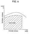
- the EGR zone covers the lean stratified charge zone (I), the lean homogeneous charge zone (II) and the enriched homogeneous charge zone (III) excepting a higher engine loading region for warm conditions, and the enriched homogeneous charge zone (A) excepting a higher engine loading region for cold conditions.
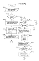
- Figures 5(A) through 5(D) show a flow chart illustrating a sequence routine of fuel charge control.
- step S101 signals Ne, Tv, Qa, Tw and Ss representative of various control factors such as engine speed, accelerator position, intake air quantity, cooling water temperature and a starter signal respectively are read into the control unit 41.
- step S102 a decision is made at step S102 as to whether the engine 1 starts.
- an engine start is ascertained.
- an injection pulse width TaK at the engine start is calculated at step S103.
- the given amount of fuel is divided into two parts for early fuel injection and later fuel injection made in an intake stroke according to a split ratio represented by a split factor c (1 > 0).
- the injection pulse width TaK is divided into two split injection pulse widths TaKl which is expressed by c x TaK and TaK2 which is expressed by (1 - c) x TaK at step S104.
- a given amount of fuel is neither sprayed in non-split suction stroke injection nor in non-split compression stroke injection, and simultaneously both non-split suction stroke injection pulse width TaK3 and non-spilt compression stroke injection pulse width TaD are set to 0 (zero).
- split injection timings s1 and s2 for the early and later fuel injection are determined, respectively, at step S105.
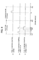
- the early and late split injection timings s1 and s2 are predetermined. That is, the early split injection timing s1 for the early fuel injection is dictated by an angle of rotation of the crankshaft 7 in an early half of a suction stroke and, more specifically, at a crank angle 45 to 50 degrees before top-dead-centre in a suction stroke, and the late split injection is timed to start at a point or timing s2 in a later half of the suction stroke and, more specifically, at a crank angle 100 to 120 degrees after top-dead-centre in the suction stroke.
- step S117 After the determination of early and late split injection timings s1 and s2 at step S105, a decision is made at step S117 as to whether it is the early split injection timing s1 for the early fuel injection. After waiting up to the early split injection timing s1 at step S117, the fuel injector 14 is pulsed to open to deliver the amount of fuel depending upon the early split injection pulse width TaK1 at step S118. Similarly, a decision is subsequently made at step S119 as to whether it is the late split injection timing s2 for the later fuel injection. After waiting up to the late split injection timing s2 at step S119, the fuel injector 14 is pulsed to open to deliver the amount of fuel depending upon the late split injection pulse width TaK2 at step S120. After a conclusion of the late split injection at step S120, the flow chart logic returns to restart the sequence routine.
- step S106 another decision is made at step S106 as to whether the cooling water temperature Tw is higher than a specified value Two, i.e. whether the engine 1 is in a warm condition.
- step S107 still another decision is made at step S107 as to whether the engine operating condition is in the lean stratified charge zone (I) for lower engine loadings and middle to higher engine speeds of the fuel charge control map for warm engine operation shown in Figure 2.
- a non-split compression stroke injection pulse width TaD for the lean stratified charge combustion is calculated at step S108.
- both split injection pulse widths Takl and Tak2 and non-split suction stroke injection pulse width TaK3 are set to 0 (zero) at step S109.
- a non-split compression stroke injection timing s3 is determined at step S110. As shown by (a) in Figure 6, the non-split compression stroke injection timing s3 is predetermined. That is, the non-split compression stroke injection timing s3 is set in a later half of a compression stroke. Subsequently, a decision is made at step S111 as to whether it is the injection timing s3 for the non-split compression stroke injection.
- the fuel injector 14 After waiting up to the non-split compression stroke injection timing s3 at step S111, the fuel injector 14 is pulsed to open to deliver the amount of fuel depending upon the non-split compression stroke injection width TaD at step S112. After a conclusion of the non-split compression stroke injection, the flow chart logic returns to restart the sequence routine.
- step S113 When the answer to the decision as to engine operating condition made at step S107 is negative, another decision is subsequently made at step S113 as to whether the engine operating condition is in the lean homogeneous charge zone (II) for lower engine loadings and lower to middle engine speeds of the fuel charge control map for warm engine operation shown in Figure 2.
- an injection pulse width TaK for lean homogeneous charge combustion is calculated at step S114.
- the given amount of fuel is divided into two parts for early fuel injection and later fuel injection made in a suction stroke according to a split ratio represented by a split factor a (1 > 0) at step S115.
- the injection pulse width TaK is divided into an early split injection pulse width TaK1 which is expressed by a x TaK and a late split injection pulse width TaK2 which is expressed by (1 - a) x TaK.
- the given amount of fuel is neither sprayed in non-split suction stroke injection nor in non-split compression stroke injection and consequently both non-split suction stroke injection pulse width TaK3 and non-spilt compression stroke injection pulse width TaD are set to 0 (zero).
- early and late split injection timings s1 and s2 are determined as shown by (b) in Figure 6 at step S116.
- the fuel injector 14 After waiting up to the early split injection timing s1 at step S117, the fuel injector 14 is pulsed to open to deliver the amount of fuel depending upon the early split injection pulse width TaK1 at step S118.
- the fuel injector 14 After waiting up to the late split injection timing s2 at step S119, the fuel injector 14 is pulsed to open to deliver the amount of fuel depending upon the late split injection pulse width TaK2 at step S120.
- the flow chart logic After a conclusion of the late split injection at step S120, the flow chart logic returns to restart the sequence routine.
- step S121 When the engine operating condition is out of the lean homogeneous charge zone (II), another decision is subsequently made at step S121 as to whether the engine operating condition is in the enriched homogeneous charge zone (III) for middle to higher engine loadings and lower to higher engine speeds of the fuel charge control map for warm engine operation shown in Figure 2.
- an injection pulse width TaK for enriched homogeneous charge combustion is calculated at step S122.
- the given amount of fuel is divided into two early fuel injection and later fuel injection made in a suction stroke according to a split ratio represented by a split factor b (1 > 0) at step S123.
- the injection pulse width TaK is divided into an early split injection pulse width TaK1 which is expressed by b x TaK and a late split injection pulse width TaK2 which is expressed by (1 - b) x TaK.
- the given amount of fuel is sprayed neither in non-split suction stroke injection nor in non-split compression stroke injection and consequently both non-split suction stroke injection pulse width TaK3 and non-spilt compression stroke injection pulse width TaD are set to 0 (zero).
- early and late split injection timings s1 and s2 are determined as shown by (b) in Figure 6 at step S124.
- the fuel injector 14 After waiting up to the early split injection timing s1 at step S117, the fuel injector 14 is pulsed to open to deliver the amount of fuel depending upon the early split injection pulse width TaKl at step S118. Similarly, after waiting up to the late split injection timing s2 at step S119, the fuel injector 14 is pulsed to open to deliver the amount of fuel depending upon the late split injection pulse width TaK2 at step S120. After a conclusion of the late split injection at step S120, the flow chart logic returns to restart the sequence routine.
- an injection pulse width TaK for enriched homogeneous charge combustion is calculated at step S126.
- the injection pulse width TaK is employed as a non-split suction stroke injection pulse width TaK3 at step S127.
- both split injection pulse widths Takl and Tak2 and non-split compression stroke injection pulse width TaD are set to 0 (zero).
- a non-split suction stroke injection timing s4 is determined at step S128.
- the non-split suction stroke injection timing s4 is predetermined. That is, the non-split suction stroke injection timing s4 is set such that the non-split suction stroke injection is started at approximately the midpoint of a suction stroke.
- the fuel injector 14 is pulsed to open to deliver the amount of fuel depending upon the non-split suction stroke injection width TaK3 at step S130.
- the flow chart logic After a conclusion of the non-split suction stroke injection, the flow chart logic returns to restart the sequence routine.
- step S106 when the answer to the decision as to cooling water temperature Tw made at step S106 is negative, this indicates that the engine 1 is still in a cold condition, then, another decision is subsequently made at step S125 as to whether the engine operating condition is in the enriched homogeneous charge zone (A) for middle to middle to higher engine loadings of the fuel charge control map for cold engine operation shown in Figure 3.
- steps S122-S124 and S117 through S120 are taken to cause early and late split injection in a suction stroke to deliver the given amounts of fuel depending upon the early and late split injection pulse widths TaK1 and TaK2.
- the fuel injector 14 After waiting up to the non-split suction stroke injection timing s4 at step S129, the fuel injector 14 is pulsed to open to deliver the amount of fuel depending upon the non-split suction stroke injection width TaK3 at step S130. After a conclusion of the non-split suction stroke injection, the flow chart logic returns to restart the sequence routine.
- the midpoint m between the early and late split injection timings s1 and s2 is put before the midpoint M of a suction stroke which is at a crank angle of 90? after top-dead-centre.
- Each injection pulse split factor a, b, c is set approximately 0.5, which divides a given amount of fuel into two exact halves for early and later fuel injection.
- a given amount of fuel is divided into two parts and sprayed through early and late split injection in a suction stroke as shown (b) in Figure 6.
- Tw cooling water temperature
- a given amount of fuel is sprayed all at once in a suction stroke as shown by (c) in Figure 6.
- a given amount of fuel is sprayed all at once in a compression stroke as shown by (a) in Figure 6 when the engine 1 operates in the lean stratified charge zone (I) for lower engine loadings and lower to middle engine speeds or in a suction stroke as shown by (c) in Figure 6 when the engine 1 operates in the enriched homogeneous charge zone (IV) for higher engine loadings and higher engine speeds or in the enriched homogeneous charge zone (V) for lower engine loadings and middle to higher engine speeds.
- the engine operates in the zone in which a given amount of fuel is sprayed through early and late split injection in a suction stroke, i.e.
- the EGR valve 39 is actuated to admit exhaust gas in the exhaust line 31 partly into an intake air stream in the intake line 25.
- the exhaust gas recirculation (EGR) rate is significantly low while the engine operates with higher loadings in the enriched homogeneous charge zone (A) and the enriched homogeneous charge zone (III).
- the EGR valve 39 may be shut in the higher loading zone as shown in Figure 4.
- the part of fuel sprayed through the early split injection is sufficiently homogeneously diffused in the combustion chamber 6 with an increase in volume of the combustion chamber 6 following a down stroke of the piston 5 with absence of fuel injection before the late split injection.
- the part of fuel splayed through the late split injection is diffused, so as to provide a homogeneous distribution of air-fuel mixture in the combustion chamber 6. In this manner, the fuel distribution is homogenised in the combustion chamber without enhancing penetrating force of a spray of fuel.
- the early split injection can be made correspondingly at a point of time at which the piston 5 attains a relatively high down speed and in consequence causes an intake air stream to flow with a high velocity, accelerating accomplishment of both homogeneous distribution and evaporation of fuel.
- the early and late split injection which are shifted as one whole a little to the early side of a suction stroke prevents or significantly reduces sticking of sprayed fuel through the late split injection to the side wall of the cylinder bore 2 when the piston 5 reaches near bottom-dead-centre or at the end of a suction stroke, which is always desirable for a homogeneous distribution of fuel in the combustion chamber 6.
- a spray of fuel has penetration force which is not so high as was previously described, problems resulting from fuel stuck to the cylinder wall do not occur.
- the acceleration of accomplishment of a homogeneous distribution and evaporation of fuel is significantly enhanced by a rise in the temperature of intake air due to exhaust gas recirculation. Furthermore, while an air stream is admitted into the combustion chamber 6 through only one intake port 12 other than the intake port 12 with the air stream control valve 30 installed therein, a swirl of intake air is created in the combustion chamber 6, accelerating a homogeneous distribution of fuel with an effect of improving evaporation of the fuel. These effects mutually affect one another to increase the combustion velocity of fuel and decrease a combustion time, so as to significantly improve the combustion stability.
- the Pi coefficient variation and the specific fuel consumption are reduced as the late split injection timing s2 is advanced. Accordingly, in a zone where the given amount of fuel, and hence a injection pulse width, is small such as a zone for low engine loadings and low engine speeds, the combustion stability and specific fuel consumption are even more improved when the late split injection is advanced so as to be brought to an end before an crank angle of 120? after top-dead centre.
- the combustion stability is greatly improved by the split injection, expanding largely the lean limit.
- the air-fuel ratio is made more higher as compared to the prior art engine control system and the specific fuel consumption and the emission level of NOx are further lowered.
- the non-split injection when altering the air-fuel ratio higher while the engine 1 operates in the homogeneous charge combustion zone, the Pi coefficient variation sharply rises due to aggravation of combustion when the air-fuel ratio (A/F) is higher than approximately 23 to 25. It is apparent that the sharp rise in Pi coefficient variation is accompanied by aggravation of the specific fuel consumption.
- a target air-fuel ratio (A/F) has no choice but to be set to approximately 21. In other words, the non-split injection provides only unsatisfactory improvement of specific fuel consumption and an insufficient reduction in formation of NOx.
- the split injection made in a suction stroke permits the lean limit of air-fuel ratio (A/F) to be expanded to approximately 25 to 27. Accordingly, even when taking account of variations in practical fuel injection, it is possible to set a target air-fuel ratio (A/F) to approximately 23, which provides satisfactory improvement of specific fuel consumption and an sufficient reduction in formation of NOx in the lean homogeneous charge zone (II).
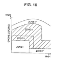
- Figure 10 shows a fuel charge control map for cold engine operation which is similar to that shown in Figure 2 but has an enriched homogeneous charge zone (IV) is expanded above an enriched homogeneous charge zone (III).
- the exhaust gas recirculation control is executed while the engine operates in the EGR zone shown in Figure 4 which covers the lean stratified charge zone (I), the lean homogeneous charge zone (II) and the enriched homogeneous charge zone (III).
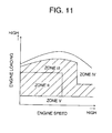
- FIG 11 shows a fuel charge control map for cold engine operation which is suitably used for fuel charge control of a direct injection-spark ignition engine of a type which does not have a stratified charge combustion feature.
- the fuel charge control map is similar to that shown in Figure 10 but, while having no lean stratified charge zone (I), defines an enriched homogeneous charge zone (V) lying over possible engine speeds in which non-split injection is made.
- This type of direct injection-spark ignition engine has no necessity of having a piston formed with a top cavity and provides a reduction in heat loss consequently.
Landscapes
- Engineering & Computer Science (AREA)
- Chemical & Material Sciences (AREA)
- Combustion & Propulsion (AREA)
- Mechanical Engineering (AREA)
- General Engineering & Computer Science (AREA)
- Electrical Control Of Air Or Fuel Supplied To Internal-Combustion Engine (AREA)
- Combined Controls Of Internal Combustion Engines (AREA)
- Combustion Methods Of Internal-Combustion Engines (AREA)
Applications Claiming Priority (6)
| Application Number | Priority Date | Filing Date | Title |
|---|---|---|---|
| JP324730/97 | 1997-11-26 | ||
| JP32473097 | 1997-11-26 | ||
| JP32473097 | 1997-11-26 | ||
| JP274625/98 | 1998-09-29 | ||
| JP27462598A JP3506018B2 (ja) | 1997-11-26 | 1998-09-29 | エンジンの制御装置 |
| JP27462598 | 1998-09-29 |
Publications (3)
| Publication Number | Publication Date |
|---|---|
| EP0919712A2 true EP0919712A2 (de) | 1999-06-02 |
| EP0919712A3 EP0919712A3 (de) | 2000-12-20 |
| EP0919712B1 EP0919712B1 (de) | 2004-06-09 |
Family
ID=26551116
Family Applications (1)
| Application Number | Title | Priority Date | Filing Date |
|---|---|---|---|
| EP98309718A Expired - Lifetime EP0919712B1 (de) | 1997-11-26 | 1998-11-26 | Steuersystem für eine funkgezündete Brennkraftmaschine mit Direkt-Einspritzung |
Country Status (4)
| Country | Link |
|---|---|
| EP (1) | EP0919712B1 (de) |
| JP (1) | JP3506018B2 (de) |
| KR (1) | KR19990045570A (de) |
| DE (1) | DE69824371T2 (de) |
Cited By (5)
| Publication number | Priority date | Publication date | Assignee | Title |
|---|---|---|---|---|
| US6055956A (en) * | 1998-09-29 | 2000-05-02 | Mazda Motor Corporation | Control system for an engine equipped with exhaust gas recirculation system |
| US6257197B1 (en) * | 1998-09-29 | 2001-07-10 | Mazda Motor Corporation | Control system for a direct injection-spark ignition engine |
| EP1300573A2 (de) * | 2001-10-02 | 2003-04-09 | Robert Bosch Gmbh | Verfahren zum Betreiben einer direkteinspritzenden Brennkraftmaschine, Steuergerät und Brennkraftmaschine |
| CN103291480A (zh) * | 2013-06-13 | 2013-09-11 | 清华大学 | 缸内直喷增压发动机超级爆震的抑制方法 |
| US9284909B2 (en) | 2013-08-23 | 2016-03-15 | Ford Global Technologies, Llc | Method and system for knock control |
Families Citing this family (2)
| Publication number | Priority date | Publication date | Assignee | Title |
|---|---|---|---|---|
| JP4341550B2 (ja) | 2004-12-27 | 2009-10-07 | トヨタ自動車株式会社 | 直噴式内燃機関の燃料噴射制御装置 |
| EP2470758B1 (de) | 2009-08-28 | 2015-05-06 | Umicore AG & Co. KG | Abgasnachbehandlungssystem mit katalytisch aktivem wandstromfilter mit speicherfunktion vor einem katalysator mit identischer speicherfunktion |
Citations (5)
| Publication number | Priority date | Publication date | Assignee | Title |
|---|---|---|---|---|
| EP0661432A2 (de) * | 1993-12-28 | 1995-07-05 | Hitachi, Ltd. | Verfahren und Vorrichtung zur Steuerung einer Brennkraftmaschine |
| US5479775A (en) * | 1993-04-23 | 1996-01-02 | Mercedes-Benz Ag | Air-compressing fuel-injection internal-combustion engine with an exhaust treatment device for reduction of nitrogen oxides |
| WO1996022457A1 (fr) * | 1995-01-20 | 1996-07-25 | Toyota Jidosha Kabushiki Kaisha | Procede de nettoyage des gaz d'echappement pour moteur a combustion interne |
| DE19636507A1 (de) * | 1995-09-22 | 1997-03-27 | Bosch Gmbh Robert | Verfahren und Vorrichtung zur Steuerung einer Brennkraftmaschine |
| EP0849459A1 (de) * | 1996-12-19 | 1998-06-24 | Mitsubishi Jidosha Kogyo Kabushiki Kaisha | Fremdgezündete direkt-eingespritzte Brennkraftmaschine |
Family Cites Families (1)
| Publication number | Priority date | Publication date | Assignee | Title |
|---|---|---|---|---|
| US5775099A (en) * | 1994-04-12 | 1998-07-07 | Toyota Jidosha Kabushiki Kaisha | Method of purifying the exhaust of an internal combustion engine |
-
1998
- 1998-09-29 JP JP27462598A patent/JP3506018B2/ja not_active Expired - Fee Related
- 1998-11-25 KR KR1019980050733A patent/KR19990045570A/ko active IP Right Grant
- 1998-11-26 EP EP98309718A patent/EP0919712B1/de not_active Expired - Lifetime
- 1998-11-26 DE DE69824371T patent/DE69824371T2/de not_active Expired - Lifetime
Patent Citations (5)
| Publication number | Priority date | Publication date | Assignee | Title |
|---|---|---|---|---|
| US5479775A (en) * | 1993-04-23 | 1996-01-02 | Mercedes-Benz Ag | Air-compressing fuel-injection internal-combustion engine with an exhaust treatment device for reduction of nitrogen oxides |
| EP0661432A2 (de) * | 1993-12-28 | 1995-07-05 | Hitachi, Ltd. | Verfahren und Vorrichtung zur Steuerung einer Brennkraftmaschine |
| WO1996022457A1 (fr) * | 1995-01-20 | 1996-07-25 | Toyota Jidosha Kabushiki Kaisha | Procede de nettoyage des gaz d'echappement pour moteur a combustion interne |
| DE19636507A1 (de) * | 1995-09-22 | 1997-03-27 | Bosch Gmbh Robert | Verfahren und Vorrichtung zur Steuerung einer Brennkraftmaschine |
| EP0849459A1 (de) * | 1996-12-19 | 1998-06-24 | Mitsubishi Jidosha Kogyo Kabushiki Kaisha | Fremdgezündete direkt-eingespritzte Brennkraftmaschine |
Cited By (8)
| Publication number | Priority date | Publication date | Assignee | Title |
|---|---|---|---|---|
| US6055956A (en) * | 1998-09-29 | 2000-05-02 | Mazda Motor Corporation | Control system for an engine equipped with exhaust gas recirculation system |
| US6257197B1 (en) * | 1998-09-29 | 2001-07-10 | Mazda Motor Corporation | Control system for a direct injection-spark ignition engine |
| EP1300573A2 (de) * | 2001-10-02 | 2003-04-09 | Robert Bosch Gmbh | Verfahren zum Betreiben einer direkteinspritzenden Brennkraftmaschine, Steuergerät und Brennkraftmaschine |
| EP1300573A3 (de) * | 2001-10-02 | 2006-04-19 | Robert Bosch Gmbh | Verfahren zum Betreiben einer direkteinspritzenden Brennkraftmaschine, Steuergerät und Brennkraftmaschine |
| CN103291480A (zh) * | 2013-06-13 | 2013-09-11 | 清华大学 | 缸内直喷增压发动机超级爆震的抑制方法 |
| US9284909B2 (en) | 2013-08-23 | 2016-03-15 | Ford Global Technologies, Llc | Method and system for knock control |
| US9664128B2 (en) | 2013-08-23 | 2017-05-30 | Ford Global Technologies, Llc | Method and system for knock control |
| US9840976B2 (en) | 2013-08-23 | 2017-12-12 | Ford Global Technologies, Llc | Method and system for knock control |
Also Published As
| Publication number | Publication date |
|---|---|
| EP0919712B1 (de) | 2004-06-09 |
| DE69824371T2 (de) | 2004-10-07 |
| EP0919712A3 (de) | 2000-12-20 |
| DE69824371D1 (de) | 2004-07-15 |
| JP3506018B2 (ja) | 2004-03-15 |
| KR19990045570A (ko) | 1999-06-25 |
| JPH11218049A (ja) | 1999-08-10 |
Similar Documents
| Publication | Publication Date | Title |
|---|---|---|
| EP1291512B1 (de) | Verfahren und Vorrichtung für direkteinspritzende Otto-Brennkraftmaschine, direkteinspritzende Otto-Brennkraftmaschine, Computer lesbares Speichermedium, Computerprogram | |
| US5967113A (en) | Exhaust-gas temperature raising system for an in-cylinder injection type internal combustion engine | |
| US6116208A (en) | Control system for a direct injection-spark ignition engine | |
| US6067954A (en) | Direct fuel injection engine | |
| EP0978643B1 (de) | Steuervorrichtung für eine Brennkraftmaschine mit Direkteinspritzung | |
| EP1243779B1 (de) | Brennkraftmaschine mit Direkteinspritzung mit einem Turbolader und Verfahren zu ihrer Steuerung | |
| US6085718A (en) | Control system for a direct injection-spark ignition engine | |
| US5765372A (en) | Lean burn engine for automobile | |
| US6257197B1 (en) | Control system for a direct injection-spark ignition engine | |
| EP1028243B1 (de) | Steuervorrichtung für eine Brennkraftmaschine mit Direkteinspritzung | |
| US7168409B2 (en) | Controller for direct injection internal combustion engine | |
| EP1088980A2 (de) | Verfahren und Vorrichtung zur Steuerung einer Brennkraftmaschine | |
| JP2001342836A (ja) | 火花点火式直噴エンジン | |
| EP0919711B1 (de) | Steuersystem für eine funkgezündete Brennkraftmaschine mit Direkt-Eispritzung | |
| EP0919714B1 (de) | Steuersystem für eine funkgezündete Brennkraftmaschine mit Direkt-Einspritzung | |
| US6513320B1 (en) | Control system for a direct injection-spark ignition engine | |
| EP0919712B1 (de) | Steuersystem für eine funkgezündete Brennkraftmaschine mit Direkt-Einspritzung | |
| EP0919713B1 (de) | Steuersystem für eine funkgezündete Brennkraftmaschine mit Direkt-Einspritzung | |
| EP0919709B1 (de) | Steuersystem für eine Brennkraftmaschine mit Abgasrückführungssystem | |
| US6055956A (en) | Control system for an engine equipped with exhaust gas recirculation system | |
| JP2003227338A (ja) | 火花点火式直噴エンジン | |
| EP1517017A1 (de) | Fremdgezündete Brennkraftmaschine mit Direkt-Einspritzung | |
| JP2003106186A (ja) | 火花点火式直噴エンジンの制御装置 | |
| JP2003106195A (ja) | 火花点火式直噴エンジンの制御装置 | |
| JP3269350B2 (ja) | 筒内噴射型火花点火式内燃機関 |
Legal Events
| Date | Code | Title | Description |
|---|---|---|---|
| PUAI | Public reference made under article 153(3) epc to a published international application that has entered the european phase |
Free format text: ORIGINAL CODE: 0009012 |
|
| AK | Designated contracting states |
Kind code of ref document: A2 Designated state(s): DE ES FR GB IT |
|
| AX | Request for extension of the european patent |
Free format text: AL;LT;LV;MK;RO;SI |
|
| PUAL | Search report despatched |
Free format text: ORIGINAL CODE: 0009013 |
|
| AK | Designated contracting states |
Kind code of ref document: A3 Designated state(s): AT BE CH CY DE DK ES FI FR GB GR IE IT LI LU MC NL PT SE |
|
| AX | Request for extension of the european patent |
Free format text: AL;LT;LV;MK;RO;SI |
|
| RIC1 | Information provided on ipc code assigned before grant |
Free format text: 7F 02D 41/40 A, 7F 02D 41/14 B |
|
| 17P | Request for examination filed |
Effective date: 20010529 |
|
| AKX | Designation fees paid |
Free format text: DE ES FR GB IT |
|
| 17Q | First examination report despatched |
Effective date: 20030318 |
|
| GRAP | Despatch of communication of intention to grant a patent |
Free format text: ORIGINAL CODE: EPIDOSNIGR1 |
|
| GRAS | Grant fee paid |
Free format text: ORIGINAL CODE: EPIDOSNIGR3 |
|
| GRAA | (expected) grant |
Free format text: ORIGINAL CODE: 0009210 |
|
| AK | Designated contracting states |
Kind code of ref document: B1 Designated state(s): DE ES FR GB IT |
|
| PG25 | Lapsed in a contracting state [announced via postgrant information from national office to epo] |
Ref country code: IT Free format text: LAPSE BECAUSE OF FAILURE TO SUBMIT A TRANSLATION OF THE DESCRIPTION OR TO PAY THE FEE WITHIN THE PRESCRIBED TIME-LIMIT;WARNING: LAPSES OF ITALIAN PATENTS WITH EFFECTIVE DATE BEFORE 2007 MAY HAVE OCCURRED AT ANY TIME BEFORE 2007. THE CORRECT EFFECTIVE DATE MAY BE DIFFERENT FROM THE ONE RECORDED. Effective date: 20040609 Ref country code: FR Free format text: LAPSE BECAUSE OF FAILURE TO SUBMIT A TRANSLATION OF THE DESCRIPTION OR TO PAY THE FEE WITHIN THE PRESCRIBED TIME-LIMIT Effective date: 20040609 |
|
| REG | Reference to a national code |
Ref country code: GB Ref legal event code: FG4D |
|
| REF | Corresponds to: |
Ref document number: 69824371 Country of ref document: DE Date of ref document: 20040715 Kind code of ref document: P |
|
| PG25 | Lapsed in a contracting state [announced via postgrant information from national office to epo] |
Ref country code: ES Free format text: LAPSE BECAUSE OF FAILURE TO SUBMIT A TRANSLATION OF THE DESCRIPTION OR TO PAY THE FEE WITHIN THE PRESCRIBED TIME-LIMIT Effective date: 20040920 |
|
| PG25 | Lapsed in a contracting state [announced via postgrant information from national office to epo] |
Ref country code: GB Free format text: LAPSE BECAUSE OF NON-PAYMENT OF DUE FEES Effective date: 20041126 |
|
| PLBE | No opposition filed within time limit |
Free format text: ORIGINAL CODE: 0009261 |
|
| STAA | Information on the status of an ep patent application or granted ep patent |
Free format text: STATUS: NO OPPOSITION FILED WITHIN TIME LIMIT |
|
| 26N | No opposition filed |
Effective date: 20050310 |
|
| EN | Fr: translation not filed | ||
| GBPC | Gb: european patent ceased through non-payment of renewal fee |
Effective date: 20041126 |
|
| PGFP | Annual fee paid to national office [announced via postgrant information from national office to epo] |
Ref country code: DE Payment date: 20101124 Year of fee payment: 13 |
|
| REG | Reference to a national code |
Ref country code: DE Ref legal event code: R119 Ref document number: 69824371 Country of ref document: DE Effective date: 20120601 |
|
| PG25 | Lapsed in a contracting state [announced via postgrant information from national office to epo] |
Ref country code: DE Free format text: LAPSE BECAUSE OF NON-PAYMENT OF DUE FEES Effective date: 20120601 |