EP0918903B1 - Doppelsiebformer für eine papiermaschine - Google Patents
Doppelsiebformer für eine papiermaschine Download PDFInfo
- Publication number
- EP0918903B1 EP0918903B1 EP97929326A EP97929326A EP0918903B1 EP 0918903 B1 EP0918903 B1 EP 0918903B1 EP 97929326 A EP97929326 A EP 97929326A EP 97929326 A EP97929326 A EP 97929326A EP 0918903 B1 EP0918903 B1 EP 0918903B1
- Authority
- EP
- European Patent Office
- Prior art keywords
- wire
- forming
- twin
- water
- former
- Prior art date
- Legal status (The legal status is an assumption and is not a legal conclusion. Google has not performed a legal analysis and makes no representation as to the accuracy of the status listed.)
- Expired - Lifetime
Links
- XLYOFNOQVPJJNP-UHFFFAOYSA-N water Substances O XLYOFNOQVPJJNP-UHFFFAOYSA-N 0.000 claims abstract description 108
- 239000000725 suspension Substances 0.000 claims abstract description 17
- 230000033228 biological regulation Effects 0.000 claims description 23
- 238000007789 sealing Methods 0.000 claims description 20
- 238000009826 distribution Methods 0.000 claims description 7
- 230000001105 regulatory effect Effects 0.000 claims description 7
- 239000000919 ceramic Substances 0.000 claims description 6
- 238000005259 measurement Methods 0.000 claims description 4
- 230000001276 controlling effect Effects 0.000 claims description 3
- 238000005192 partition Methods 0.000 claims description 3
- 238000004891 communication Methods 0.000 claims description 2
- 230000015572 biosynthetic process Effects 0.000 description 11
- 238000010276 construction Methods 0.000 description 10
- 210000000481 breast Anatomy 0.000 description 6
- 230000001965 increasing effect Effects 0.000 description 5
- 230000000694 effects Effects 0.000 description 4
- 239000000835 fiber Substances 0.000 description 4
- 239000007787 solid Substances 0.000 description 4
- 230000037303 wrinkles Effects 0.000 description 3
- 230000014759 maintenance of location Effects 0.000 description 2
- 239000000463 material Substances 0.000 description 2
- 230000001133 acceleration Effects 0.000 description 1
- 230000002542 deteriorative effect Effects 0.000 description 1
- 230000001627 detrimental effect Effects 0.000 description 1
- 230000002708 enhancing effect Effects 0.000 description 1
- 239000004744 fabric Substances 0.000 description 1
- 239000000945 filler Substances 0.000 description 1
- 238000005189 flocculation Methods 0.000 description 1
- 239000011888 foil Substances 0.000 description 1
- 244000144972 livestock Species 0.000 description 1
- 230000035515 penetration Effects 0.000 description 1
- 230000010349 pulsation Effects 0.000 description 1
- 230000000717 retained effect Effects 0.000 description 1
- 230000000630 rising effect Effects 0.000 description 1
- 238000000926 separation method Methods 0.000 description 1
- 230000003068 static effect Effects 0.000 description 1
- 239000013589 supplement Substances 0.000 description 1
- 238000005406 washing Methods 0.000 description 1
Images


Classifications
-
- D—TEXTILES; PAPER
- D21—PAPER-MAKING; PRODUCTION OF CELLULOSE
- D21F—PAPER-MAKING MACHINES; METHODS OF PRODUCING PAPER THEREON
- D21F9/00—Complete machines for making continuous webs of paper
- D21F9/003—Complete machines for making continuous webs of paper of the twin-wire type
Definitions
- the present invention relates to a twin-wire gap former in a paper machine comprising an outer wire and an inner wire which are guided by guide rolls and web forming members to form a twin-wire zone therebetween.
- the twin-wire zone starts from a forming gap defined by a convergence of the wires toward one another into which a slice part of a headbox feeds a stock suspension jet.
- the forming gap is substantially directly followed by a curved portion of the twin-wire zone which is provided with its curved form by a first forming roll placed inside a loop of one of the wires.
- a stock suspension jet is fed into a wedge-shaped narrowing gap between the forming wires.
- the stock suspension jet is directed at an unsupported "outer" wire at a certain impingement angle.
- the live stock suspension jet produces instability and in particular cross-direction wrinkles, wave formation and vanes in the unsupported wire, in particular in the lateral areas of the wire.
- the tendency of wrinkles and the formation of waves in the wire produce a variation in the grammage of the finished paper or board produced from the web both in the machine direction and in the cross-machine direction.
- gap formers typically either two opposed forming rolls are used, which operate as breast rolls and are placed inside the loops of each of the wires, or alternatively in the gap area, one forming roll is used, which is placed inside the loop of one of the wires, whereas the other wire is passed into contact with the forming roll by means of guide rolls.
- the geometry of the forming gap usually becomes such that it is difficult to place the slice opening of the slice part of the headbox sufficiently deep in the forming gap, for example, because the devices for regulation of the profile bar of the slice opening require a considerably large space and hinder penetration of the slice part into the forming gap.
- the flight distance of the stock suspension jet departing from the headbox is a critical factor in many respects.
- a relatively long flight distance of the jet subjects the jet to air currents in the forming gap, in which case the point of impingement of the jet may be changed and/or the surface of the jet may disintegrate while deteriorating the formation and possibly also other properties of the paper.
- a long flight distance of the jet when no turbulence arising from differences in speed produced by walls is present, increases re-flocculation of the fibers detrimentally.
- This forming gap arrangement comprises two opposite support members whose inner sides are arranged as direct extensions of the inner sides of the lip walls that define the slice channel.
- the support members are arranged to extend into the forming gap substantially parallel to one another so that the free ends of the support members are placed in the direct vicinity of (proximate to), or in contact with, the forming wires.
- the support members are made of a plate-like material which is, at least to some extent, resilient.
- one of the starting points of the present invention is the prior art support member or foil extension arrangements known from FI Patent Application No. 905896 and from the corresponding published EP Patent Application No. 0 488 058, by whose means, however, all problems cannot be solved and the objectives of the present invention cannot be achieved.
- the present invention expressly concerns roll gap formers, with respect to which, as one example, reference is made to the current assignee's Finnish Patent No. 83,102.
- advantageous features of roll gap formers are described, which features are also retained in the present invention.
- This prior art former and other, corresponding formers have required further development in particular in connection with the curved twin-wire zone placed on the first forming roll directly after the forming gap, in particular with respect to the controllability of the drainage/dewatering of water thereat.
- drainage of water takes place through both wires, and to a certain extent also towards the forming roll placed at the side of the inside curve if a forming roll that has an open face and that is in particular provided with suction is used as the forming roll.
- a former by means of the ratio of the velocity of the slice jet to the speed of the wire, it is possible to affect the formation of the paper and in particular its fiber orientation.
- the former in accordance with the invention includes an arrangement of a forming gap which comprises two opposite lip plates which define a slice channel between them.
- the lip plates are arranged to extend substantially parallel to one another and penetrate deep into the forming gap so that the free ends of the lip plates are placed in the direct vicinity of the forming wires or in contact with the wires.
- the construction operates as well with plates.
- a water drainage box is situated on the curve sector of the twin-wire zone, which starts substantially directly after the forming gap and which is guided in its curve by the first forming roll positioned inside the loop of one of the wires.
- the sides that are placed against the inner face of the wire are substantially sealed against the wire by appropriate sealing means, and the water drainage box is connected to devices which individually regulate the pressure/pressures in the space or spaces placed in the interior of the box and which are filled with water.
- the water drainage box is connected to devices which individually regulate the pressure/pressures in the space or spaces placed in the interior of the box and which are filled with water.
- the dewatering can be made fully controlled both in the area of the forming gap and on the curve sector of the twin-wire zone on the first forming roll following substantially directly after the forming gap.
- this curve sector the major part of the drainage of water from the web takes place.
- the drainage of water can be started sufficiently gently and the dewatering pressure be increased gradually so that the retention becomes good.
- the twin-wire gap former in a paper machine in accordance with the invention comprises first and second wires guided in respective loops by guide rolls and web forming members and having a joint run which constitutes a twin-wire forming zone, a forming gap being defined by the first and second wires at a beginning of the twin-wire zone.
- a stock suspension jet is fed from a slice part of a headbox into the forming gap between the first and second wires to form a web.
- a first forming roll is arranged inside the loop of the first wire and substantially directly after the forming gap in a web running direction.
- the twin-wire zone follows a curved run about a sector of the first forming roll.
- Two opposed elongate lip plates extend substantially parallel to one another to define a slice channel therebetween.
- the slice channel extends into the forming gap and is in flow communication with the slice part of the headbox.
- a free end of each lip plate proximate the forming gap is situated proximate or in contact with a respective one of the first and second wires.
- the former also includes water drainage means arranged inside the loop of the second wire in opposed relationship to at least a portion of the curved run of the twin-wire zone for draining water from the web.
- the water drainage means comprise means defining at least one water-filled chamber and sealing means in direct contact with an inner face of the second wire for sealing the at least one chamber. Regulation means are then coupled to each chamber for regulating the pressure of the water in that chamber to thereby control dewatering of the web in the curved run of the twin-wire zone.
- the means defining the chamber may comprise a front wall arranged proximate to the forming gap, one of the lip plates situated closer to the second wire extending in opposed relationship to the front wall or substantially to the vicinity of the front wall to prevent release of stock onto the second wire at a location before the at least one chamber.
- the water drainage means preferably comprise a water drainage box extending substantially over the entire area of the curved run of the twin-wire zone.
- the means defining the define a plurality of successively arranged chambers and the sealing means comprise cross-direction partition walls for separating the chambers from one another.
- the regulation means comprise a pump and a plurality of regulation valves coupled to the pump and to a respective one of the chambers such that the pressure in each of the chambers is individually controlled to thereby control the amount of water and distribution of the drainage of water taking place through the second wire.
- the means defining the chamber may also comprise at least two walls each having a respective edge proximate the inner face of the second wire and the sealing means may thus comprise wear ribs fixedly connected to the wall edges and contacting the inner face of the second wire.
- the sealing means comprise wear ribs movably connected to the wall edges and contacting the inner face of the second wire.
- adjusting means are coupled to each of the wear ribs for adjusting a position of the wear ribs relative to the second wire.
- the sealing means may comprise spring-loaded wear ribs coupled to the wall edges and biased toward the inner face of the second wire.
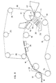
- Figure 1 is a schematic illustration of a roll gap twin-wire former as an environment of application of the present invention.
- Figure 2 shows a first exemplifying embodiment of the initial portion of the forming zone in a former in accordance with the invention.
- Figure 3 shows, in a manner corresponding to Fig. 2, a second exemplifying embodiment of the invention.
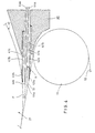
- Figure 4 shows an exemplifying embodiment of the forming gap applied in the present invention.
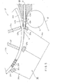
- Figure 5 shows an exemplifying embodiment of the forming gap in accordance with the invention and the subsequently arranged water drainage box arrangement in accordance with the invention.
- Figure 6 shows an exemplifying embodiment of the sealing ribs in the arrangement of water drainage boxes in accordance with the invention.
- Figure 7 shows, in a manner corresponding to Fig. 6, an alternative arrangement of loading/relief of sealing ribs.
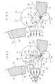
- Figure 8 shows a roll gap twin-wire former in accordance with the invention in a horizontal orientation.
- FIG. 1 is a schematic side view of a former, as an environment of application of the present invention, which former comprises an outer wire 10 guided in a loop, an inner wire 20 guided in a loop as well as a first web forming roll 21, a second web forming roll 25 and a breast roll 11.
- a former comprises an outer wire 10 guided in a loop, an inner wire 20 guided in a loop as well as a first web forming roll 21, a second web forming roll 25 and a breast roll 11.
- Each of the web forming rolls 21 and 25 is placed inside the loop of the inner wire 20, and the breast roll 11 is placed inside the loop of the outer wire 10.
- the outer wire 10 is a so-called covering wire
- the inner wire 20 is a so-called carrying wire, i.e., the web is carried thereon after the twin-wire zone, and the web W follows the inner wire 20 after the twin-wire forming zone which ends at a location around the second forming roll 25.
- a headbox 40 directs a pulp stock/suspension jet into a forming gap K between the breast roll 11 and the first web forming roll 21.
- the headbox 40 has slice parts 42a,42b through which the stock jet of the headbox 40 is directed into the gap K defined by the wires 10 and 20.
- the gap K is formed as determined by the relative positions of the rolls 11 and 21, which may be movable to different configurations as needed.
- the gap K is defined from one side by the inner wire 20, which is mainly guided by a guide roll 26a and covers the first forming roll 21, and from the other side by the outer wire 10, which is passed over the breast roll 11 onto the forming roll 21 at the beginning of its sector a to meet the inner wire 20.
- the stock suspension layer is thus placed between wires 10 and 20.
- the narrowing slice channel of the headbox 40 is followed by the plate-like lip plates 42a and 42b, which define a straight (non-narrowing or tapering) slice channel 41 having a substantially uniform width.
- the lip plates 42a and 42b are preferably made of a somewhat wear-resistant material, such as mesh-reinforced and/or fiber-reinforced, wear-resistant plastic. As comes out best from Figs. 4 and 5, the lip plates 42a and 42b join the preceding slice channel 41 smoothly without steps.
- the lip plates 42a and 42b extend to the bottom of the forming gap K so that wedge-shaped tip portions 43a and 43b of the lip plates 42a and 42b, respectively, are placed in the direct vicinity of (proximate to) the wires 10 and 20 or in contact with the wires 10,20. Since the slice channel 41 does not become narrower any longer in the area of the lip plates 42a,42b, the stock suspension flow F is not accelerated in the slice channel 41, at least not substantially. Thus, in the slice channel 41, the energy of the stock suspension flow is present as a static pressure. As such, it is also apparent that the speed of the stock suspension jet in the slice channel 41 is substantially constant.
- a water drainage box 30 is arranged inside the outer wire 10 in opposed relationship to the curve sector a of the twin-wire zone on the first forming roll 21, which is also referred as a curved run of the twin-wire zone.
- the water drainage box has been divided, directly from the bottom of the forming gap K and from the beginning of the curve sector a , into successively arranged drainage chambers 31a,31b,31c and 31d.
- the water drainage chambers 31 extend across the entire width of the web W up to the lateral areas of the wires 10,20.
- the water drainage chambers 31 are, at both sides, also provided with vertical end walls placed in the machine direction.
- the end wall have edges at the side of the forming roll 21 which are positioned against the inner face of the outer wire 10 and are, if necessary, provided with sealing ribs (not shown).
- the water drainage chambers 31 are completely filled with water.
- Each of the chambers 31 communicates with a respective water drainage duct 33, each of which is provided with a separate regulation means such as a valve 32 which regulates the water drainage pressures and water amounts in the chambers 31.
- a valve 32 By means of these valves 32, it is possible to control the pressures in the chambers 31a,...,31d and thus, to control the amounts and distributions of the drainage of water on individual portions of the curve sector a of the twin-wire zone through the outer wire 10.
- valves 32 From the side opposite in relation to the water drainage chamber 31, the valves 32 communicate through the water ducts 33 with a pump 34, which produces suitable pressures in the chambers 31a,...,31d filled with water.
- the valves 32 are either controlled manually, and/or the valves 32 can be connected to regulation/measurement devices, which are represented in Fig. 1 schematically by the block 35 and by the regulation connection 36 passing from the block 35 to all of the regulation valves 32.
- the block 35 also illustrates the possible embodiment in which the regulation of the valve 32 takes place by the principle of closed feed-back connected regulation based on measurement of the properties of the web W that is being formed. In this case, the regulation control system represented by block 35 would operate to control the settings of valves 32 accordingly to correct deviations if present.
- a former in which the twin-wire zone is vertically rising from the bottom toward the top
- the invention can also be applied to formers in which the twin-wire zone is substantially horizontal as shown in Fig. 8.
- a horizontal former has, for example, such a construction that, in Fig. 1, it is imagined that the vertical former therein is rotated 90° counter-clockwise, the forming roll 25 is substituted for by the guide roll of the upper wire 20, and the web W is arranged so that, after the twin-wire zone, it follows the lower wire 10, from which it is separated in a way in itself known by means of a pick-up roll.
- Other non-vertical, non-horizontal paths of the twin-wire zone e.g., inclined, are also within the scope of the invention.
- the first forming roll 21 is a suction roll having a revolving mantle 21V provided with perforations 21P (seen more clearly in Fig. 5).
- fixed suction chambers 21a, 21b, 21c and 21d are arranged with a spacing in the machine direction corresponding to, i.e., in alignment with, a respective one of the chambers 31a,...,31d in the water drainage box 30.
- Suction chambers 21a,...,21d are separated from one another by partition walls 27.
- the levels of the vacuum pressure acting in the different chambers 21a,...,21d can be regulated, and by means of this regulation, together with the regulation of the pressures in the water drainage chambers 31a,...,31d in the water drainage box 30, it is possible to affect and accurately control the amount and the distribution of the drainage of water on the curve sector a of the twin-wire zone on the forming roll 21.
- a hollow-faced roll for example a blind-drilled roll, without an inside suction chamber or even a solid-mantle forming roll 21 provided with a smooth outer face 21' shown in Fig. 3. Then on the sector a , no drainage of water takes place through the inner wire 20, but all the drainage of water on the sector a is carried out towards the water drainage box 30 through the outer wire 10.
- the level and distribution of the amount of drainage of water on the sector a is regulated solely by means of the control of the pressures in the chambers 31a,...,31d in the water drainage box, e.g., by means of the regulation of the valves 32 and possibly also of the pump 34.
- Figs. 2 and 3 show the number of the chambers 31a,...,31d in the water drainage box 30 as four, but within the scope of the invention it is also possible to use a different number of the chambers 31, in exceptional cases, for example, just one chamber, or even more than four chambers.
- This minimum pressure is generally of an order of from about 2 kPa to about 15 kPa. At the maximum, the pressure corresponds to the pressure in the slice channel 41 of the headbox, which is about 450 kPa.
- the pressure in the chambers 31 When the pressure in the chambers 31 is equal to the pressure in the slice channel 41 of the headbox, no substantial drainage of water takes place through the outer wire 10. In an exceptional case, it is also possible to use a vacuum in the chambers 31.
- the pressures in the chambers 31a,...,31d may be staggered so that an optimal distribution of the drainage of water on the sector a is obtained.
- the pressures in the chambers 31a,31b are lowered in the direction of progress of the web W so that drainage of water is started very gently in the area of the first chamber 31a on the sector a , and the intensity of drainage is increased stepwise in the areas of the different chambers 31b,31c,31d by the lowering of the pressures in the chambers 31.
- the lip plates 42a,42b extend to the bottom or extreme end of the forming gap K and to the front edge (defined by rib 37a) or to the vicinity of the front edge of the first water drainage chamber 31a in the water drainage box 30. For this reason, controlled drainage of water through the outer wire 10 does not start substantially until in the area of the water drainage box 30, whereby drainage of water is brought better under control by regulating the pressures in the chambers 31a,...,31d filled with water. In fact, any drainage of water through the outer wire 10 is substantially prevented by this construction.
- Fig. 4 shows a forming gap arrangement applied in the invention in which two plate-like intermediate plates 44a and 44b are arranged between the lip plates 42a,42b and spaced therefrom.
- the plates 42a,42b,44a,44b thus define three component ducts 41a,41b,41c placed one above the other between the plates 42a,42b, through which ducts the stock suspension flow F is discharged into the gap formed by the wires 10,20.
- the intermediate plates 44a,44b extend somewhat beyond the tips 43a and 43b of the lip plates in the flow direction F.
- Fig. 5 shows an embodiment of the invention in which the first forming roll 21 is a suction roll, whose first suction zone 21a starts at the tips 43a,43b of the lip plates 42a,42b, i.e., in opposed relationship to the tip 43b, and the first chamber 31a of the water drainage box 30 placed inside the outer wire 10 also starts at the same location.
- a ceramic sealing rib 37a is placed on the front wall of the chamber 31a and is pressed against the inner face of the outer wire 10, i.e., in opposed relationship to the tip 43a.
- Fig. 6 illustrates the sealing of a chamber 31 in the water drainage box 30 against the inner face of the outer wire 10 on the forming roll 21.
- ceramic wear ribs 37K are fixed permanently to the cross-direction walls of the chamber 31. This permanent fixing of the ribs 37K is denoted with the reference 39K.
- the ribs 37K and 37P of the chambers 31 have been arranged at an angle b "with the fur" in relation to the inner face of the outer wire 10 so that a risk of breaking of the wires 10,20 is avoided. This means that the first end of the ribs 37K,39K in the web running direction is spaced from the wire 10 whereas the second end of the ribs 37K,39K in the web running direction is placed against the wire 10.
- ceramic ribs 37P are attached to spring and/or loading elements 38a,38b by means of articulated joints 39P placed in the cross direction of the paper machine.
- the ribs 37P are mounted on the elements 38a,38b alone, in which case, by means of the elements 38a,38b, it is possible to control and, if necessary, to relieve the loading of the ribs against the inner face of the outer wire 10 in order to minimize the wear of the wire 10.
- the mounting of the ribs 37P can also be arranged such that the elements 38a,38b are spring-loaded elements, which press the ceramic sealing ribs 37P with a certain, suitable, if necessary, adjustable force against the inner face of the outer wire 10. Owing to the spring suspension of the sealing ribs 37P, the wear of the wire 10 can be minimized, and paper clods or fiber strings can by-pass the ribs without causing damage to the construction.
- a formation member or forming shoe 12 which includes a dewatering/drainage element which comprises a chamber-like frame part and a deck part 13 acting against the wire 10, which deck part 13 comprises a number of ribs 13a separated from one another by gaps.
- the deck part 13 of the formation member 12 is curved either so that the curve radius R is invariable or so that the curve radius R varies continuously or with appropriate steps in the direction of progress of the wires 10,20.
- the position of the forming shoe 12 can be made adjustable in the vertical and horizontal directions, and its position can be rotated, for example, around an axis passing through its support points.
- the curve form R of the forming shoe 12 is in a direction opposite to the curve form of the sector a of the forming roll 21. For this reason, on the sector a and on the deck part 13 of the forming shoe 12, opposite directions of drainage of water can be employed, whereby the symmetry of the web formation is promoted.
- Suction means such as a suction box 24 are positioned to operate on the run of the wires 10,20 between the forming rolls 21 and 25 inside the wire loop 20 after the forming member.
- the suction box 24 supplements the drainage of water from the web, if needed.
- the ultimate drainage of water taking place in the twin-wire portion is achieved on the forming roll 25, mainly on its curve sector b , after which the wires 20 and 10 are separated from one another.
- the web W that has been formed follows the carrying wire 20, which is guaranteed by means of a suitable vacuum effective on the sector c of the roll 25.
- the web W proceeds on support of the wire 20 to a point P, where it is separated from the wire 20 by means of a suction zone 50a of a pick-up roll 50 to be transferred onto a pick-up fabric 51 which carries the web W further into the press section of the paper machine (not shown).
- the lip plates 42a,42b guide the slice jet substantially to the bottom of the forming gap K so that drainage, in particular through the outer wire 10, does not start until in the area of the water drainage box 30 at which time, the drainage of water from the web is controlled. It is an important feature of the invention that, as stated above, on the sector a of the first forming roll 21, the drainage of water takes place under control in both directions, however generally to a greater extent through the outer wire 10. The drainage of water can also be regulated so that equal amounts of water are drained through the outer wire 10 and through the inner wire 20.
- the formation member 12 is followed by a suction box 24 operating against the carrying wire 20, which box can, if necessary, be used for enhancing the dewatering. In some cases, a suction box 24 is unnecessary.
- the suction zone 25b on the forming roll 25 is provided primarily to guarantee the separation of the web W from the covering wire 10 and further transfer of the web W on the carrying wire 20.
- twin-wire water drainage zone is preferably substantially vertical. However, it should be emphasized that the invention can also be applied in formers in which the twin-wire water drainage zone is substantially horizontal, or possibly inclined or combinations of the same.
- the first forming roll 21 drains water on a relatively narrow sector gently in two directions, mainly out of reasons related to the porosity and forming of the web W.
- the magnitude of the sector a is generally larger than about 10°, and, at the maximum, the sector a can be about 180° within the scope of the invention.
- the magnitude of the sector a is in a range of from about 10° o about 45°.
- the diameter D 0 of the first forming roll 21 is preferably of an order of about 1.2 m or larger.
- the dry solids content k 1 of the pulp layer is normally about 2%, i.e., the web can by designed be dewatered in the curve sector a by the water drainage box 30 and the forming roll 21 to that dry solids content by appropriate pressure regulation of the chambers 31 in the water drainage box 30 and/or selection of the curve sector a.
- the curve radius R O of the guide deck 13 of the drainage/dewatering element of member 12 is in a range of about 2 m to about 8 m and preferably about 5 m.
- the dry solids content k 2 after the member 12 is about 5%
- the dry solids content k 3 after the second forming roll 25 is about 10%.
Landscapes
- Paper (AREA)
- Diaphragms For Electromechanical Transducers (AREA)
Claims (20)
- Zwillingssiebspaltformer bei einer Papiermaschine mit:einem ersten und einem zweiten Sieb, die in jeweiligen Schleifen durch Führungselemente geführt sind, wobei das erste und das zweite Sieb einen gemeinsamen Lauf haben, der eine Zwillingssiebbahnbildungszone darstellt, wobei ein Bahnbildungsspalt durch das erste und das zweite Sieb zu Beginn der Zwillingssiebzone definiert ist, wobei eine Ganzstoffsuspensionsstrahl aus einem Auslaufdüsenabschnitt eines Stoffauflaufkastens in den Bahnbildungsspalt zwischen dem ersten und dem zweiten Sieb zugeführt wird, um eine Bahn auszubilden,einer ersten Bahnbildungswalze, die innerhalb der Schleife des ersten Siebs und im Wesentlichen direkt nach dem Bahnbildungsspalt in einer Bahnlaufrichtung angeordnet ist, wobei die Zwillingssiebzone einem gekrümmten Lauf um einen Sektor der ersten Bahnbildungswalze folgt,zwei sich gegenüberstehenden länglichen Lippenplatten, die sich im Wesentlichen parallel zueinander erstrecken, um einen Auslaufdüsenkanal zwischen ihnen zu definieren, wobei der Auslaufdüsenkanal sich in den Bahnbildungsspalt hinein erstreckt und in einer Strömungsverbindung mit dem Auslaufdüsenabschnitt des Stoffauflaufkastens steht, wobei ein freies Ende von jeder der Lippenplatten in der Nähe des Bahnbildungsspalts ist, der sich in der Nähe oder in Kontakt mit einem jeweiligen Sieb des ersten und des zweiten Siebs befindet,einer Wasserablaufeinrichtung, die innerhalb der Schleife des zweiten Siebs in einer gegenüberstehenden Beziehung zu zumindest einem Abschnitt des gekrümmten Laufs der Zwillingssiebzone für ein Ablaufen des Wassers aus der Bahn angeordnet ist, wobei die Wasserablaufeinrichtung eine Einrichtung, die zumindest eine mit Wasser gefüllte Kammer definiert, und eine Abdichteinrichtung in einem direkten Kontakt mit einer Innenseite des zweiten Siebs zum Abdichten der zumindest einen Kammer aufweist, undeiner Einstelleinrichtung, die mit jeder der zumindest einen Kammer zum Einstellen des Drucks des Wassers in der zumindest einen Kammer gekuppelt ist, um dadurch das Entwässern der Bahn bei dem gekrümmten Lauf der Zwillingssiebzone zu steuern.
- Former gemäß Anspruch 1, wobei
die Einrichtung, die zumindest eine Kammer definiert, eine vordere Wand aufweist, die in der Nähe des Bahnbildungsspalts angeordnet ist, wobei eine der Lippenplatten sich näher zu dem zweiten Sieb befindet, das sich zu der oder im Wesentlichen zu der Nähe der vorderen Wand erstreckt, um das Freigeben des Ganzstoffs zu dem zweiten Sieb an einem Ort vor der zumindest einen Kammer zu verhindern. - Former gemäß Anspruch 1, wobei
die Wasserablaufeinrichtung einen Wasserablaufkasten aufweist, der sich im Wesentlichen über den gesamten Bereich des gekrümmten Laufs der Zwillingssiebzone erstreckt. - Former gemäß Anspruch 1, wobei
die Einrichtung, die die zumindest eine Kammer definiert, eine Vielzahl an aufeinander folgend angeordneten Kammern definiert, und die Abdichteinrichtung Querrichtungsteilungswände aufweist, um die Kammern voneinander zu trennen, wobei die Einstelleinrichtung eine Pumpe und eine Vielzahl an Einstellventilen aufweist, die mit der Pumpe und mit jeweils einer der Kammern derart gekuppelt sind, dass der Druck in jeder der Kammern einzeln gesteuert wird, um dadurch die Menge an Wasser und die Verteilung des Ablaufens des Wassers zu steuern, das durch das zweite Sieb stattfindet. - Former gemäß Anspruch 1, wobei
die Größe des Sektors der ersten Bahnbildungswalze in einem Bereich ist, der größer als 0° und kleiner als oder gleich wie ungefähr 180° ist. - Former gemäß Anspruch 1, wobei
die Größe des Sektors der ersten Bahnbildungswalze von ungefähr 10° bis ungefähr 45° ist. - Former gemäß Anspruch 1, wobei
die erste Bahnbildungswalze Folgendes aufweist:einen perforierten Mantel mit einem Innenraum,eine Einrichtung, die zumindest eine Saugkammer in dem Innenraum definiert, undeine Saugeinstelleinrichtung für ein individuelles Einstellen des Saugens in jeder der zumindest einen Saugkammer, um dadurch das Ablaufen des Wassers durch das erste Sieb zu steuern. - Former gemäß Anspruch 7, wobei
die Einrichtung, die die zumindest eine mit Wasser gefüllte Kammer definiert, eine Vielzahl an mit Wasser gefüllten Kammern definiert, und die Einrichtung, die die zumindest eine Saugkammer definiert, eine Vielzahl an Saugkammern in gleicher Anzahl wie die Anzahl der mit Wasser gefüllten Kammern definiert, wobei jede der mit Wasser gefüllten Kammern und jeweils eine der Saugkammern so eingerichtet sind, dass Wasser von einem speziellen Abschnitt des gekrümmten Laufs der Zwillingssiebzone abläuft. - Former gemäß Anspruch 1, wobei
die erste Bahnbildungswalze eine mit einem massiven Mantel und einer glatten Seite versehene Bahnbildungswalze ist, so dass das Ablaufen des Wassers an dem gekrümmten Lauf der Zwillingssiebzone lediglich durch das zweite Sieb stattfindet. - Former gemäß Anspruch 1, wobei
die Einrichtung, die die zumindest eine Kammer definiert, zumindest zwei Wände aufweist, die jeweils einen jeweiligen Rand in der Nähe der Innenseite des zweitens Siebs haben, und die Abdichteinrichtung Verschleißrippen aufweist, die mit den Wandrändern fest verbunden sind und mit der Innenseite des zweiten Siebs in Kontakt stehen. - Former gemäß Anspruch 1, wobei
die Einrichtung, die die zumindest eine Kammer definiert, zumindest zwei Wände aufweist, die jeweils einen jeweiligen Rand in der Nähe der Innenseite des zweiten Siebs haben, und die Abdichteinrichtung Verschleißrippen aufweist, die mit den Wandrändern beweglich verbunden sind und mit der Innenseite des zweiten Siebs in Kontakt stehen, und des Weiteren eine Einstelleinrichtung aufweist, die mit jedem der Verschleißrippen gekuppelt ist, um eine Position der Verschleißrippen relativ zu dem zweiten Sieb einzustellen. - Former gemäß Anspruch 1, wobei
die Einrichtung, die die zumindest eine Kammer definiert, zumindest zwei Wände aufweist, die jeweils einen jeweiligen Rand in der Nähe der Innenseite des zweiten Siebs haben. - Former gemäß Anspruch 1, der des Weiteren einen Bahnbildungsschuh aufweist, der in der Schleife des ersten Siebs in der Zwillingssiebzone nach der ersten Bahnbildungswalze angeordnet ist, wobei der Bahnbildungsschuh ein gekrümmtes mit Rippen versehenes Deck hat, um die Zwillingssiebzone in einer Richtung der Krümmung entgegengesetzt zu der Richtung der Krümmung des gekrümmten Laufs der Zwillingssiebzone zu führen.
- Former gemäß Anspruch 1, der des Weiteren eine zweite Bahnbildungswalze aufweist, die in der Schleife des ersten Siebs an einem Ende der Zwillingssiebzone angeordnet ist, wobei die zweite Bahnbildungswalze eine Saugwalze aufweist, die eine Saugzone hat, um die Bahn von dem zweiten Sieb derart zu trennen, dass die Bahn dem ersten Sieb folgt.
- Former gemäß Anspruch 1, der des Weiteren ein Einstellsteuersystem aufweist, das mit der Einstellung zum Steuern der Einstelleinrichtung gekuppelt ist, wobei das Steuersystem ein Messsignal / Messsignale empfängt, die für die Eigenschaften der Bahn, die ausgebildet wird, repräsentativ sind, und die Einstellungen der Einstelleinrichtung demgemäß steuert.
- Former gemäß Anspruch 1, wobei
die Zwillingssiebzone in einer im Wesentlichen vertikalen Bahn geführt wird und der Bahnbildungsspalt sich an einer untersten Position befindet. - Former gemäß Anspruch 1, wobei
die Zwillingssiebzone in einer im Wesentlichen horizontalen Bahn geführt wird, wodurch das erste Sieb ein unteres Sieb bildet und das zweite Sieb ein oberes Sieb bildet, wobei die Bahn dem unteren Sieb nach der Zwillingssiebzone folgt. - Former gemäß Anspruch 13, der des Weiteren Folgendes aufweist:eine zweite Bahnbildungswalze, die in der Schleife des ersten Siebs an dem Ende der Zwillingssiebzone angeordnet ist, wobei die zweite Bahnbildungswalze eine Saugwalze aufweist, die eine Saugzone hat, um die Bahn von dem zweiten Sieb derart zu trennen, dass die Bahn dem ersten Sieb folgt undeinen flachen Saugkasten, der in der Schleife des ersten Siebs nach dem Bahnbildungsschuh und vor der zweiten Bahnbildungswalze angeordnet ist.
- Former gemäß Anspruch 14, wobei
die Zwillingssiebzone in einer im Wesentlichen vertikalen Bahn geführt wird, wobei das erste Sieb ein Tragesieb bildet, an dem die Bahn nach der Zwillingssiebzone befördert wird, wobei die erste und die zweite Bahnbildungswalze im Wesentlichen übereinander angeordnet sind. - Former gemäß Anspruch 10, wobei
die Verschleißrippen keramisch sind und so angeordnet sind, dass sie mit dem Fell des zweiten Siebs laufen.
Applications Claiming Priority (3)
| Application Number | Priority Date | Filing Date | Title |
|---|---|---|---|
| US08/685,232 US5766419A (en) | 1996-07-23 | 1996-07-23 | Twin-wire gap former in a paper machine |
| US685232 | 1996-07-23 | ||
| PCT/FI1997/000429 WO1998003727A1 (en) | 1996-07-23 | 1997-07-21 | Twin-wire gap former in a paper machine |
Publications (2)
| Publication Number | Publication Date |
|---|---|
| EP0918903A1 EP0918903A1 (de) | 1999-06-02 |
| EP0918903B1 true EP0918903B1 (de) | 2002-06-05 |
Family
ID=24751290
Family Applications (1)
| Application Number | Title | Priority Date | Filing Date |
|---|---|---|---|
| EP97929326A Expired - Lifetime EP0918903B1 (de) | 1996-07-23 | 1997-07-21 | Doppelsiebformer für eine papiermaschine |
Country Status (5)
| Country | Link |
|---|---|
| US (1) | US5766419A (de) |
| EP (1) | EP0918903B1 (de) |
| AT (1) | ATE218644T1 (de) |
| DE (1) | DE69713104T2 (de) |
| WO (1) | WO1998003727A1 (de) |
Families Citing this family (10)
| Publication number | Priority date | Publication date | Assignee | Title |
|---|---|---|---|---|
| DE19636792A1 (de) * | 1996-09-11 | 1998-03-12 | Voith Sulzer Papiermasch Gmbh | Siebpartie und Verfahren zum Entwässern einer Faserstoffbahn in einer Siebpartie |
| FI103417B (fi) * | 1997-09-16 | 1999-06-30 | Metsae Serla Oyj | Paperiraina ja menetelmä sen valmistamiseksi |
| FI104502B (fi) | 1997-09-16 | 2000-02-15 | Metsae Serla Oyj | Menetelmä paperirainan valmistamiseksi |
| US6630054B1 (en) * | 1998-03-19 | 2003-10-07 | Weyerhaeuser Company | Methods for forming a fluted composite |
| CN1293555A (zh) * | 1998-03-19 | 2001-05-02 | 韦尔豪泽公司 | 波纹状复合材料的生产方法 |
| US6238518B1 (en) | 1999-03-02 | 2001-05-29 | Ahlstrom Paper Group Oy | Foam process for producing multi-layered webs |
| DE10351293A1 (de) * | 2003-10-31 | 2005-06-02 | Voith Paper Patent Gmbh | Doppelsiebformer einer Maschine zur Herstellung einer Faserstoffbahn |
| AU2003299801C1 (en) * | 2003-12-22 | 2008-05-29 | Astenjohnson, Inc. | Gap type forming section for a two fabric paper making machine |
| CN1886555B (zh) * | 2003-12-22 | 2011-01-12 | 阿斯顿约翰逊公司 | 用于造纸机的混合型成形部 |
| SE532154C2 (sv) * | 2006-10-06 | 2009-11-03 | Metso Paper Inc | Dubbelvirapress innefattande tätningselement för avvattning av en fibersuspension |
Family Cites Families (18)
| Publication number | Priority date | Publication date | Assignee | Title |
|---|---|---|---|---|
| US3455780A (en) * | 1966-07-11 | 1969-07-15 | Cons Paper Inc | Suction cylinder mold partially wrapped by and endless,porous control member |
| US3582467A (en) * | 1968-06-25 | 1971-06-01 | Beloit Corp | Two wire former |
| US3823064A (en) * | 1969-02-03 | 1974-07-09 | Int Paper Co | Twin-wire papermaking apparatus with stock inlet passageway having straight and parallel walls |
| AT327670B (de) * | 1970-10-30 | 1976-02-10 | Arledter Hanns F Dr Ing | Entwasserungseinrichtung fur eine doppelsieb-papiermaschine |
| US3823062A (en) * | 1972-02-28 | 1974-07-09 | Int Paper Co | Twin-wire papermaking employing stabilized stock flow and water filled seal(drainage)boxes |
| SU485184A1 (ru) * | 1973-08-27 | 1975-09-25 | Ленинградский технологический институт целлюлозно-бумажной промышленности | Установка дл формовани бумажного полотна |
| US4028175A (en) * | 1974-03-13 | 1977-06-07 | J. M. Voith Gmbh | Cylinder machine having positive pressure chambers adjacent an outer band |
| US3944464A (en) * | 1974-05-10 | 1976-03-16 | International Paper Company | Forming section for twin-wire papermaking machine |
| DE2754622C3 (de) * | 1977-12-08 | 1981-08-06 | J.M. Voith Gmbh, 7920 Heidenheim | Naßpartie einer Papiermaschine |
| US4141788A (en) * | 1978-05-02 | 1979-02-27 | Beloit Corporation | Method of and means for forming multi-ply paper webs from a single headbox |
| FI83102C (fi) * | 1985-07-04 | 1992-06-03 | Valmet Oy | Banformningsparti i pappersmaskin. |
| IT1201808B (it) * | 1986-09-05 | 1989-02-02 | Awe Anti Wear Eng Srl | Procedimento di disidratazione della pasta per carta e contemporanea formazione del foglio in un sistema a doppia tela ed impianto adottante tale procedimento |
| FI85885C (fi) * | 1987-11-25 | 1992-06-10 | Tampella Oy Ab | Foerfarande foer formering av en fiberbana i en pappersmaskin samt en anordning foer utfoering av foerfarandet. |
| US5242547A (en) * | 1989-07-24 | 1993-09-07 | Glauco Corbellini | Submerged drainage system for forming and dewatering a web on a fourdrinier fabric |
| FI905896A7 (fi) * | 1990-11-29 | 1992-05-30 | Valmet Paper Machinery Inc | Formningsgapsarrangemang i en dubbelviraformare av en pappersmaskin. |
| US5211814A (en) * | 1991-05-31 | 1993-05-18 | Valmet Paper Machinery Inc. | Wire loading device in a paper machine |
| US5160583A (en) * | 1991-12-02 | 1992-11-03 | Beloit Corporation | Controlled jet injection apparatus for a papermaking machine headbox |
| DE4301103C1 (de) * | 1993-01-18 | 1994-08-18 | Voith Gmbh J M | Siebpartie einer Papiermaschine |
-
1996
- 1996-07-23 US US08/685,232 patent/US5766419A/en not_active Expired - Fee Related
-
1997
- 1997-07-21 DE DE69713104T patent/DE69713104T2/de not_active Expired - Fee Related
- 1997-07-21 AT AT97929326T patent/ATE218644T1/de not_active IP Right Cessation
- 1997-07-21 EP EP97929326A patent/EP0918903B1/de not_active Expired - Lifetime
- 1997-07-21 WO PCT/FI1997/000429 patent/WO1998003727A1/en not_active Ceased
Also Published As
| Publication number | Publication date |
|---|---|
| WO1998003727A1 (en) | 1998-01-29 |
| EP0918903A1 (de) | 1999-06-02 |
| DE69713104T2 (de) | 2003-01-02 |
| DE69713104D1 (de) | 2002-07-11 |
| US5766419A (en) | 1998-06-16 |
| ATE218644T1 (de) | 2002-06-15 |
Similar Documents
| Publication | Publication Date | Title |
|---|---|---|
| US4055461A (en) | Paper machine with single-wire and curved twin-wire formers | |
| CA1242914A (en) | Process and equipment in the forming of paper web | |
| EP0373133A2 (de) | Verfahren und Vorrichtung zur Herstellung einer Papier- oder Pappbahn | |
| US5074966A (en) | Gap former in a paper machine | |
| EP0918903B1 (de) | Doppelsiebformer für eine papiermaschine | |
| FI93032B (fi) | Paperikoneen kaksiviirainen rainanmuodostusosa | |
| CA2050844C (en) | Twin-wire web former in a paper machine | |
| EP0520970B1 (de) | Doppelsiebformer in einer Papiermaschine | |
| US5833809A (en) | Twin-wire former | |
| CA2151645C (en) | Hybrid former for a paper machine | |
| US4517054A (en) | Web-forming section of a paper machine intended for modernization of a fourdrinier wire | |
| US4923568A (en) | Dewatering zone in a papermachine | |
| EP0742314B1 (de) | Hybrid-Former mit einer MB Einheit in einer Papiermaschine | |
| KR100494035B1 (ko) | 웨브성형기에서 웨브재습을 방지하는 방법 및 장치 | |
| EP0299940B1 (de) | Nasspartie einer Papiermaschine | |
| EP0627524B1 (de) | Blattbildungspartie in einer Papiermaschine | |
| EP0712959B1 (de) | Satz von Rippen in einer Entwässerungsvorrichtung in einer Papiermaschine | |
| US5573643A (en) | Twin wire web former in a paper machine | |
| WO1997008382A1 (en) | Web former in a paper machine | |
| US20050241792A1 (en) | Arrangement for a wire section of a paper or board machine | |
| WO1999060205A1 (en) | Twin-wire roll-gap former in a paper machine |
Legal Events
| Date | Code | Title | Description |
|---|---|---|---|
| PUAI | Public reference made under article 153(3) epc to a published international application that has entered the european phase |
Free format text: ORIGINAL CODE: 0009012 |
|
| 17P | Request for examination filed |
Effective date: 19990113 |
|
| AK | Designated contracting states |
Kind code of ref document: A1 Designated state(s): AT DE FI FR GB IT SE |
|
| GRAG | Despatch of communication of intention to grant |
Free format text: ORIGINAL CODE: EPIDOS AGRA |
|
| 17Q | First examination report despatched |
Effective date: 20010816 |
|
| RAP1 | Party data changed (applicant data changed or rights of an application transferred) |
Owner name: METSO PAPER, INC. |
|
| GRAG | Despatch of communication of intention to grant |
Free format text: ORIGINAL CODE: EPIDOS AGRA |
|
| GRAH | Despatch of communication of intention to grant a patent |
Free format text: ORIGINAL CODE: EPIDOS IGRA |
|
| GRAH | Despatch of communication of intention to grant a patent |
Free format text: ORIGINAL CODE: EPIDOS IGRA |
|
| GRAA | (expected) grant |
Free format text: ORIGINAL CODE: 0009210 |
|
| AK | Designated contracting states |
Kind code of ref document: B1 Designated state(s): AT DE FI FR GB IT SE |
|
| PG25 | Lapsed in a contracting state [announced via postgrant information from national office to epo] |
Ref country code: IT Free format text: LAPSE BECAUSE OF FAILURE TO SUBMIT A TRANSLATION OF THE DESCRIPTION OR TO PAY THE FEE WITHIN THE PRESCRIBED TIME-LIMIT;WARNING: LAPSES OF ITALIAN PATENTS WITH EFFECTIVE DATE BEFORE 2007 MAY HAVE OCCURRED AT ANY TIME BEFORE 2007. THE CORRECT EFFECTIVE DATE MAY BE DIFFERENT FROM THE ONE RECORDED. Effective date: 20020605 Ref country code: FR Free format text: LAPSE BECAUSE OF FAILURE TO SUBMIT A TRANSLATION OF THE DESCRIPTION OR TO PAY THE FEE WITHIN THE PRESCRIBED TIME-LIMIT Effective date: 20020605 |
|
| REF | Corresponds to: |
Ref document number: 218644 Country of ref document: AT Date of ref document: 20020615 Kind code of ref document: T |
|
| REG | Reference to a national code |
Ref country code: GB Ref legal event code: FG4D |
|
| REF | Corresponds to: |
Ref document number: 69713104 Country of ref document: DE Date of ref document: 20020711 |
|
| PG25 | Lapsed in a contracting state [announced via postgrant information from national office to epo] |
Ref country code: SE Free format text: LAPSE BECAUSE OF FAILURE TO SUBMIT A TRANSLATION OF THE DESCRIPTION OR TO PAY THE FEE WITHIN THE PRESCRIBED TIME-LIMIT Effective date: 20020905 |
|
| EN | Fr: translation not filed | ||
| PLBE | No opposition filed within time limit |
Free format text: ORIGINAL CODE: 0009261 |
|
| STAA | Information on the status of an ep patent application or granted ep patent |
Free format text: STATUS: NO OPPOSITION FILED WITHIN TIME LIMIT |
|
| 26N | No opposition filed |
Effective date: 20030306 |
|
| PGFP | Annual fee paid to national office [announced via postgrant information from national office to epo] |
Ref country code: AT Payment date: 20050628 Year of fee payment: 9 |
|
| PGFP | Annual fee paid to national office [announced via postgrant information from national office to epo] |
Ref country code: GB Payment date: 20050711 Year of fee payment: 9 |
|
| PGFP | Annual fee paid to national office [announced via postgrant information from national office to epo] |
Ref country code: DE Payment date: 20050714 Year of fee payment: 9 |
|
| PGFP | Annual fee paid to national office [announced via postgrant information from national office to epo] |
Ref country code: FI Payment date: 20050715 Year of fee payment: 9 |
|
| PG25 | Lapsed in a contracting state [announced via postgrant information from national office to epo] |
Ref country code: GB Free format text: LAPSE BECAUSE OF NON-PAYMENT OF DUE FEES Effective date: 20060721 Ref country code: FI Free format text: LAPSE BECAUSE OF NON-PAYMENT OF DUE FEES Effective date: 20060721 Ref country code: AT Free format text: LAPSE BECAUSE OF NON-PAYMENT OF DUE FEES Effective date: 20060721 |
|
| PG25 | Lapsed in a contracting state [announced via postgrant information from national office to epo] |
Ref country code: DE Free format text: LAPSE BECAUSE OF NON-PAYMENT OF DUE FEES Effective date: 20070201 |
|
| GBPC | Gb: european patent ceased through non-payment of renewal fee |
Effective date: 20060721 |