EP0918697B1 - Behälter für kaffeesahne sowie sonstige becher und wannen - Google Patents
Behälter für kaffeesahne sowie sonstige becher und wannen Download PDFInfo
- Publication number
- EP0918697B1 EP0918697B1 EP97905668A EP97905668A EP0918697B1 EP 0918697 B1 EP0918697 B1 EP 0918697B1 EP 97905668 A EP97905668 A EP 97905668A EP 97905668 A EP97905668 A EP 97905668A EP 0918697 B1 EP0918697 B1 EP 0918697B1
- Authority
- EP
- European Patent Office
- Prior art keywords
- tab
- fault line
- container
- protrusion
- tab portion
- Prior art date
- Legal status (The legal status is an assumption and is not a legal conclusion. Google has not performed a legal analysis and makes no representation as to the accuracy of the status listed.)
- Expired - Lifetime
Links
Images


Definitions
- This invention relates to easy opening, self-contained, easy to use unit-of-use dispenser packages capable of economical, high speed production, manufactured from a broad range of materials, many of which are recyclable. They may contain such products as syrups, creams, cheeses, salad dressings, shampoo, hand-cream, liquid detergents, oil, toothpaste, pates, pet food, antacids, medications, glues and many other food, non-food, medical and industrial products. It additionally relates to a package which has the capability of dispensing the contained product, e.g. mouthwash, cough syrup, confections, alcoholic beverages, etc. directly into the mouth of the user.
- a package which has the capability of dispensing the contained product, e.g. mouthwash, cough syrup, confections, alcoholic beverages, etc. directly into the mouth of the user.
- the liquid coffee creamer is one of the most widely used unit of use packages in the world, the US alone using some 15 billion annually. It is also probably one of the most poorly conceived and designed for its purpose, a little thin walled flexible plastic bucket generally made of high impact polystyrene (HIPS) with a peel-off lid. Its purpose being to safely contain cream up to the point of use, be readily opened by the user, deliver the cream to the coffee and finally to be set safely down. To use it the end user must have the manual dexterity to do so, but who may be aged, infirm, arthritic, not dexterous or just not paying full attention to this annoying little task. It must finally be poured into the awaiting coffee, not so easy in a moving vehicle, train or plane etc. and finally set down. As is evident, the product contained whether actual cream or some man-made whitening agent is of relatively low viscosity. Both hands are needed to open the little flexible bucket which has a peel-off lid.
- HIPS high impact polystyrene
- the bucket and particularly its rim must have structural integrity and strength. This is accomplished by using thick material on the order of 508-698.5 ⁇ m (20-27.5 mils) of high impact polystyrene (HIPS).
- HIPS high impact polystyrene
- the lid must also have strength to peel it away. In most cases a foil/polyester/peelable adhesive lamination is used. This thin little combination often represents one third to one half the material cost of the package.
- One purpose of this invention is to overcome these severe shortcomings and make it less expensive, easy to use, spill resistant and environmentally improved. While its appearance will still remain neutral, users may look on it with pleasure since its so user friendly and spill resistant.
- Peeling the lid off requires a surprising amount of force and to resist such force on the order of 533 ⁇ m (21 mils) of thermoformable plastic (HIPS) film stock is generally required for the lower pocket member, particularly its rim, while a tough plastic-foil plus a layer of strong but peelable adhesive is required for the peel-off lid. Needless to say the plastic container formation has to also resist squeezing while the lid is peeled off or the product will squirt out of the cup.
- HIPS thermoformable plastic
- FR-A-2 198 461 (Boschmaschinen) 29 March 1974 discloses a container according to the preamble of claim 1.
- the present invention is characterised by the features of the characterizing portions of claims 1, 15 and 16. Optional features are as claimed in the dependant claims.
- outlet creating means utilizing a variety of methods and/or structures including variations on those disclosed in Applicant's US patent #5,395,031; 4,493,574; 4,611,715; etc., could be integrated into the widely used bucket shaped creamer described above yields many significant benefits.
- the subject outlet creating means may be generally described as a means embodied in the tab portion of the upper rim of the bucket which create an outlet passage which extends from the bucket to the outside and which has a fault line traversing it on its underside. To open this outlet passage to the outside the tab is simply bent up, fracturing the fault line to create it.
- thermoformable film stock Since the lid isn't peeled off there's no requirement for structural strength to resist such peeling. It is particularly important that as the gauge thickness of the thermoformable film stock is reduced that this function be used to advantage by careful design, since it will be noted that with the elimination of the lid peeling function the requirement for rim strength is so significantly reduced that HIPS of 152 to 254 ⁇ m (6 to 10 mils) thickness may be utilized.
- creamer of this invention may be made by a simple modification of the current widely used standard creamer package in most cases accomplished by a simple relatively inexpensive addition to and/or modification of much of the equipment, aseptic or not, presently used to produce standard creamers. This is of major significance.
- the concepts introduced herein beneficially deal with each and every drawback of the present bucket shaped creamers.
- the thinner gauge film stock which can be used plus the elimination of the foil/plastic/adhesive lid reduces cost by a factor of at least 50% and further creates significant (50%) source reduction of plastic materials and the elimination of lid garbage. Accidental spilling or squirting are virtually eliminated.
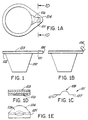
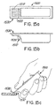
- Fig. 1 we have a side plan view of the first embodiment of the present invention showing a generally frusto-conical bucket shaped dispensing container 100 made of a frangible plastic (HIPS) with a containment formation in which coffee cream or other low viscosity product is held.
- the container 100 has a flat rim 102 encircling said containment formation a portion of which extends outward from said containment formation, to form a tab 104.
- a fault line 101 Sealed to the top surface of said rim and tab 104 is a thin plastic membrane like lid 103.
- Fig. 1a we have a top plan view of the container 100 showing a tongue shaped unsealed area 106 indicated by cross hatching between said lid 103 and said rim 102 and tab 104 where the unsealed area 106 crosses over and slightly beyond the fault line traversed the underside of the tab. It also indicates a section 1D-1D through the fault line which is shown in Fig 1D. showing a central unsealed area 106 between two sealed areas indicated by small x's.
- Fig. 1B shows a side plan view of the dispensing container with the tab 109 bent back rupturing the fault line ready to dispense the product.
- Fig. 1C indicates the fault line configuration having a straight section 107 at each end and a curved arcuate section 108 between said straight sections 107.
- Fig. 1E shows the cross section of the outlet created with the tab 104 bent back showing the arc 109 created by the rupturing of the arcuate section 108 of the fault line 101.
- the film from which the product containing member or bucket may be made of may be on the order of 254 ⁇ m (10 mils) thick and the lid may be a simple monolayer of 25.4 to 50.8 ⁇ m (1 to 2 mil) HIPS with no additional layer required.
- An outer coating of Saran (PvDc) might in some cases be desirable and may be applied during the printing process and add very slightly to the cost of the lid.
- packages made of frangible plastic films such as HIPS don't require stress concentrating protrusions to cause a fault line to rupture thus the terms, groove and micro-groove, are used to describe these formations even though they may protrude on the fault line side of the tab extension. It will also be understood that a somewhat deeper channel can be made with a protrusion projecting from the underside of the tab but it may leak if low viscosity liquid is contained and it's accidentally tipped over.
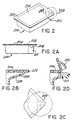
- Fig. 2 shows an isometric drawing of a rectangular embodiment of the instant invention which is of rectangular configuration with one flattened corner 201.
- Figs. 2A-2C show a rim 202 above flatted corner 201 which continues beyond the flat to create a tab, in which is formed a semi-pyramidal beaklike hollow stress concentrator protrusion 208 said tab and protrusion traversed by a fault line 209 parallel to the flattened corner 201.
- the protrusion intersects the narrow wall created by the flattened corner 201.
- the rectangular hollow product containment member 203 with flatted corner 201 has a rim 202 to which is sealed a lid 204.
- Fig. 2D shows the stress concentrator protrusion in bent back position having ruptured said fault line 209 creating product outlet 210.
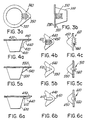
- FIGs. 3A and 3B there are shown a typical container according to another embodiment of the present invention.
- the container comprises a containment member 300 with rim 320 and tab 350 extending therefrom and at least one channel shaped protrusion 310 formed into the rim 320.
- a thin plastic membrane like lid 330 is sealed to the top surface of the rim 320 thereby sealing the container.
- the channel shaped protrusion 310 is formed in the wall of the containment member 300 and curves into the underside of the tab 350.
- a fault line 340 traverses the protrusion 310.
- Figs. 4A and 4B show one embodiment of the present invention utilizing at least one curvilinear channel shaped protrusion 410 formed into the wall of a containment member 400 extending upward and curving into the tab 450.
- a substantially straight fault line 440 traverse the protrusion member 410.
- the fault line 440 ruptures, thereby creating an aperture 460.
- the aperture 460 is particularly suited for high viscosity products and/or particulates, such as salad dressing, ointments, sour cream, and yogurt.
- barrier and high strength materials such as NY-PET-EVOH-PVC-PP, and various coextrusions of such materials as well as HIPS.
- a semi-pyramidal beak shaped protrusion with a peaked cross section traversed by a fault line may be used with a variety of materials ranging from HIPS to the toughest coextrusion of barrier films. It is similar in configuration to one half the stress concentrators claimed on US Patent No. 4,493,574 and will dispense a broad range of products over almost all viscosity ranges.
- Fig. 5a shows a container according to this embodiment of the present invention having a containment member 500 with a semi-pyramidal beak shaped protrusion 510.
- the protrusion 510 extends into a tab 550 and is traversed by a fault line 540.
- the tab 550 is bent back, thereby rupturing the fault line 540.
- rupturing the fault line 540 creates an aperture 560 that is particularly suited for dispensing high viscosity products without particulates, such as suntan lotion, syrup, and the like.
- such a configuration may be made with many high strength and barrier materials such as NY-PET-PVC-EVOH.
- a micro-groove with a fault line traversing its locus may be used.
- the micro-groove may be defined as a groove in the top surface of the tab extension to a depth of less than the thickness of the plastic material of said tab extension.
- a 203 ⁇ m (8 mil (.008")) thick tab extension would have a groove depth of no more than 203 ⁇ m (.008") although in practice 127 ⁇ m (.005") might be preferable.
- These minute micro-grooves are effective channels for the flow of low viscosity products such as coffee cream, alcohol, water, solvents, etc. where flow control is necessary or preferable.
- micro-grooves can, in some cases, be made in the tab extension upper surface with no protrusion on its underside. It will be further realized that if a 254 ⁇ m (10 mil (.010")) groove depth were desired in a 254 ⁇ m (10 mil) thick tab extension then obviously a protrusion would have to appear on its underside. It would however, have no function as a stress concentrator.
- Fig. 6a shows an embodiment of the present invention having one such relatively thin micro groove protrusion 610 formed in a containment member 600.
- micro groove protrusion 610 it is traversed by a fault line 640.
- the micro groove protrusion 610 extends into a tab 650, which when bent back, causes the fault line 640 to rupture, thereby creating an aperture 660.
- the aperture 660 shown in Fig. 6C, is particularly suited for low viscosity products, such as coffee creamers. It is to be appreciated that such a configuration may be made with HIPS and HIPS with laminates through which laminate fault line 640 is cut so that only the HIP is required to rupture when the tab 650 is bent back.
- the outlet forming means about to be described will act as its own valve which will only dispense the product under pressure and then close to prevent even the slightest spill or drip.
- the flat rim extension or tab of a typical bucket shaped coffee creamer takes an approximately triangular configuration and is traversed by a fault line or cut on its underside parallel to a line tangent to the circular creamer body and its entire upper surface is sealed to a lid. Instead of sealing the entire upper tab surface to the lid however a tongue shaped area of the surface of the tab is left unsealed and extends within its peripheral seals from the bucket outward, traversing and carrying slightly beyond the locus of the fault line.
- HIPS frangible plastics
- FIG. 7A-C another embodiment of the present invention is shown having a containment member 700 and the micro groove protrusion 710 formed on the underside tab 750.
- the micro groove protrusion 710 is not traversed by a fault line. Rather, a fault line 740 traverses an unsealed tongue area 712.
- bending back the tab 750 causes the fault line 740 to rupture. Consequently, an unsealed area 760 is exposed, so that slight pressure on the containment member 700 cause the contains therein to be expelled.
- this configuration provides a valve like action and prevents leakage.
- This configuration may be made with HIPS and HIPS with laminates though which laminate the fault line 740 is cut so that only the HIPS is required to rupture.
- Figs. 8A-C another embodiment of the present invention similar to those described in Figs. 4-7, except the embodiment of Fig. 8 does not have a groove or protrusion member. Instead, the container of Fig. 8 is provided with an unsealed tongue shaped area 812 that extends into a tab 850. A fault line 840 traverses the unsealed tongue area shaped 812. When the fault line 840 is ruptured, the rim seal remains surrounding the unsealed area. Upon applying pressure to the containment member 800, an unsealed outlet opening 860 shown in Fig. 8C, is created. Like the previous embodiment, this configuration may be made with HIPS and HIPS with laminates.
- outlet forming means there is no formation made in the tab but it will still have a fault line traversing its underside.
- a hollow formation will be made in the lid which will stand clear of the tab although sealed all around its periphery to act as clearance for the fluid to be dispensed, it may be narrow or not, so long as a portion of it traverses the fault line locus and extends back over the product containment member to provide a channel to the outlet formed when the tab is bent up.
- Figs 9A-C shows such another version having a containment member 900 and no protrusion.
- the embodiment includes a raised formation 914 in the lid.
- the raised formation extends from above the containment member 900 and into a tab 950.
- the fault line 940 traverses the tab 950 under the raised the formation 914.
- rupturing the fault line 940 permits the raised formation 914 to serve as a channel from the containment member 900 to an opening 960 thus formed at the fault line 940.
- the shape of the fault line 940 may be relatively straight, curvilinear, or a combination.
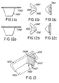
- Fig. 10A-C shows a embodiment similar to Fig. 8A-C and that contains an unsealed tongue area 1012 extending into a tab 1015. Unlike the embodiment of Figs. 8A-C, however, the unsealed tongue area 1012 is traversed by a curvilinear fault line 1040 comprising two straight end sections and a center section arched in a outward direction from the containment member 1000.
- Figs. 11A-C shows the same arrangement as in Figs 10A-C, except that the cross hatching of the unsealed tongue portion 1012 has been removed for clarity.
- Figs. 12A-C show another embodiment of the present invention wherein the fault line 1240 is fully curved. As can best be seen in Fig. 12B the fully curved fault 1240 traverses an unsealed tongue shaped area 1212.
- the system of creating outlet means in the subject packages by simply bending the tab upward has variations other than those embodiments mentioned above.
- These methods in general require a hollow formation, groove or protrusion formed in the tab extending from the underside of the tab and intersecting the hollow product containing portion wall which is traversed by fault line.
- These protrusions may take a variety of configurations and some are particularly advantageous when utilizing tough barrier non-frangible thermoplastic and/or combinations thereof in laminates or coextrusion and/or for handling viscous products or products containing particulates, a variety of stress-concentrating formations may be formed in the rim extension tab of a thermoformed dispenser package.
- these multiple channel shaped protrusions may be in the case of rectangular packages be formed in a tab extending from one entire end of the package as well as from a flattened corner. Such embodiments will now be described in greater detail with reference to Figures 13-16.
- Fig. 13 shows an underside isometric drawing of a generally rectangular shaped package with a flattened corner 1400 where a multiple channel aperture forming means 1440 is formed into a flattened corner 1400 where the width of the aperture forming means 1440 is so great that the flattened corner 1400 becomes the end of the hollow product container member 1405.
- the multi-channel or multi-grooved curvilinear aperture forming means 1440 is shown having the cross section shown in Figure 14C with pointed peaks 1443 and pointed troughs 1442A with a fault line traversing the curved transitional portion of the aperture forming means 1440 which when ruptured will create an extra large outlet.
- the aperture forming means 1440 is formed in rim 1415 to create an enlarged corner tab 1430.
- Figures 14A through 14F illustrate various alternatives of the aperture forming means 1440 of Figure 13. More specifically, Figures 14A through 14F illustrate various cross sectional depictions of the aperture forming means 1440 taken along the fault line.
- the aperture forming means 1440 has multiple channel protrusions 1441 that may have rounded bottoms 1442 in order to prevent inadvertent rupture of the members 1441.
- the aperture forming means protrusions 1441 may have sharp crests or peaks 1443 as shown in Figure 14A, or curved crests 1443A, as shown in Figure 14B.
- both the crests 1443 and the bottoms 1442A may be sharp, as shown in Figure 14C.
- the aperture forming means protrusion 1441 may extend a distance B from the wall flattened corner 1440 of the container 1400.
- the aperture forming means protrusions 1441 may be recessed a distance B from the wall of the container member 1405.
- the distance between protrusion members D, as well as the depth of the protrusion members C, may vary depending upon the material used, its thickness, and the product to be dispensed.
- guard protrusion members 1444 are larger than and extend further than the remaining protrusions 1441, thereby providing more support and greater resistance to inadvertent or even intended opening.
- an aperture forming means 1440 comprises a single "V" shaped channel. It is to be understood that many combinations of the aperture forming means and protrusion members herein discussed may be employed in combination with any sized or shaped container and with various plastic materials of various thicknesses.
- a container 1500 is generally rectangular shaped and has a curvilinear stress concentrator aperture forming means 1510.
- the aperture forming means 1510 is similar to that depicted in Figure 13, it should be noted that in the present embodiment, the aperture forming means 1510 is formed into an end rim extension 1530 curving down the front of the containment member of the container 1500, rather than in a flattened corner.
- a fault line 1520 traverses the aperture forming means 1510.
- Figure 15C depicts the container 1500 in use. As can be seen, the fault line 1520 has been ruptured by bending back the end 1530. Because the container 1500 may be made narrow, it is easily grasped in one hand for dispensing the contents thereof.
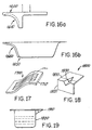
- Figures 16a and 16b show one mechanism for forming the container of Figures 15A-C.
- Figure 16A shows a male forming punch 1600 having a curvilinear front surface 1610.
- the curvilinear front surface 1610 includes a series of grooves and ridges.
- a mating female forming die 1650 has a curvilinear front surface 1660 having a series of grooves and ridges that are complimentary to those of in the front surface 1610 of the male forming punch 1600.
- the material from which a container is to be formed is placed between the male punch 1600 and the female punch 1650. Because the two front surfaces 1610, 1660 are complimentary, they meet in mating engagement, thereby deforming the material into a curvilinear stress concentrator. It is to be understood that any of the stress concentrator aperture forming means described with reference to Figures 14A-F may be obtained by so configuring the front surfaces 1610, 1660.
- a curvilinear (not “generally planar") configuration for the general shape of the aperture forming means worked extremely well particularly when applied in the shape of a shallow inverted:"L" or “hockey stick” to a container with a rim or tab extension.
- the aperture forming means is formed into and beneath the rim or tab extension of the container and traveling toward the container wall and curving downward and formed into said wall. It was found that the shape and size of the aperture could be varied by the location of the traversing fault line and it was further found that the structure of the container wall was considerably strengthened and that wider than expected apertures could be made. It will be seen that a curvilinear formation made independent of a container may be adhesively or sealing attached to various matchingly curved surfaces of containers or other structures.
- Figure 17 shows such an embodiment of the present invention. Specifically, Figure 17 shows an independent curvilinear expandable aperture forming means 1700. Like the aperture forming means described above, a fault line 1720 traverses the aperture forming means 1700.
- the aperture forming means 1700 is formed in a curvilinear base 1710 having virtually any shape, thereby allowing the aperture forming means 1700 to be mounted on any matching curved surface. As noted above, the aperture forming means 1700 is mounted over an opening in a container surface in any number of ways, including placing an adhesive around the perimeter of the base 1710.
- Fig. 18 shows an isometric view of a semi-pyramidal beak like stress concentrator 1800.
- the stress concentrator 1800 may be formed into surfaces having many shapes, the stress concentrator 1800 of the present embodiment depicts is depicted as being formed in two relatively flat walls 1810, 1820.
- the stress concentrator 1800 is hollow and open to the rear (not shown) so that it may be affixed to a containment member, thereby creating a container similar to that shown in Figs. 5a-c.
- the semi-pyramidal beak like stress concentrator member 1800 is traversed by a fault line 1830. It is to be understood that like the embodiment shown in Fig. 17, the semi-pyramidal beak like protrusion may be formed in a curvilinear base as well.
- Some of the easy opening features may be formed independently and sealed or adhered to inner or outer surfaces of many packages such as bags, milk containers, pouches pillow packages (sachets), etc. to make for very efficient low cost dispensing packages or squeeze bags.
- These squeeze bag type packages could dispense food pastes such as pet food, etc. cremes, grease, yogurt, certain types of dough, cake frosting and could be made of everything from treated, coated paperboard, plastic films, foils, laminates or coextrusion of these materials.
- Fig. 19 shows such a structure having a relatively stiff rim 1910 and a soft containment member 1920. It should be also understood that this structure can be capable of standing upright and in fact resist tipping over somewhat in the manner of bean bag.
Landscapes
- Closures For Containers (AREA)
- Packages (AREA)
Claims (17)
- Dünnwandiger Behälter (100), der aus einem verhältnismäßig dünnen, flachen Kunststofffilm durch Wärmebehandlung gebildet ist und eine hohle Behältnisform mit einer Basis parallel zu einem oberen, flachen Rand (102) aufweist, an dem ein dünnes Deckelelement (103) in einem Abdichtungsmuster abdichtend befestigt oder angeschweißt ist, wobei der Dichtungsrand die Behältnisform mit wenigstens einem Teil des Dichtungsrandes (102) umgibt, der sich von der hohlen Behältnisform um einen Betrag nach außen erstreckt, der ausreichend ist, um es zu ermöglichen, daß er als Lasche (104) funktioniert, wobei der vorstehende Laschenabschnitt (104) eine Bruchlinie (102) hat, die sich über die Lasche (104) unter einem rechten Winkel zu einer Mittellinie erstreckt, die sich von der hohlen Behältnisform nach außen erstreckt und die, wenn der Laschenabschnitt nach oben gebogen wird, bewirkt, daß die Lasche (104) an der Bruchlinie (101) abbricht, so daß bewirkt wird, daß der äußere Laschenabschnitt (104) von dem restlichen Laschenabschnitt (104) abbricht, während er mit dem dünnen Deckelelement abdichtend verbunden oder verschweißt bleibt, der ebenfalls nach oben gebogen wird, um eine Auslaßmündung für fließfähiges Material zwischen dem verbleibenden Laschenabschnitt und dem dünnen Deckel (103) zu erzeugen, dadurch gekennzeichnet, daß die Bruchlinie in die Unterseite der Lasche eingeschnitten ist.
- Behälter (100) nach Anspruch 1, worin die aufrecht stehende, hohle Behältnisform eine allgemein kegelstumpfförmige Becherform ist.
- Behälter (100) nach Anspurch 1 oder Anspruch 2, worin das Abdichtungsmuster einen nicht-abgedichteten, zungenförmigen Bereich zwischen dem Rand (102) und seinem Laschenabschnitt (104) und dem dünnen Deckel (103) erzeugt, wobei der nicht abgedichtete, zungenförmige Bereich von einer um den Umfang des Zungenbereichs (104) und seinen Fortsatz verlaufende Deckelabdichtung an dem Rand (102) umfasst wird, wobei sich der nicht abgedichtete Bereich von der hohlen Behältnisform nach außen erstreckt, über die Lasche (104) und die Bruchlinie (102) auf der Unterseite der Lasche verläuft und an der umfangsmässigen Deckelabdichtung endet.
- Behälter nach Anspruch 3, worin die Bruchlinie (101) gerade ist.
- Behälter nach Anspruch 3, worin die Bruchlinie (101) kurvenförmig ist, wobei ihre konvexe Seite von der Behältnisform weg gerichtet ist.
- Behälter (100) nach Anspruch 3, worin die Bruchlinie (101) einen geraden Abschnitt an jedem Ende und einen kurvenförmigen Abschnitt zwischen den geraden Abschnitten hat, wobei der kurvenförmige Abschnitt über den nicht-abgedichteten, zungenförmigen Bereich verläuft, wobei es seine konvexe Seite von der Behältnisform weg gerichtet ist.
- Behälter (100) nach Anspruch 1, worin die vorstehende Lasche (104) eine Einrichtung (1440) zur Bildung einer eine Streßbeanspruchung konzentrierende Öffnung hat, die wenigstens einen dünnwandigen, kanalförmigen Ansatz aufweist, der von ihrer unteren Oberfläche vorsteht und von der Bruchlinie (101) auf der Unterseite der Lasche (104) überquert wird, wobei der wenigstens eine Ansatz sich von dem Schnitt mit der Seitenwand der hohlen Behältnisform gerade über die quer verlaufende Bruchlinie (101) nach außen erstreckt, wobei der wenigstens eine Ansatz von einer Deckelabdichtung um den Umfang des vorstehenden Laschenbereichs (104) und seinen Fortsatz entlang dem Rand (102) umfasst wird, wobei der wenigstens eine Ansatz kurvenförmig die Seitenwand der hohlen Behältnisform nach unten verläuft, um als Wandverstärkungs-Anschlusselement zu wirken.
- Behälter (100) nach Anspruch 1 oder Anspruch 2, worin der Laschenabschnitt (104) auf seiner Oberseite eine Nut hat, wobei die Nut sich von der Behältnisform nach außen erstreckt, über die Lasche (104) und die Bruchlinie (101) auf der Unterseite der Lasche unter einem rechten Winkel verläuft und gerade jenseits der Bruchlinie (101) endet, um einen Auslass für ein niedrig viskoses Produkt zu erzeugen, wenn der Laschenabschnitt nach oben gebogen wird, um die Bruchlinie (101) zu brechen.
- Behälter (100) nach Anspruch 3, worin die obere Oberfläche des nicht abgedichteten, zungenförmigen Bereiches des Laschenabschnitts einen Kanal hat, der sich von der Behältnisform zu einem Punkt erstreckt, der unter einem kurzen Abstand vor dem Erreichen der Bruchlinie (101) auf der Unterseite der Lasche endet, um einen Ventilauslaß zu erzeugen, wenn der Laschenabschnitt nach oben gebogen wird, um die Bruchlinie (101) zu brechen.
- Behälter (100) nach Anspruch 2, worin der Laschenabschnitt (104) eine Nut auf seiner Oberseite hat, wobei die Nut sich von der Behältnisform nach außen erstreckt, die Lasche (104) und die Bruchlinie (101) auf der Unterseite der Lasche unter einem rechten Winkel überquert und gerade jenseits der Bruchlinie (101) endet, um einen Auslaßkanal für ein niedrig viskoses Produkt zu erzeugen, wenn der Laschenabschnitt (104) nach oben gebogen wird, um die Bruchlinie (101) zu brechen.
- Behälter (100) nach Anspruch 3, 4 oder 5, worin die obere Oberfläche des nicht abgedichteten, zungenförmigen Bereiches des Laschenabschnitts (104) eine Nut hat, die sich von der Behältnisform zu einem Punkt erstreckt, der unter einem kurzen Abstand vor dem Erreichen der Bruchlinie (101) auf der Unterseite der Lasche endet, um einen Ventilauslaß zu erzeugen, wenn der Laschenabschnitt nach oben gebogen wird, um die Bruchlinie (101) zu brechen.
- Behälter (100) nach Anspruch 6, worin die obere Oberfläche des nicht abgedichteten, zungenförmigen Bereiches des Laschenabschnitts (104) eine Mikronut hat, die sich von der Behältnisform zu einem Punkt erstreckt, der unter einem kurzen Abstand vor dem Erreichen der Bruchlinie (101) auf der Unterseite der Lasche endet, um einen Ventilauslaß zu erzeugen, wenn der Laschenabschnitt nach oben gebogen wird, um die Faltlinie (101) zu brechen.
- Behälter (100) nach Anspruch 1, worin der Laschenabschnitt (104) im allgemeinen einen halb-pyramidenförmigen, schnabelartigen, hohlen, eine Streßbelastung konzentrierenden Ansatz (208) hat, der sich von der Lasche (104) nach unten erstreckt und die Seitenwand der Behältnisform mit seinem großen Ende schneidet, wobei der Ansatz von der Bruchlinie (101) auf der Unterseite der Lasche überquert wird, wobei der Ansatz eine solche Form hat, daß er als Verstärkungsansatz zwischen der Lasche (104) und der Wand der Behältnisform wirkt.
- Behälter (100) nach Anspruch 1, worin das hohle Behälterelement einen im allgemeinen rechteckigen Querschnitt hat, wobei eine Ecke abgeflacht ist, wobei die Lasche (104) sich über die abgeflachte Ecke erstreckt.
- Einrichtung zur Erzeugung eines Auslaßes zum Anbringen an einer Abgabeverpakkung für fließfähige Substanzen, die ein dünnes Deckelelement hat, welches abdichtend an einem Umfangsrandabschnitt davon befestigt ist, wobei die einen Auslaß erzeugende Einrichtung umfaßt:wobei das Umbiegen des Endes des im allgemeinen krummlinigen Elements an der Bruchlinie, die die Streßbeanspruchung konzentrierende, öffnungsbildende Einrichtung auslenkt und dadurch das krummlinige Element an der Bruchlinie abbricht, um einen verhältnismäßig flexiblen und ausdehnbaren Öffnungsauslaß zu erzeugen;ein verhältnismäßig steifes, krummliniges Element, welches aus einem im wesentlichen flachen, verhältnismäßig dünnen, relativ flexiblem Material gebildet ist;eine eine Streßbeanspruchung konzentrierende, öffnungsbildende Einrichtung (1700) in dem krummlinigen Element, die wenigstens einen länglichen, dickwandigen, kanalförmigen Ansatz (301) aufweist, der von einer Oberfläche des krummlinigen Elements vorsteht;wobei das krummlinige Element einen im wesentlichen flachen Umfangsrandabschnitt um die eine Streßbeanspruchung konzentrierende, öffnungsbildende Einrichtung (1700) aufweist;wobei das dünne Deckelelement in der Lage ist, abdichtend an dem Umfangsrandabschnitt des krummlinigen Elements befestigt oder verschweißt zu werden; undeine Bruchlinie mit einer vorgegebenen Form und Länge, die über das kanalförmige, eine Streßbeanspruchung konzentrierende Ansatzelement hinweg verläuft;
wobei der abgebrochene Endteil in der Lage ist, mit dem dünnen Deckelelement abgedichtet zu bleiben;
dadurch gekennzeichnet, daß die Bruchlinie eingeschnitten ist. - Ein im allgemeinen halb-pyramidenförmiger, schnabelartiger, hohler, einer Streßbeanspruchung konzentrierender Ansatz (1800), der zum Anfügen an eine Abgabepackung geeignet ist, wird aus einem dünnen, flachen, thermoplastischen Film durch Wärmeeinwirkung gebildet, so daß er sich von dem thermoplastischen Film nach unten erstreckt, dessen großes Ende eine Wand, die gleichzeitig aus dem gleichen flachen Film durch Wärmebehandlung gebildet ist, näherungsweise unter einem rechten Winkel zu dem Film schneidet, wobei ein zweiter, einen flachen Film bildender Teil der Abgabepackung abdichtend an dem halb-pyramidenförmigen, schnabelartigen, hohlen, eine Streßbeanspruchung konzentrierenden Ansatz an dem Umfangsrandabschnitt davon abdichtend befestigt oder verschweißt werden kann, wobei der die Streßbeanspruchung konzentrierende Ansatz quer von der Bruchlinie (1830) an einer vorgegebenen Stelle übergriffen wird, wobei der die Streßbeanspruchung konzentrierende Ansatz (1800) eine solche Form hat, daß er als Verstärkungsansatz zwischen dem zweiten flachen Film und der näherungsweise rechtwinkligen Wand wirkt, dadurch gekennzeichnet, daß die Bruchlinie eingeschnitten ist.
- Behälter nach Anspruch 1, worin die hohle Behältnisform nicht starr mit einem oberen, flachen, relativ steifen Rand ist.
Applications Claiming Priority (8)
| Application Number | Priority Date | Filing Date | Title |
|---|---|---|---|
| US1104396P | 1996-02-02 | 1996-02-02 | |
| US11043P | 1996-02-02 | ||
| US1104P | 1996-02-02 | ||
| US3463397P | 1997-01-03 | 1997-01-03 | |
| US3573797P | 1997-01-03 | 1997-01-03 | |
| US3573P | 1997-01-03 | ||
| US34633P | 1997-01-03 | ||
| PCT/US1997/001458 WO1997028054A1 (en) | 1996-02-02 | 1997-01-31 | Improved coffee creamer and other cups and tubs |
Publications (3)
| Publication Number | Publication Date |
|---|---|
| EP0918697A1 EP0918697A1 (de) | 1999-06-02 |
| EP0918697A4 EP0918697A4 (de) | 2000-04-12 |
| EP0918697B1 true EP0918697B1 (de) | 2003-11-12 |
Family
ID=27359350
Family Applications (1)
| Application Number | Title | Priority Date | Filing Date |
|---|---|---|---|
| EP97905668A Expired - Lifetime EP0918697B1 (de) | 1996-02-02 | 1997-01-31 | Behälter für kaffeesahne sowie sonstige becher und wannen |
Country Status (1)
| Country | Link |
|---|---|
| EP (1) | EP0918697B1 (de) |
Cited By (1)
| Publication number | Priority date | Publication date | Assignee | Title |
|---|---|---|---|---|
| WO2007118649A1 (de) * | 2006-04-13 | 2007-10-25 | Cfs Kempten Gmbh | Eine mikrowellengeeignete verpackung |
Family Cites Families (5)
| Publication number | Priority date | Publication date | Assignee | Title |
|---|---|---|---|---|
| DE2155069A1 (de) * | 1971-11-05 | 1973-05-10 | Gundermann Unionpack | Verpackungsbehaelter fuer fluessige und pastoese stoffe |
| DE2232861A1 (de) * | 1972-07-05 | 1974-01-17 | Bosch Verpackungsmaschinen | Blisterpackung |
| US4724982A (en) * | 1986-12-18 | 1988-02-16 | Sanford Redmond | Asymmetric stress concentrator for a dispenser package |
| NL8701701A (nl) * | 1987-07-17 | 1989-02-16 | Heijenga S Management B V | Houder voor een geringe hoeveelheid melk, room of dergelijke. |
| EP0332885A1 (de) * | 1988-03-17 | 1989-09-20 | Societe Des Produits Nestle S.A. | Wiederverschliessbarer Behälter aus Kunststoff |
-
1997
- 1997-01-31 EP EP97905668A patent/EP0918697B1/de not_active Expired - Lifetime
Cited By (1)
| Publication number | Priority date | Publication date | Assignee | Title |
|---|---|---|---|---|
| WO2007118649A1 (de) * | 2006-04-13 | 2007-10-25 | Cfs Kempten Gmbh | Eine mikrowellengeeignete verpackung |
Also Published As
| Publication number | Publication date |
|---|---|
| EP0918697A1 (de) | 1999-06-02 |
| EP0918697A4 (de) | 2000-04-12 |
Similar Documents
| Publication | Publication Date | Title |
|---|---|---|
| US6085942A (en) | Coffee creamer and other cups and tubs | |
| CA2390907C (en) | Sealed containment and dispensing package with outlet forming structure | |
| US6651848B1 (en) | Tubelike dispenser package | |
| US6062413A (en) | Reclosable dispenser package, reclosable outlet forming structure and method and apparatus for making same | |
| AU661109B2 (en) | Stress concentrator aperture-forming means for sealed containers and packages | |
| US6299012B1 (en) | Reclosable dispenser package, reclosable outlet forming structure and method and apparatus for making same | |
| AU726529B2 (en) | Improved coffee creamer and other cups and tubs | |
| AP925A (en) | Reclosable dispenser package, reclosable outlet forming structure and method and apparatus for making same. | |
| EP0918697B1 (de) | Behälter für kaffeesahne sowie sonstige becher und wannen | |
| HK1019431B (en) | Improved coffee creamer and other cups and tubs |
Legal Events
| Date | Code | Title | Description |
|---|---|---|---|
| PUAI | Public reference made under article 153(3) epc to a published international application that has entered the european phase |
Free format text: ORIGINAL CODE: 0009012 |
|
| 17P | Request for examination filed |
Effective date: 19980731 |
|
| AK | Designated contracting states |
Kind code of ref document: A1 Designated state(s): AT BE CH DE DK ES FI FR GB GR IE IT LI LU MC NL PT SE |
|
| AX | Request for extension of the european patent |
Free format text: AL PAYMENT 19980731;LT PAYMENT 19980731;LV PAYMENT 19980731;RO PAYMENT 19980731;SI PAYMENT 19980731 |
|
| A4 | Supplementary search report drawn up and despatched |
Effective date: 20000229 |
|
| AK | Designated contracting states |
Kind code of ref document: A4 Designated state(s): AT BE CH DE DK ES FI FR GB GR IE IT LI LU MC NL PT SE |
|
| RIC1 | Information provided on ipc code assigned before grant |
Free format text: 7B 65D 35/08 A, 7B 65D 17/00 B, 7B 65D 75/58 B, 7B 65D 77/20 B, 7B 65D 77/30 B |
|
| 17Q | First examination report despatched |
Effective date: 20010314 |
|
| GRAH | Despatch of communication of intention to grant a patent |
Free format text: ORIGINAL CODE: EPIDOS IGRA |
|
| GRAS | Grant fee paid |
Free format text: ORIGINAL CODE: EPIDOSNIGR3 |
|
| GRAA | (expected) grant |
Free format text: ORIGINAL CODE: 0009210 |
|
| AK | Designated contracting states |
Kind code of ref document: B1 Designated state(s): AT BE CH DE DK ES FI FR GB GR IE IT LI LU MC NL PT SE |
|
| AX | Request for extension of the european patent |
Extension state: AL LT LV RO SI |
|
| PG25 | Lapsed in a contracting state [announced via postgrant information from national office to epo] |
Ref country code: FI Free format text: LAPSE BECAUSE OF FAILURE TO SUBMIT A TRANSLATION OF THE DESCRIPTION OR TO PAY THE FEE WITHIN THE PRESCRIBED TIME-LIMIT Effective date: 20031112 Ref country code: AT Free format text: LAPSE BECAUSE OF FAILURE TO SUBMIT A TRANSLATION OF THE DESCRIPTION OR TO PAY THE FEE WITHIN THE PRESCRIBED TIME-LIMIT Effective date: 20031112 |
|
| REG | Reference to a national code |
Ref country code: GB Ref legal event code: FG4D |
|
| REG | Reference to a national code |
Ref country code: CH Ref legal event code: EP |
|
| REG | Reference to a national code |
Ref country code: CH Ref legal event code: NV Representative=s name: KELLER & PARTNER PATENTANWAELTE AG |
|
| REF | Corresponds to: |
Ref document number: 69726155 Country of ref document: DE Date of ref document: 20031218 Kind code of ref document: P |
|
| REG | Reference to a national code |
Ref country code: IE Ref legal event code: FG4D |
|
| PGFP | Annual fee paid to national office [announced via postgrant information from national office to epo] |
Ref country code: SE Payment date: 20040130 Year of fee payment: 8 Ref country code: NL Payment date: 20040130 Year of fee payment: 8 |
|
| PGFP | Annual fee paid to national office [announced via postgrant information from national office to epo] |
Ref country code: DK Payment date: 20040202 Year of fee payment: 8 Ref country code: GR Payment date: 20040202 Year of fee payment: 8 |
|
| PGFP | Annual fee paid to national office [announced via postgrant information from national office to epo] |
Ref country code: GB Payment date: 20040204 Year of fee payment: 8 |
|
| PGFP | Annual fee paid to national office [announced via postgrant information from national office to epo] |
Ref country code: FR Payment date: 20040210 Year of fee payment: 8 |
|
| PG25 | Lapsed in a contracting state [announced via postgrant information from national office to epo] |
Ref country code: SE Free format text: LAPSE BECAUSE OF FAILURE TO SUBMIT A TRANSLATION OF THE DESCRIPTION OR TO PAY THE FEE WITHIN THE PRESCRIBED TIME-LIMIT Effective date: 20040212 Ref country code: GR Free format text: LAPSE BECAUSE OF FAILURE TO SUBMIT A TRANSLATION OF THE DESCRIPTION OR TO PAY THE FEE WITHIN THE PRESCRIBED TIME-LIMIT Effective date: 20040212 Ref country code: DK Free format text: LAPSE BECAUSE OF FAILURE TO SUBMIT A TRANSLATION OF THE DESCRIPTION OR TO PAY THE FEE WITHIN THE PRESCRIBED TIME-LIMIT Effective date: 20040212 |
|
| PGFP | Annual fee paid to national office [announced via postgrant information from national office to epo] |
Ref country code: DE Payment date: 20040212 Year of fee payment: 8 |
|
| PGFP | Annual fee paid to national office [announced via postgrant information from national office to epo] |
Ref country code: LU Payment date: 20040213 Year of fee payment: 8 Ref country code: IE Payment date: 20040213 Year of fee payment: 8 |
|
| PGFP | Annual fee paid to national office [announced via postgrant information from national office to epo] |
Ref country code: ES Payment date: 20040224 Year of fee payment: 8 |
|
| PGFP | Annual fee paid to national office [announced via postgrant information from national office to epo] |
Ref country code: MC Payment date: 20040226 Year of fee payment: 8 |
|
| PGFP | Annual fee paid to national office [announced via postgrant information from national office to epo] |
Ref country code: BE Payment date: 20040409 Year of fee payment: 8 |
|
| LTIE | Lt: invalidation of european patent or patent extension |
Effective date: 20031112 |
|
| REG | Reference to a national code |
Ref country code: ES Ref legal event code: FG2A Ref document number: 2212076 Country of ref document: ES Kind code of ref document: T3 |
|
| ET | Fr: translation filed | ||
| PLBE | No opposition filed within time limit |
Free format text: ORIGINAL CODE: 0009261 |
|
| STAA | Information on the status of an ep patent application or granted ep patent |
Free format text: STATUS: NO OPPOSITION FILED WITHIN TIME LIMIT |
|
| 26N | No opposition filed |
Effective date: 20040813 |
|
| PGFP | Annual fee paid to national office [announced via postgrant information from national office to epo] |
Ref country code: CH Payment date: 20050127 Year of fee payment: 9 |
|
| PG25 | Lapsed in a contracting state [announced via postgrant information from national office to epo] |
Ref country code: MC Free format text: LAPSE BECAUSE OF NON-PAYMENT OF DUE FEES Effective date: 20050131 Ref country code: LU Free format text: LAPSE BECAUSE OF NON-PAYMENT OF DUE FEES Effective date: 20050131 Ref country code: IT Free format text: LAPSE BECAUSE OF NON-PAYMENT OF DUE FEES;WARNING: LAPSES OF ITALIAN PATENTS WITH EFFECTIVE DATE BEFORE 2007 MAY HAVE OCCURRED AT ANY TIME BEFORE 2007. THE CORRECT EFFECTIVE DATE MAY BE DIFFERENT FROM THE ONE RECORDED. Effective date: 20050131 Ref country code: IE Free format text: LAPSE BECAUSE OF NON-PAYMENT OF DUE FEES Effective date: 20050131 Ref country code: GB Free format text: LAPSE BECAUSE OF NON-PAYMENT OF DUE FEES Effective date: 20050131 Ref country code: BE Free format text: LAPSE BECAUSE OF NON-PAYMENT OF DUE FEES Effective date: 20050131 |
|
| PG25 | Lapsed in a contracting state [announced via postgrant information from national office to epo] |
Ref country code: ES Free format text: LAPSE BECAUSE OF NON-PAYMENT OF DUE FEES Effective date: 20050201 |
|
| BERE | Be: lapsed |
Owner name: *REDMOND SANFORD Effective date: 20050131 |
|
| PG25 | Lapsed in a contracting state [announced via postgrant information from national office to epo] |
Ref country code: NL Free format text: LAPSE BECAUSE OF NON-PAYMENT OF DUE FEES Effective date: 20050801 |
|
| PG25 | Lapsed in a contracting state [announced via postgrant information from national office to epo] |
Ref country code: DE Free format text: LAPSE BECAUSE OF NON-PAYMENT OF DUE FEES Effective date: 20050802 |
|
| GBPC | Gb: european patent ceased through non-payment of renewal fee |
Effective date: 20050131 |
|
| PG25 | Lapsed in a contracting state [announced via postgrant information from national office to epo] |
Ref country code: FR Free format text: LAPSE BECAUSE OF NON-PAYMENT OF DUE FEES Effective date: 20050930 |
|
| NLV4 | Nl: lapsed or anulled due to non-payment of the annual fee |
Effective date: 20050801 |
|
| REG | Reference to a national code |
Ref country code: IE Ref legal event code: MM4A |
|
| REG | Reference to a national code |
Ref country code: FR Ref legal event code: ST |
|
| PG25 | Lapsed in a contracting state [announced via postgrant information from national office to epo] |
Ref country code: LI Free format text: LAPSE BECAUSE OF NON-PAYMENT OF DUE FEES Effective date: 20060131 Ref country code: CH Free format text: LAPSE BECAUSE OF NON-PAYMENT OF DUE FEES Effective date: 20060131 |
|
| REG | Reference to a national code |
Ref country code: ES Ref legal event code: FD2A Effective date: 20050201 |
|
| REG | Reference to a national code |
Ref country code: CH Ref legal event code: PL |
|
| BERE | Be: lapsed |
Owner name: *REDMOND SANFORD Effective date: 20050131 |
|
| PG25 | Lapsed in a contracting state [announced via postgrant information from national office to epo] |
Ref country code: PT Free format text: LAPSE BECAUSE OF NON-PAYMENT OF DUE FEES Effective date: 20040412 |