EP0917384A2 - Verfahren zum Betreiben einer Kommunikationsanlage - Google Patents
Verfahren zum Betreiben einer Kommunikationsanlage Download PDFInfo
- Publication number
- EP0917384A2 EP0917384A2 EP98114844A EP98114844A EP0917384A2 EP 0917384 A2 EP0917384 A2 EP 0917384A2 EP 98114844 A EP98114844 A EP 98114844A EP 98114844 A EP98114844 A EP 98114844A EP 0917384 A2 EP0917384 A2 EP 0917384A2
- Authority
- EP
- European Patent Office
- Prior art keywords
- connection
- unit
- connection unit
- switching unit
- transition
- Prior art date
- Legal status (The legal status is an assumption and is not a legal conclusion. Google has not performed a legal analysis and makes no representation as to the accuracy of the status listed.)
- Withdrawn
Links
- 238000004891 communication Methods 0.000 title claims description 22
- 238000000034 method Methods 0.000 title claims description 9
- 230000007704 transition Effects 0.000 claims description 28
- 230000005540 biological transmission Effects 0.000 claims description 17
- 238000012546 transfer Methods 0.000 claims description 6
- 230000001960 triggered effect Effects 0.000 claims description 3
- 238000010586 diagram Methods 0.000 description 2
- 238000006243 chemical reaction Methods 0.000 description 1
- 238000013461 design Methods 0.000 description 1
- 238000011161 development Methods 0.000 description 1
- 238000009472 formulation Methods 0.000 description 1
- 238000005259 measurement Methods 0.000 description 1
- 239000000203 mixture Substances 0.000 description 1
- 238000000926 separation method Methods 0.000 description 1
Images

Classifications
-
- H—ELECTRICITY
- H04—ELECTRIC COMMUNICATION TECHNIQUE
- H04W—WIRELESS COMMUNICATION NETWORKS
- H04W36/00—Hand-off or reselection arrangements
- H04W36/08—Reselecting an access point
Definitions
- the invention relates to a method for operating a Communication system in which a connection from one mobile terminal via a first connection unit to a Switching unit and from there via an associated one Connection unit is built to another terminal. Furthermore, the invention relates to a Communication system that has at least two connection units has at least one mobile and another Terminal are connected, a connection from the mobile terminal via the first connection unit to a Switching unit and from there via the associated Connection unit to be built to the other terminal can.
- Such a communication system is, for example, out known in the area of private telephone networks as they among others in hospitals etc. be used.
- connection units Communication system There is e.g. one of the connection units Communication system a corded phone connected while using another connector unit the base station of a cordless phone is connected. About the two connection units and the switching unit of the Communication system can then establish a connection between the both phones can be set up.
- a plurality can be connected to such a communication system of connection units and thus a plurality of Base stations connected for cordless phones become. This makes it possible to use the base stations in the To distribute hospital so that each cordless Telephone at any moment with one of the base stations can communicate. So a user is one of those cordless phones not only in the transmission / reception area a base station, but in a larger local Area accessible at all times.
- the object of the invention is to provide a communication system create such a transition from the first to provides a second connection unit.
- This task is initiated in a procedure mentioned type or in a communication system of type mentioned solved in that the connection from the switching unit to the first connection unit disconnected and a connection from the switching unit to the second connection unit is built.
- the transition from the first to the second connection unit does not take place in the switching unit or in one of the Connection units, but in between in one Relay unit. From this the connection between the switching unit and the first connection unit separated in order to then proceed from this separation to establish a new connection to the second connection unit.
- This procedure has the advantage that the switching unit with the transition from the first to the second Connection unit is not loaded.
- the switching unit can thus be constructed and used in a modular manner without pay attention to possible transitions between connection units should be.
- connection units with the Transition as such not burdened.
- the connection units can therefore also be modular and be used.
- the transition is from that between the line units and the switching unit arranged relay unit carried out.
- the transfer unit must be not actually exist, but will usually as a logical functional sequence, for example in the form of a program on a computing device be realized.
- the transfer unit manages the Disconnection of the existing connection and the establishment of the new connection characterized in that the switch unit no longer passed information to the first Connection unit can be addressed, but to the second Connector unit, and vice versa.
- connection to the first connection unit disconnected and the connection to the second connection unit is built up without the Switching unit is affected. In this way there are no changes for the switching unit due to the transition from the first to the second Connection unit. So for the switching unit is permanent simulates a state as if no transition from the would have taken place first on the second connection unit.
- the first and the second connection unit each one Have transmission / reception area within which one Connection to the mobile device can be established becomes the connection to the first connection unit disconnected and the connection to the second Connection unit built when the mobile terminal Transmit / receive area of the first connection unit leaves and in the transmission / reception area of the second Connection unit enters.
- the Forwarding unit can choose the transition and through design appropriate measures so that in each If the connection to the second connection unit is accurate starts where the connection with the first Connection unit has ended.
- the entry of the mobile device into the transmission / reception area reported to the second connection unit and it will then be the transition from the first to the second Connection unit triggered.
- the message is sent to the Forwarding unit transmitted, so that after that Transfer unit the transition from the first to the can trigger second connection unit.
- connection to the second connection unit is better than the first connection unit. To this ensures that the better connection is always between the switching unit and the mobile terminal is available.
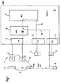
- ICU interface control unit
- DECT digital enhanced Certainly each of the Connection units 2, 3, 4 can be a terminal or several end devices can be connected.
- connection unit 2 Base stations 5 connected. These base stations 5 Cordless phones 6 can be assigned. This means that a connection can be established between each of the base stations 5 and each of the phones 6. A transition of a connection between one of the Phones 6 and one of the base stations 5 to one Connection of the same telephone 6 to another Base station 5 is known to be during one Call possible, provided that it is only to the Connection unit 2 connected base stations 5 is.
- connection unit 3 At the connection unit 3 is a terminal corded telephone 7 connected. Furthermore is to the connection unit 4 as a terminal Base station 8 connected for a cordless phone.
- MBU mobility unit
- MSU module switching unit
- the Connection units 2, 3, 4, the relay unit 10 and the Switching unit 11 form a module 12 (module_1) Communication system 1.
- a connection between the one with the reference number "A" marked corded phone 7 and with the Reference number "B" marked cordless telephone 6 is done by first connecting the cordless phone 6 to one of the base stations 5 and from is set up there to the connection unit 2. Then the Connection via the relay unit 10 to the Switching unit 11 continued. From the switching unit 11 finally a connection to the connection unit 3 and from there to the corded telephone 7.
- Each of the base stations 5, 8 has a transmission / reception area on where one of the cordless phones 6 can communicate with the respective base station 5, 8. This range is, for example, about 50 meters to about 300 meters.
- the base station 8 reports the entry of the cordless Telephone 6 "B '" to the associated connection unit 4 and the latter sends this message to the forwarding unit 10 further.
- the relay unit 10 checks to which of the two base stations 5, 8 a better connection to that cordless phone 6 "B '" exists. This can be due to Field strength measurements or the like especially from the Base stations 5, 8 are carried out.
- the relay unit 10 separates the Connection between the associated to the base stations 5 Connection unit 2 and the switching unit 11.
- the relay unit 10 establishes a connection from the switching unit 11 to that to the base station 8 associated connection unit 4.
- a connection between the one with the reference number "A" marked corded phone 7 and with the Reference number "B" marked cordless telephone 6 is done by first connecting the cordless telephone 6 to the connection unit 2 becomes. Then the connection is made via the relay unit 10 to the switching unit 11 and from there to the Switching unit 18 continued. From the switching unit 18 finally a connection to the connection unit 3 and from there to the corded telephone 7.
- the relay unit 10 of the first module 12 separates now the connection between the connection unit 2 and the switching unit 11. At the same time, the Forwarding unit 10 a connection from the switching unit 11 to the connection unit 4. This connection is made thereby via the relay unit 10 of the first module 12 and via the relay unit 17 of the second module 19.
Landscapes
- Engineering & Computer Science (AREA)
- Computer Networks & Wireless Communication (AREA)
- Signal Processing (AREA)
- Mobile Radio Communication Systems (AREA)
Abstract
Description
- Figur 1
- zeigt eine schematische Blockdarstellung eines ersten Ausführungsbeispiels einer erfindungsgemäßen Kommunikationsanlage, und
- Figur 2
- zeigt eine schematische Blockdarstellung eines zweiten Ausführungsbeispiels einer erfindungsgemäßen Kommunikationsanlage.
Claims (9)
- Verfahren zum Betreiben einer Kommunikationsanlage (1), bei dem eine Verbindung von einem mobilen Endgerät (B) über eine erste Anschlußeinheit (2) zu einer Schalteinheit (11) und von dort über eine zugehörige Anschlußeinheit (3) zu einem weiteren Endgerät (A) aufgebaut wird, dadurch gekennzeichnet, daß die Verbindung von der Schalteinheit (11) zu der ersten Anschlußeinheit (2) aufgetrennt und eine Verbindung von der Schalteinheit (11) zu einer zweiten Anschlußeinheit (4) aufgebaut wird.
- Verfahren nach Anspruch 1, dadurch gekennzeichnet, daß die Verbindung zu der ersten Anschlußeinheit (2) aufgetrennt und die Verbindung zu der zweiten Anschlußeinheit (4) aufgebaut wird, ohne daß die Schalteinheit (11) dadurch beeinflußt wird.
- Verfahren nach einem der Ansprüche 1 oder 2, wobei die erste und die zweite Anschlußeinheit (2, 4) jeweils einen Sende-/Empfangsbereich aufweisen, innerhalb dem eine Verbindung zu dem mobilen Endgerät (B) aufgebaut werden kann, dadurch gekennzeichnet, daß die Verbindung zu der ersten Anschlußeinheit (2) aufgetrennt und die Verbindung zu der zweiten Anschlußeinheit (4) aufgebaut wird, wenn das mobile Endgerät (B) den Sende-/Empfangsbereich der ersten Anschlußeinheit (2) verläßt und in den Sende-/Empfangsbereich der zweiten Anschlußeinheit (4) eintritt.
- Verfahren nach Anspruch 3, dadurch gekennzeichnet, daß das Eintreten des mobilen Endgeräts (B') in den Sende-/Empfangsbereich der zweiten Anschlußeinheit (4) gemeldet wird, und daß danach der Übergang von der ersten auf die zweite Anschlußeinheit (2, 4) ausgelöst wird.
- Verfahren nach Anspruch 4, dadurch gekennzeichnet, daß der Übergang durchgeführt wird, wenn die Verbindung zu der zweiten Anschlußeinheit (4) besser ist als zu der ersten Anschlußeinheit (2).
- Kommunikationsanlage (1), die mindestens zwei Anschlußeinheiten (2, 3, 4) aufweist, an die mindestens ein mobiles und ein weiteres Endgerät (B, A) angeschlossen sind, wobei eine Verbindung von dem mobilen Endgerät (B) über die erste Anschlußeinheit (2) zu einer Schalteinheit (11) und von dort über die zugehörige Anschlußeinheit (3) zu dem weiteren Endgerät (A) aufgebaut werden kann, dadurch gekennzeichnet, daß zwischen der ersten Anschlußeinheit (2) und der Schalteinheit (11) eine Weitergabeeinheit (10) vorgesehen ist, die die Verbindung von der Schalteinheit (11) zu der ersten Anschlußeinheit (2) auftrennen und eine Verbindung von der Schalteinheit (11) zu einer zweiten Anschlußeinheit (4) aufbauen kann.
- Kommunikationsanlage (1) nach Anspruch 6, dadurch gekennzeichnet, daß von der Weitergabeeinheit (10) der Übergang von der ersten Anschlußeinheit (2) auf die zweite Anschlußeinheit (4) steuerbar ist.
- Kommunikationsanlage (1) nach einem der Ansprüche 6 oder 7, dadurch gekennzeichnet, daß die erste und die zweite Anschlußeinheit (2, 4) zu demselben Modul (12) gehören.
- Kommunikationsanlage (1) nach einem der Ansprüche 6 oder 7, bei dem mindestens zwei Module (12, 19) mit jeweils einer Anzahl von Anschlußeinheiten (2, 3, 4) vorgesehen sind, dadurch gekennzeichnet, daß die erste und die zweite Anschlußeinheit (2, 4) zu verschiedenen Modulen (12, 19) gehören.
Applications Claiming Priority (2)
| Application Number | Priority Date | Filing Date | Title |
|---|---|---|---|
| DE19744391 | 1997-10-08 | ||
| DE19744391A DE19744391A1 (de) | 1997-10-08 | 1997-10-08 | Verfahren zum Betreiben einer Kommunikationsanlage |
Publications (2)
| Publication Number | Publication Date |
|---|---|
| EP0917384A2 true EP0917384A2 (de) | 1999-05-19 |
| EP0917384A3 EP0917384A3 (de) | 2000-04-19 |
Family
ID=7844912
Family Applications (1)
| Application Number | Title | Priority Date | Filing Date |
|---|---|---|---|
| EP98114844A Withdrawn EP0917384A3 (de) | 1997-10-08 | 1998-08-07 | Verfahren zum Betreiben einer Kommunikationsanlage |
Country Status (2)
| Country | Link |
|---|---|
| EP (1) | EP0917384A3 (de) |
| DE (1) | DE19744391A1 (de) |
Citations (3)
| Publication number | Priority date | Publication date | Assignee | Title |
|---|---|---|---|---|
| EP0326104A2 (de) | 1988-01-25 | 1989-08-02 | Fujitsu Limited | Kanalwechselsystem |
| GB2247811A (en) | 1990-08-01 | 1992-03-11 | American Telephone & Telegraph | Extended range cordless telephone system |
| EP0777398A2 (de) | 1995-11-30 | 1997-06-04 | AT&T Corp. | Erhöhung der Kapazität eines Personenkommunikationssystems durch vielfache Verbindungen mit einzelnen Telefonübertragungsstrecken |
-
1997
- 1997-10-08 DE DE19744391A patent/DE19744391A1/de not_active Ceased
-
1998
- 1998-08-07 EP EP98114844A patent/EP0917384A3/de not_active Withdrawn
Patent Citations (3)
| Publication number | Priority date | Publication date | Assignee | Title |
|---|---|---|---|---|
| EP0326104A2 (de) | 1988-01-25 | 1989-08-02 | Fujitsu Limited | Kanalwechselsystem |
| GB2247811A (en) | 1990-08-01 | 1992-03-11 | American Telephone & Telegraph | Extended range cordless telephone system |
| EP0777398A2 (de) | 1995-11-30 | 1997-06-04 | AT&T Corp. | Erhöhung der Kapazität eines Personenkommunikationssystems durch vielfache Verbindungen mit einzelnen Telefonübertragungsstrecken |
Also Published As
| Publication number | Publication date |
|---|---|
| EP0917384A3 (de) | 2000-04-19 |
| DE19744391A1 (de) | 1999-04-15 |
Similar Documents
| Publication | Publication Date | Title |
|---|---|---|
| EP1430618A2 (de) | Verfahren zum Betreiben eines Übertragungssystems und Übertragungssystem in einem Energieversorgungsnetz | |
| DE112005001866T5 (de) | Kommunikationsnetzwerksystem und Verfahren aus einer drahtlosen mobilen und festverdrahteten diskreten mobilen Netzwerkkonvergenz | |
| DE2826113A1 (de) | Indirekt gesteuerte vermittlungsanlage mit ueber zeitkanalkoppler gefuehrten zeitkanalverbindungswegen, insbesondere fernsprechvermittlungsanlage | |
| DE19526484A1 (de) | Verfahren, Kommunikationssystem und Konferenzeinheit zur Durchführung von Konferenzen | |
| DE69013204T2 (de) | Asynchrone digitale Zeitmultiplex-Teilnehmeranschluss-Satellitenanlage mit mehreren Diensten. | |
| DE4239656C1 (de) | Modulare Teilnehmereinrichtung | |
| EP0629099A2 (de) | Optisches Netz | |
| DE19744412A1 (de) | Verfahren und System zum kollaborativen Testen einer Verbindungsleitung | |
| DE3041566A1 (de) | Verfahren und schaltungsanordnung zum uebertragen von datensignalen zwischen datenvermittlungseinrichtungen einer datenvermittlungsanlage | |
| EP0917384A2 (de) | Verfahren zum Betreiben einer Kommunikationsanlage | |
| DE3215261C2 (de) | ||
| EP1097605A2 (de) | Verfahren und schaltungsanordnung zur herstellung von datensignalverbindungen | |
| DE3808647C2 (de) | ||
| DE2820428C3 (de) | Anlage zur Übermittlung von Zeitmultiplexsignalen mit einem Leitungsnetz in Ringstruktur | |
| EP1536610A2 (de) | Verfahren zur Übermittlung von Kommunikationsdaten in einem Kommunikationssystem | |
| AT407457B (de) | Nachrichtenübertragungssystem | |
| DE19917062C2 (de) | Optimierte Schnittstelle zwischen Zugriffsnetzwerk und Vermittlungseinrichtung | |
| DE19547020C1 (de) | Teilnehmeranschlußnetz für den Anschluß von Teilnehmerstationen an eine Fernmeldevermittlungsstelle unter Verwendung eines Funksystems | |
| EP0016397B1 (de) | Indirekt gesteuerte Vermittlungsanlage, insbesondere Fernsprechvermittlungsanlage | |
| DE3912333C2 (de) | ||
| DE2517097A1 (de) | Verfahren zur nachrichtenuebertragung | |
| DE60035342T2 (de) | Verfahren und system zur rekonfiguration einer schnittstelle | |
| DE3343280A1 (de) | Nachrichtenvermittlungssystem | |
| DE2224067C2 (de) | Schaltungsanordnung für Fernmeldevermittlungsanlagen, insbesondere Fernsprechvermittlungsanlagen, mit der Verbindungsherstellung dienenden Datenübertragungseinrichtung | |
| DE69635432T2 (de) | Netzwerkarchitektur |
Legal Events
| Date | Code | Title | Description |
|---|---|---|---|
| PUAI | Public reference made under article 153(3) epc to a published international application that has entered the european phase |
Free format text: ORIGINAL CODE: 0009012 |
|
| AK | Designated contracting states |
Kind code of ref document: A2 Designated state(s): DE ES FR GB IT |
|
| AX | Request for extension of the european patent |
Free format text: AL;LT;LV;MK;RO;SI |
|
| PUAL | Search report despatched |
Free format text: ORIGINAL CODE: 0009013 |
|
| AK | Designated contracting states |
Kind code of ref document: A3 Designated state(s): AT BE CH CY DE DK ES FI FR GB GR IE IT LI LU MC NL PT SE |
|
| AX | Request for extension of the european patent |
Free format text: AL;LT;LV;MK;RO;SI |
|
| RAP1 | Party data changed (applicant data changed or rights of an application transferred) |
Owner name: TENOVIS GMBH & CO. KG |
|
| AKX | Designation fees paid | ||
| RBV | Designated contracting states (corrected) |
Designated state(s): DE ES FR GB IT |
|
| 17P | Request for examination filed |
Effective date: 20010131 |
|
| 17Q | First examination report despatched |
Effective date: 20091223 |
|
| STAA | Information on the status of an ep patent application or granted ep patent |
Free format text: STATUS: THE APPLICATION HAS BEEN WITHDRAWN |
|
| 18W | Application withdrawn |
Effective date: 20110930 |