EP0916955A2 - Test head manipulator - Google Patents
Test head manipulator Download PDFInfo
- Publication number
- EP0916955A2 EP0916955A2 EP99101970A EP99101970A EP0916955A2 EP 0916955 A2 EP0916955 A2 EP 0916955A2 EP 99101970 A EP99101970 A EP 99101970A EP 99101970 A EP99101970 A EP 99101970A EP 0916955 A2 EP0916955 A2 EP 0916955A2
- Authority
- EP
- European Patent Office
- Prior art keywords
- test head
- upper arm
- locking means
- shoulder
- locking
- Prior art date
- Legal status (The legal status is an assumption and is not a legal conclusion. Google has not performed a legal analysis and makes no representation as to the accuracy of the status listed.)
- Granted
Links
Images


Classifications
-
- G—PHYSICS
- G01—MEASURING; TESTING
- G01R—MEASURING ELECTRIC VARIABLES; MEASURING MAGNETIC VARIABLES
- G01R31/00—Arrangements for testing electric properties; Arrangements for locating electric faults; Arrangements for electrical testing characterised by what is being tested not provided for elsewhere
- G01R31/28—Testing of electronic circuits, e.g. by signal tracer
- G01R31/2851—Testing of integrated circuits [IC]
- G01R31/2886—Features relating to contacting the IC under test, e.g. probe heads; chucks
- G01R31/2887—Features relating to contacting the IC under test, e.g. probe heads; chucks involving moving the probe head or the IC under test; docking stations
-
- B—PERFORMING OPERATIONS; TRANSPORTING
- B23—MACHINE TOOLS; METAL-WORKING NOT OTHERWISE PROVIDED FOR
- B23Q—DETAILS, COMPONENTS, OR ACCESSORIES FOR MACHINE TOOLS, e.g. ARRANGEMENTS FOR COPYING OR CONTROLLING; MACHINE TOOLS IN GENERAL CHARACTERISED BY THE CONSTRUCTION OF PARTICULAR DETAILS OR COMPONENTS; COMBINATIONS OR ASSOCIATIONS OF METAL-WORKING MACHINES, NOT DIRECTED TO A PARTICULAR RESULT
- B23Q1/00—Members which are comprised in the general build-up of a form of machine, particularly relatively large fixed members
- B23Q1/25—Movable or adjustable work or tool supports
- B23Q1/44—Movable or adjustable work or tool supports using particular mechanisms
- B23Q1/48—Movable or adjustable work or tool supports using particular mechanisms with sliding pairs and rotating pairs
- B23Q1/4828—Movable or adjustable work or tool supports using particular mechanisms with sliding pairs and rotating pairs a single rotating pair followed parallelly by a single sliding pair
-
- B—PERFORMING OPERATIONS; TRANSPORTING
- B25—HAND TOOLS; PORTABLE POWER-DRIVEN TOOLS; MANIPULATORS
- B25J—MANIPULATORS; CHAMBERS PROVIDED WITH MANIPULATION DEVICES
- B25J9/00—Programme-controlled manipulators
- B25J9/10—Programme-controlled manipulators characterised by positioning means for manipulator elements
- B25J9/1005—Programme-controlled manipulators characterised by positioning means for manipulator elements comprising adjusting means
- B25J9/101—Programme-controlled manipulators characterised by positioning means for manipulator elements comprising adjusting means using limit-switches, -stops
Abstract

Description
- This invention relates to the field of art of electronic test head positioners.
- In the automatic testing of integrated circuits (IC) and other electronic devices, special device handlers have been used which brings the device to the proper temperature and places the device to be tested in position. The electronic testing itself is provided by a large and expensive automatic testing system which includes a test head which has been required to connect to and dock with the device handler. In such testing systems, the test head has been usually very heavy - on the order of 40 to 300 kilograms. The reason for this heaviness is that the test head uses precision high frequency control and data signals so that the electronic circuits must be located as close as possible to the device under test. Accordingly, the test head has been densely packaged with electronic circuits in order to achieve the accurate high speed testing of the sophisticated devices.
- Test head positioner systems may be used to position the test head with respect to the device handler. When the test head is accurately in position with respect to the device handler, the test head and the device handler are said to be aligned. When the test head and device handler are aligned, the fragile test head and device handler electrical connectors can be brought together (i.e. docked), enabling the transfer of test signals between the test head and the device handler. Prior to docking, the fragile test head and device handler electrical connectors must be precisely aligned to avoid damaging the fragile electrical connectors.
- Test head positioners are designed in several configurations, each configuration being desirable for a particular purpose. In a tumble mode positioner, the test head pivots (or tumbles) about two oppositely disposed pivot points within a cradle. This enable the user to tumble the test head in the cradle from a position where the device handler interface board is up (for interface to horizontal plane handlers from the bottom), through 180 degrees, to a position where the device handler interface board is down (for interface to horizontal plane handlers from the top). In a cable pivot mode positioner, the test head pivots on the axis of the test head cables. Compared to the tumble mode positioner, a cable pivot mode positioner allows the use of reduced cable lengths.
- An example of a tumble mode positioner is disclosed in a previous patent by Smith (U.S. Patent No. 4,705,447), herein incorporated by reference. This patent discloses a positioner assembly which enables a test head to be moved for docking and undocking with respect to three vertical axes. In an alternative embodiment, the test head may be moved for docking and undocking with respect to two vertical axes and one horizontal axis. Thus, in either embodiment, the test head may be manipulated with six degrees of freedom with respect to the center of the plane defined by the test head electrical interface.
- Problems have been incurred in easily moving the heavy test head accurately into position with respect to the device handler mechanism. A common lock may prohibit both vertical motion and rotational motion of the test head about a main shaft. To move the test head vertically, the common lock is loosened, thus permitting rotational movement of the test head. Similarly, to rotate the test head, the common lock is loosened, thus allowing the test head to move vertically. However, when a test head is temporarily moved away from the device handler (i.e. undocked) so that adjustments or repairs can be made, both the vertical and the rotational position of the test head may need readjustment to ensure that the test head is aligned with the device handler. The large variety of orientations which the test head may assume may overwhelm an unskilled operator, thus making realignment difficult.
- Additional problems have been incurred in realigning the test head and the device handler after the test head has been moved away for repairs or adjustments. Some prior art manipulators include an additional point of rotation (i.e. an additional link) between the main shaft and the test head. By creating an additional link, the test head can be rotated about the axis defined by the link, thus maintaining the relative orientations of the remaining parts of the positioner. However, by adding additional links, the distance between the main shaft and the test head is increased, thus increasing the torque which is imposed by the test head on the main shaft bearings. Thus, the main shaft bearings, main shaft and main arm must become larger and more expensive to provide eased movement and reduced friction between manipulator parts under a greater load.
- Examples of cable pivot mode positioner are disclosed in a previous patent by Holt (U.S. Patent No. 4,893,074), herein incorporated by reference. Fig. 1 and Fig. 2 of this patent shows a first type of cable pivot mode positioner which is referred to as an opposite end cable pivot (OECP) style cradle assembly. As shown in Fig. 1 and Fig. 2, the test head is held at its center of gravity by the positioner. The cable and positioner are attached to the test head on opposite ends of the test head. Because the centerline of the device under test is desirably physically close to the centerline of the electrical outputs of the test head (located near the physical center of the test head) the OECP style cradle assembly may be inappropriate for use with large device handlers. This is because the OECP style cradle assembly cannot access, from underneath, horizontal plane handlers which are built like two pedestal office desks; the positioner stands where one pedestal of such a desk would be located. If the test head were to be projected away from the positioner assembly's support column so that the centerline of the device under test was physically close to the physical center of the test head, pivoting would not occur at the center of gravity of the horizontal wrist shaft, resulting in an unbalanced system.
- Fig. 3 of the '074 patent shows a second type of cable pivot mode positioner which is referred to as a cable pivot with center of gravity offset (CPCG) style cradle. The CPCG style cradle allows somewhat more projection of the test head than the OECP style cradle. However, as with the OECP style cradle, the CPCG style cradle is unable to sufficiently project the test head without imposing overwhelming torque on the positioner assembly.
- Thus, to solve the interface problem, it is desirable to project the electrical output of the test head a large distance under or over the physically large handlers or probers so that the positioner itself can stand clear of the handlers or probers to which the test head is interfaced. It is also important to continue to enable the test head to pivot with six degrees of motion freedom about the center of gravity of the test head and cable assembly.
- For purposes of considering patentability, a brief patentability search was conducted. The patents identified to be of possible interest in the search were:
Patent No. Inventor 3,262,593 William Hainer 4,345,847 Schiff et al. 4,229,136 Hugo Panissidi 4,132,318 Wang et al. 3,128,887 Guennec et al. - A system for positioning an electronic test head with respect to an electronic device handler. The system includes a support column with a main shaft. A tube moves along the main shaft. The tube may be locked in place to prevent its movement along the main shaft. An upper arm assembly pivots about the tube. A shoulder index plate supports the upper arm assembly as the upper arm assembly pivots about the tube. A lock screw, when actuated, locks the upper am assembly to the shoulder index plate, thus preventing the upper arm assembly from pivoting relative to the shoulder index plate.
- The system includes a projected cradle assembly which allows the heavy test head to be projected above or below a physically large handler while still pivoting the load of the test head with its cable assembly at its center of gravity. This provides the system with the freedom of six degrees of motion so that the heavy test head can easily interface to a physically large handler or prober in the horizontal plane.
-
- Figs. 1A is a diagrammatic view of the system of Figs. 2 to 5 showing the docking of a test head with the electrical interface of a handler;
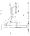
- Fig. 1B is a diagrammatic view of the system of Figs. 7-8 showing the docking of a test head in a projected cradle with the electrical interface of a handler;
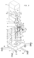
- Fig. 2 is a perspective view of a test head positioner system in accordance with the present invention;
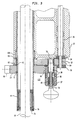
- Fig. 3 is a perspective cutaway view of a portion of Fig. 1;
- Fig. 4 is a perspective cutaway view of an alternate embodiment of the present invention;
- Fig. 5 is a perspective view of the detailed structure of the positioner assembly;
- Fig. 6 diagrammatically shows the six degrees of freedom of the system of Figs. 1 through 4;
- Fig. 7 is a perspective view of the projected cradle assembly in accordance with the present invention;
- Fig. 8 is another embodiment of the present invention in which a plurality of shafts, oriented horizontally, and an offset cradle assembly is used;
- Fig. 9 is another embodiment of the present invention in which a cable pivot housing is used;
- Fig. 10 is another embodiment of the present invention in which horizontal linear motion guides are used;
- Figs. 11A-B show further embodiments of the invention with respect to securing the positioner system inside or alongside the test system; and
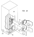
- Fig. 12 shows a further embodiment of the invention with respect to securing the positioner system in a test system cabinet.
-
- The present invention is a
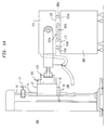
positioner system 150 for positioning anelectronic test head 151 with respect to anelectronic device handler 165. The positioner system allows theelectronic test head 151 to be moved away from the electronic device handler 165 (for adjustments or repairs) while partially maintaining alignment between theelectronic test head 151 and theelectronic device handler 165. By maintaining partial alignment, redocking of theelectronic test head 151 with theelectronic device handler 165 is simplified. - An exemplary embodiment of the positioner system is shown in Figs. 1A and 2. The
positioner system 150 includes ashaft 10 defining a first vertical axis. - A
positioner assembly 100 moves thetest head 151 along the first vertical axis. This is accomplished by movement ofmain arm tube 11 alongshaft 10.Main arm tube 11 can be prevented from moving alongshaft 10 by tightening verticallock screw assembly 14. - The
test head 151 may be moved about the first vertical axis by rotatingupper arm unit 27.Upper arm unit 27 is carried byshoulder lock plate 32 which in turn is carried byindex lock plate 33.Index lock plate 33 is secured totube 11. Thus,index lock plate 33,shoulder lock plate 32 andupper arm unit 27 move withtube 11 along the first vertical axis.Upper arm unit 27 may pivot about the first vertical axis whileshoulder lock plate 32 is maintained stationary. Movement ofupper arm unit 27 relative to shoulderlock plate 32 about the first vertical axis can be prevented by actuatingvernier lock screw 36.Upper arm unit 27 andshoulder lock plate 32 may pivot together about the first vertical axis. Movement ofshoulder lock plate 32 about the first vertical axis is prevented by engaginglock pin 38 in one of several openings inshoulder lock plate 32. - The
test head 151 may be moved about the second vertical axis. The second vertical axis is defined byshaft 40.Forearm 26 moves about the second vertical axis by pivoting aboutshaft 40. Movement offorearm 26 about the second vertical axis can be prevented by actuatinglock screw assembly 104. - The
test head 151 may be moved about the third vertical axis. The third vertical axis is defined by shaft 140.Wrist housing 29 moves about the third vertical axis by pivoting about shaft 140. Movement ofwrist housing 29 about the third vertical axis can be prevented by actuatinglock screw assembly 114. - The
test head 151 may be moved about a horizontal axis. This is accomplished by pivotinghorizontal wrist shaft 30 relative towrist housing 29. Movement ofhorizontal wrist shaft 30 about the horizontal axis can be prevented bylock screw assembly 124. - The various locks within positioner assembly 100 (e.g. 104, 114) are always left unlocked when the
test head 151 is docked with the device handler. This allows thepositioner assembly 100 to float and absorb any motion or vibration from the handler. If the positioner were locked, then the electrical interface betweentest head 151 anddevice handler 165 would absorb the motion or vibration. This may damage the electrical interface. Conversely, the positioner locks are tightened when the test head is undocked. If the positioner locks were not tightened, the test head may move (float), causing possible damage to the equipment and injury to the operator. - The
test head 151 may be undocked and redocked with the device handler with minimal realignment. When the test head is docked with a device handler in the horizontal plane, the test head can be undocked by movingpositioner assembly 100 away from the docked position alongmain shaft 10. After movingpositioner assembly 100, lockscrew assembly 14 can be actuated to ensure that the test head does not move in its undocked state. Thus, damage to the test head and injury to the operator is prevented. The test head can then be pivoted about the first vertical axis to facilitate access to the device handler. This is accomplished by pullinglock pin 38 downward.Lock pin 38 normally engages one of several holes inshoulder lock plate 32. By pullinglock pin 38 downward, shoulder lock plate 32 (and thus upper arm assembly 27) can pivot about the first vertical axis. Thus, although the test head is moved away from the device handler, partial alignment of the test head relative to the device handler is maintained provided all other lock screws (36, 104, 114, 124, etc.) are actuated before thetest head 151 is undocked. To redock the test head with the device handler, shoulder lock plate 32 (and thus upper arm assembly 27) is pivoted back to its original position so thatlock pin 38 again engages the hole inshoulder lock plate 32 whichlock pin 38 originally engaged. Thepositioner assembly 100 is then moved downshaft 10 to the docked position. - When the test head is docked with a device handler in the vertical plane, the test head can be undocked by actuating
lock screw assembly 14 and pivoting the test head about the three vertical axes. By pivoting about the three vertical axes withlock screw assembly 14 actuated, the test head can be manually pushed away from the device handler without changing the positioner assembly's vertical position. Thus, when realigning the test head with the device handler, it is unnecessary to adjust the vertical position of the positioner assembly. After adjustments have been made to the device handler, the positioner assembly can be redocked with the device handler. - Referring now to Fig. 1A, there is shown a test
head positioner system 150 in accordance with the invention. As shown,positioner system 150 carries atest head 151 for a test system for docking withelectrical contactor 167b of anintegrated circuit handler 165. It will be understood that other electronic devices may be handled by the device handler, such as transistors, chips or dies, etc. In operation,positioner assembly 100 is moved manually in a substantially weightless condition to manipulate theheavy test head 151 accurately and precisely and dock it tohandler 165. Docking is accomplished through the use of adocking assembly 170, attached to testhead 151 and adocking gusset assembly 171, attached to thedevice handler 165. In docking,location pins assembly 170 are inserted into correspondingopenings docking gusset assembly 171 andelectrical interface board 167a enters and mates with matingelectrical contactor 167b which electrically connects the test head to the device to be tested.Electrical interface board 167a andelectrical contactor 167b are collectively referred to as the electrical interface. As will later be described in detail, the position oftest head 151 may be accurately manipulated in a substantially weightless condition to another position with six degrees of freedom to dockdocking assembly 170 with other docking gusset assemblies in any position. For example, probers or handlers may be anywhere from a horizontal plane to a vertical plane. Furthermore, it is possible to undock thetest head 151 from theelectrical contactor 167b and to redock thetest head 151 withelectrical contactor 167b with a minimal amount of manipulation of the testhead positioner assembly 100. - The details of
positioner system 150 are shown in Fig. 2 in which there is provided a C-shaped beam forming a vertical housing or support column 45. Column 45 has opposing walls 45a, b, front wall 45c, top plate 45d andbottom plate 45e. Column 45 is supported at its bottom by abase assembly 103 having abase plate 108 and outwardly extendinglegs 109a through 109e which are bolted to the bottom ofplate 108, for example.Wheel assemblies 115a through d are also bolted to the bottom ofplate 108. Column 45 is secured to plate 108 bybolts 108a, for example. The rear of column 45 is enclosed by aU-shaped cover 46 which engages a plurality of pins located onbottom plate 45e.Cover 46 is held in place by a frictional hold relative to walls 45a,b. -
Test head 151, Fig. 1A, is supported and manipulated in its docking bypositioner assembly 100 which is adapted to move vertically on amain shaft 10.Assembly 100 comprisesmain arm tube 11,index lock plate 33,shoulder lock plate 32,upper arm assembly 27,forearm assembly 26,wrist housing assembly 29, andshaft assembly 30.Main shaft 10 is secured in place on the front section of column 45 by opposing pillow blocks 20, 21. -
Positioner assembly 100 is adapted to ride vertically onmain shaft 10 by acounter weight assembly 125 which moves vertically in either direction within the rear section of column 45.Assembly 125 includesweight rod mount 24 with vertically extendingweight rods 2a,b secured thereto andweight 25a coupled to the weight rods. Additional weights (not shown) are added to exactly counterbalance the weight ofassembly 100, together with the test head, so that the test head andassembly 100 are substantially weightless. -
Mount 24 securely receivesflexible cables 105a,b respectively.Cables 105a,b are received through an opening intop plate 45e and are received within grooves of pulleys 23a,b respectively ofpulley assembly 122.Assembly 122 includespulley mount 22 which is secured totop plate 45e. Pulley mount 22 includes an opening through which shoulder screws 96a and 96b are placed. Shoulder screws 96a and 96b permit the rotation of pulleys 23a,b.Pulley assembly 122 is enclosed withinhood 47. -
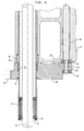
Positioner assembly 100 includesmain arm tube 11 which is disposed aboutmain shaft 10.Main arm tube 11 moves vertically in either direction alongmain shaft 10. The upper end ofmain arm tube 11 is secured to liftblock 19 which in turn is connected to lockcollar 12.Lock collar 12 is also located aboutmain shaft 10. By tighteninglock screw assembly 14, the vertical position ofmain arm tube 11 relative tomain shaft 10 remains fixed. In an exemplary embodiment of the present invention,lock collar 12 may be implemented in accordance with that disclosed in in U. S. Patent No. 4,715,574, incorporated herein by reference. Liftblock 19 securely receivesflexible cables 105a, b, respectively, through a plurality of openings inlock collar 12. In this manner,positioner assembly 100 is coupled tocounter-weight assembly 125. - Referring now to Fig. 3, there is shown the details of a portion of
positioner assembly 100.Retainer ring 77 is a circular member which is secured aboutmain arm tube 11.Retainer ring 77 carriesindex lock plate 33 which slidably engages and supportsshoulder lock plate 32. Alternately,retainer ring 77 may be deleted andindex lock plate 33 attached directly to main arm tube by welding, for example.Index lock plate 33 andshoulder lock plate 32 each include an opening through whichmain arm tube 11 is placed.Upper arm assembly 27 includes a cylindrical member which pivots abouttube 11.Shoulder lock plate 32 supportsupper arm assembly 27 asupper arm assembly 27 pivots about thetube 11. -
Retainer ring 77 is secured tomain arm tube 11 by engagingmain arm tube 11 in one of a plurality of incrementally spaced grooves located onmain arm tube 11. Thus, by insertingretainer ring 77 in a different groove within themain arm tube 11, the height of thepositioner assembly 100 relative tomain arm tube 11 can be adjusted. -
Sleeve bearing 43 is inserted insideshoulder lock plate 32 and aroundmain arm tube 11, thus facilitating rotation ofshoulder lock plate 32 aboutmain arm tube 11.Thrust bearing 82 is located betweenshoulder lock plate 32 andindex lock plate 33.Thrust bearing 82b is located betweenupper arm assembly 27 andmain arm tube 11. Needle bearing 83 is located betweenupper arm assembly 27 and lockshoulder plate 32. Additional bearings are located between moving parts at appropriate places withinsystem 150. Cam followers 80a,b are fastened to indexlock plate 33 and ride on either side ofvertical guide bar 180.Vertical guide bar 180 is attached to column 45, thus preventing the rotation ofindex lock plate 33 aboutmain arm tube 11. - Index
lock pin assembly 132 enablesshoulder lock plate 32 to be locked into one of a plurality of positions aboutmain arm tube 11. Indexlock pin assembly 132 includes indexlock pin housing 37 which is secured to the underside ofindex lock plate 33 byfastener 60. Indexlock pin assembly 132 also includesindex lock pin 38.Index lock pin 38 includes a first portion, with tapered end, which fully occupies an opening inindex plate 33, a second portion, with diameter smaller than the first portion, surrounded by a spring, and a third portion which engages football knob 90, exterior to indexlock pin housing 37.Lock pin 38 is urged towards the opening inshoulder lock plate 33 by spring 95. In an exemplary embodiment,index lock pin 38 may be actuated by using pneumatics or electromagnets, allowingindex lock pin 38 to be moved upward and/or downward from a remote location. Other locks (14, 36, 104, 114, 124, etc.) may also be so remotely controlled. - A plurality of openings are located in
shoulder lock plate 32. These openings are incrementally spaced and can each be lined up withlock pin 38.Lock pin 38 can be urged into any of the openings inshoulder lock plate 32 depending on the orientation ofshoulder lock plate 32 aboutmain arm tube 11. In this manner, the orientation ofshoulder lock plate 32 aboutmain arm tube 11 may be maintained by preventing the pivoting ofshoulder lock plate 32 relative to indexlock plate 33. -
Upper arm assembly 27 includes an opening through whichvernier lock screw 36 is inserted.Vernier lock screw 36 is a stepped shank with threaded end. Football knob 36a (shown in Fig. 4) is secured to non-threaded end oflock screw 36 and is used for rotatingvernier lock screw 36. The threaded end ofvernier lock screw 36 is inserted through a continuous opening which is located along part of the perimeter ofshoulder lock plate 32.Lock pad 34 is located betweenupper arm 27 and lockshoulder plate 32. The shoulder ofvernier lock screw 36 bears against the upper surface oflock pad 34.Lock pad 35 is located belowlock shoulder pad 32. The opening inshoulder pad 35 is threaded to accommodatevernier lock screw 36. By rotatingvernier lock screw 36,lock pad 35 is drawn upwards by the threaded portion ofvernier lock screw 36 andlock pad 34 is pushed downwards by the shoulder ofvernier lock screw 36. Thus, the rotation ofupper arm assembly 27 relative to lockshoulder plate 32 is prevented by tighteningvernier lock screw 36. - In an exemplary embodiment of the present invention,
shoulder lock plate 32 andindex lock plate 33 are replaced with asingle support member 136. This is shown with reference to Fig. 4.Support member 136 is secured tomain arm tube 11.Upper arm assembly 27 slides over the upper surface ofsupport member 136 assupport member 136 remains stationary and supportsupper arm assembly 27 andupper arm assembly 27 pivots abouttube 11.Vernier lock screw 36 allows or prevents rotation ofupper arm assembly 27 relative to lockplate 136 by releasably locking theupper arm assembly 27 to support member. This is described above with reference to Fig. 3. - Referring now to Fig. 5, there is shown the details of a further portion of
positioner assembly 100. - Secured to the front of
upper arm assembly 27 are a pair of mount blocks 28, 29 andlock collar 39 positioned abovemount block 28. -
Forearm 26 rotates with respect toupper arm assembly 27 by way of vertical shafts 40a and b (not shown) which extends through a vertical opening inlock collar 39 throughmount block 28, intoforearm 26 and then from the bottom offorearm 26 into an opening inmount block 29. Vertical shafts 40a and b are rigidly secured withinforearm 26.Forearm 26 may be temporarily prevented from rotation by means oflock screw assembly 104 which is formed withinlock collar 39. -
Forearm 26 has a front "C" shaped section which rotatively receiveswrist housing 29.Lock collar 139 is slidably secured to the upper surface offorearm 26.Wrist housing 29 rotates with respect toforearm 26 by way of vertical shafts 140a and b (not shown). Vertical shaft 140a extends through a vertical opening inlock collar 139, through a vertical opening inforearm 26 and intowrist housing 29. Vertical shaft 140b extends through the bottom ofwrist housing 29 into a lower opening inforearm 26. Shafts 140a and b are rigidly secured withinwrist housing 29.Wrist housing 29 may be temporarily prevented from rotation by means oflock screw assembly 114 which is formed withinlock collar 139. -
Wrist housing 29 includes amember 129 which projects from an end ofwrist housing 29 at a substantially right angle.Horizontal wrist shaft 30 includeshorizontal member 130.Horizontal member 130 is rotatable with respect tomember 129 by means ofhorizontal wrist shaft 30 which extends throughhousing 29.Horizontal member 130 slidably engagesmember 129 to form a disc style lock mechanism.Horizontal member 130 may be temporarily prevented from rotation by tighteninglock screw assembly 144, thus applying pressure betweenhorizontal member 130 andmember 129. -
Cradle assembly 180 is attached toshaft 30 viahorizontal member 130. The test head is attached to thecradle assembly 180 as shown in in U. S. Patent No. 4,705,447 herein incorporated by reference. In this manner,test head 151 may pivot about a plurality of pivot points withincradle assembly 180. When the test head pivots in this manner, the test head is said to undergo test head tumble action. Furthermore, when the test head pivots in this manner, the test head is said to be in tumble mode. The test head docks and undocks with the device handler using the docking apparatus, as described in in U. S. Patent No. 4,705,447. - It will now be understood that
positioner assembly 100 simultaneously positions in 6 degrees of freedom, X, Y, Z, x, y, z. As shown in Fig. 6, it is important for proper docking that testhead 151 have 6 degrees of freedom so thatelectrical contactor 167b can accurately and effortless be positioned with respect toelectrical interface board 167a, for example. - If the Y direction were considered to be the vertical or up/down direction, then the movement of
assembly 100 vertically with respect toshaft 10 provides the Y direction of freedom. - Y freedom, which is the rotation about the Y axis is then provided by rotation of
upper arm 27 abouttube 11,forearm 26 aboutshaft 40 andwrist housing 29 about shaft 140. In addition, a true translated Y rotation with respect to the center of the connectors is provided by the rotation ofupper arm 27 abouttube 11,forearm 26 aboutshaft 40 andwrist housing 29 about shaft 140. - If the X direction were considered to be the left to right direction, then that freedom is provided by pivoting about
main arm tube 11,shaft 40 and shaft 140 in the same manner as Y. - X movement, which is the rotation about the X axis, is provided by pivoting the test head about the pivot points within
cradle assembly 180. - With respect to Z movement which may be considered to be the in and out movement, such freedom is provided by pivoting about
main arm tube 11,shaft 40 and shaft 140 in the same way as Y and X. - Z movement, which is the rotation about the Z axis, is provided by pivoting
shaft 30 relative towrist housing 29. - Test
head positioner system 150 is able to movetest head 151 with 6 degrees of freedom between a docked and an undocked position. Thus,positioner assembly 100 can move vertically alongshaft 10, and pivotal movement is allowed aboutmain arm tube 11,shaft 40, shaft 140 andhorizontal wrist shaft 30. - When
test head 151 is docked withdevice handler 165, all of the locks in test head positioner system 150 (e.g. lockscrew assemblies head positioner system 150 to absorb vibration which is transmitted fromdevice handler 165 to testhead 151. By contrast, whentest head 151 is docked withdevice handler 165, if all the locks in testhead positioner system 150 were locked,electrical interface components 167a,b would absorb transmitted vibrations. This may damage the electrical interface. - When
test head 151 is not docked withdevice handler 165, all of the locks in testhead positioner system 150 may be actuated. This maintains the position oftest head 151. By contrast, whentest head 151 is not docked withdevice handler 165, if the locks in testhead positioner system 150 are unlocked, the heavy test can easily move. This increases the risk of operator injury and equipment damage. - After the
test head 151 has been docked with thedevice handler 165, it may be necessary to undock thetest head 151, make adjustments to thetest head 151 or thedevice handler 165, and then to redock thetest head 151 with thedevice handler 165. The present invention allows this procedure to be accomplished with minimal adjustments to the positioner assembly. - If the
test head 151 has been docked with thedevice handler 165 in the horizontal plane (i.e., the front surface of thetest head 151 is parallel with the floor), then, thetest head 151 is undocked from thedevice handler 165 by actuatinglock screw assemblies test head 151 away from thedevice handler 165 in a vertical direction.Lock screw assembly 14 is then actuated to maintainpositioner assembly 100 in a desired vertical position whiletest head 151 is undocked. Thetest head 151 can then be pivoted about the first vertical axis to facilitate access to thedevice handler 165. This is accomplished by pullinglock pin 38 downward. As previously stated,lock pin 38 normally engages one of several holes inshoulder lock plate 32. By pullinglock pin 38 downward, shoulder lock plate 32 (and thus upper arm assembly 27) can pivot about the first vertical axis, untillock pin 38 is urged into a different hole. Thus, thetest head 151 can be pivoted about the first vertical axis without looseninglock screw assembly 14. When any repairs or adjustments have been completed to the test head or the device handler, redocking of the test head relative to the device handler can be accomplished by pullinglock pin 38 downward, thus allowing shoulder lock plate 32 (and thus upper arm assembly 27) to pivot back to its original position so thatlock pin 38 again engages the hole inshoulder lock plate 32 whichlock pin 38 originally engaged.Lock screw assembly 14 is then loosened and thepositioner assembly 100 is moved to the docked position. - When the test head is docked with a device handler in the vertical plane, the test head can be undocked by actuating
lock screw assembly 14 and pivoting the test head about the three vertical axes. By pivoting about the three vertical axes withlock screw assembly 14 actuated, the test head can be manually pushed away from the device handler without changing the positioner assembly's vertical position. Thus, when realigning the test head with the device handler, it is unnecessary to adjust the vertical position of the positioner assembly. After adjustments have been made to the device handler, the positioner assembly can be redocked with the device handler. - Referring now to Figs. 1B and 7, there is shown still a further embodiment of the present invention. This embodiment includes
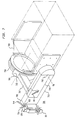
forearm 26 which has a front "C" shaped section which rotatably receiveswrist housing 705.Lock collar 139 is secured to the upper surface offorearm 26.Housing 705 rotates with respect to forearm 701 by way of vertical shafts 704a,b which extend through a vertical opening inlock collar 139, through a vertical opening inforearm 26, intowrist housing 705 and then from the bottom ofwrist housing 705 into a lower opening inforearm 26. Shafts 704a,b are rigidly secured withinwrist housing 705.Wrist housing 705 may be temporarily prevented from rotation by actuatinglock screw assembly 114 which is formed withinlock collar 139. - Projected
cradle assembly 720 includes outer cradle back 713 which is secured towrist housing 705. Outer cradle back 713 is hollow with inner cradle back 714 located therein.Cradle pivot shaft 710 extends through one side of outer cradle back 713, through inner cradle back 714 and through the other side of outer cradle back 713, thus allowing inner cradle back 714 to pivot aboutcradle pivot shaft 710.Cradle side 707 is secured to inner cradle back 714 at substantially right angles through an opening in outer cradle back 713. The opening in outer cradle back 713 allowscradle side 707 to move up or down a minor distance as inner cradle back 714 pivots aboutcradle pivot shaft 710. By actuatinglock screw assembly 711, which extends through an opening in outer cradle back 713 to inner cradle back 714, movement ofcradle side 707 is prevented. - Moving from
wrist housing 705 to cradlepivot shaft 710, the distance between the top and bottom of outer cradle back 713 decreases. Moving fromcradle pivot shaft 710 tocradle side 707, the distance between the top and bottom of inner cradle back 714 decreases. In a preferred embodiment of the present invention, inner cradle back 714 pivots aboutcradle pivot shaft 710 with + / - four degrees of motion. -
Cradle side 707 is attached tocable pivot housing 715, on its opposite end, thereby connecting inner cradle back 714 tocable pivot housing 715.Cable pivot housing 715 retains testhead adapter ring 708 allowingring 708 to rotate (in the X direction) withincable pivot housing 715. The operation ofcable pivot housing 715 and testhead adapter ring 708 is more fully described in U.S. patent application 07/588,144 filed July 15, 1990 herein incorporated by reference. Test head yoke 709a and b is attached to testhead adapter ring 708 and to the test head. In this exemplary embodiment Z movement is provided by the rotation of the inner cradle back 714 aboutcradle pivot shaft 710. - The X movement is provided as previously stated by the rotation of the
test head 151 andyoke 709 via testhead adapter ring 707 rotation withincable pivot housing 715. - It will now be understood that
positioner assembly 100 with this exemplary embodiment simultaneously positions and projects large test heads with 6 degrees of freedom over or under physically large handlers and probers. Thus, the test head may be accurately and effortlessly positioned with respect to the device to be tested as the test head and its cable assembly are rotated at their center of gravity. - Referring now to Fig. 6, there is shown a further embodiment of the present invention in which
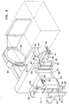
forearm 26 and forearm mounts 28 and 29 are replaced withhorizontal guide assembly 800.Horizontal guide assembly 800 includeslinear guide block 810.Linear guide block 810 is fixedly attached to or integral withupper arm 827. -
Linear guide block 810 has linear bearings for receivinghorizontal shafts Bumper 813 is secured to one end ofshafts shafts horizontal guide block 810. The other end ofhorizontal shafts forearm 826. Horizontal shafts 811,812 may be temporarily prevented from linear motion by actuatinglock screw assembly 804 which is formed withinlinear guide block 810. -
Forearm 826,wrist housing 829 andhorizontal wrist shaft 830 cooperate as described above with respect to the analogous components of Fig. 5. -
Horizontal wrist shaft 830 is attached to cradle back 850. - Cradle back 850 is fixedly attached to
cradle side 890 throughspacer 891. Testhead adapter ring 884 rotates withincable pivot housing 883 as described above with respect to the analogous components of Fig. 7.Yoke 853 is fixedly attached to testhead adapter 884 and to the test head as described above with respect to Fig. 7. - Referring now to Fig. 9, there is shown a further embodiment of the present invention in which
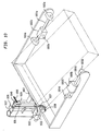
linear guide block 903 is attached toupper arm 927.Linear guide block 903 has linear bearings for receivinghorizontal shafts Bumper 904 is secured to one end ofhorizontal shafts horizontal shafts horizontal guide block 903.Cable pivot adapter 990 is affixed tohorizontal shafts Cable pivot adapter 990 includesflange 981 andbeam 982.Beam 982 is attached to flange 981 on one end and tocable pivot housing 983 on its opposite end, thereby connectingflange 981 andcable pivot housing 983.Cable pivot housing 983 retains testhead adapter ring 984, allowingring 984 to rotate (in the x direction) withinhousing 983. The operation ofcable pivot housing 983 and testhead adapter ring 984 is more fully described in in U. S. Patent Application 07/588,144, filed July 25, 1990 herein incorporated by reference.Test cradle 995 is attached to ring 984. The test head is attached to the cradle through horizontal linear motion guides 940, 950. The details ofguides guide 940 are not shown. - Horizontal linear motion guides 940, 950 include horizontal shafts 901a, 901b which are secured to cradle assembly 995 by mounting blocks 903a, 904a and 903b, 904b, respectively. Linear guide block 902a slides along horizontal shaft 901a. Similarly, linear guide block 902b slides along horizontal shaft 901b. Linear guide blocks 902a, 902b, each include pivot points 905a, 905b secured thereto, which allows the test head to pivot slightly about an axis perpendicular to the axis defined by horizontal shafts 901a, 901b.
- Referring now to Fig. 10, there is shown a further embodiment of the present invention. In this embodiment,
forearm 26 has been deleted. Horizontal wrist housing 1026 is coupled toarm 1027 by way of shafts 1040 a,b inserted through mount blocks 28,29, respectively, with shafts 1040 a,b also inserted throughhorizontal wrist housing 1029. In place offorearm 26 cradle assembly 1006 is coupled towrist housing 1029 by horizontal wrist shaft 1030. Horizontal wrist shaft 1030 allows cradle assembly 1006 to be pivoted about the horizontal axis. By tightening horizontal wrist shaft lock screw (not shown), cradle assembly 1006 can be prevented from rotating about the horizontal axis. - Cradle assembly 1006 includes
horizontal shafts blocks Linear guide block 1002a slides alonghorizontal shaft 1001a. Similarly,linear guide block 1002b slides alonghorizontal shaft 1001b.Linear guide blocks pivot points horizontal shafts shafts 1001 a,b) motion identical to that obtained by allowing rotation about three vertical axes (Figure 2) is obtained. - Referring to Fig. 11A, there is shown
bottom plate 45e which is directly bolted on to the floor immediately next to testcabinet 1111c of the test system. For purposes of simplicity, the elements within column 45 have not been shown. In still another embodiment as shown in Fig. 11B,bottom plate 45e has connected to its lower surface,perpendicular legs test cabinet 1111c. Aleveling pad 1174 may be provided for the leveling of the base. Instead of being bolted tocabinet 1111c, bars 1170, 1171 may be extended (not shown) and coupled to two additional bars holding the remaining two sides of the cabinet. Thus, the four bars may be bolted to each other to rigidly engagecabinet 1111c. - In still another embodiment of the present invention as shown in Fig. 12, the
base 45e has been attached inside thetest system cabinet 1201. By controlling the plurality of locks (e.g. 14,36,104,114,124) by remote control in conjunction with the embodiment of Fig. 7, the test head can be projected by a long outer cradle back 713 to any desired distance. In this manner the complete column mechanism can be enclosed in the test system cabinet and all salient functions of the positioner system can be retained. - While the invention has been described in terms of an exemplary embodiment, it is contemplated that it may be practiced as outlined above with modifications within the spirit and scope of the appended claims.
Claims (15)
- A system for positioning an electronic test head for docking and undocking with an electronic device handler comprising:a support column having a main shaft;a tube disposed about the main shaft and movable along the main shaft;tube locking means for releasably preventing movement of the tube along the shaft;an upper arm assembly having a member for pivoting about the tube;stationary support means secured to the tube and having a surface for supporting the upper arm assembly and over which the upper arm assembly slides as it pivots about the tube; andthe upper arm assembly having upper arm locking means for releasably locking the upper arm assembly to the support means to prevent pivoting of the upper arm unit about the tube.
- A system for positioning an electronic test head for docking and undocking with an electronic device handler comprising:a support column having a main shaft;a tube disposed about the main shaft and movable along the main shaft;tube locking means for preventing movement of the tube along the main shaft;an upper arm assembly having a cylindrical member for pivoting about the tube;shoulder means pivotable about the tube and for slidably engaging and supporting the upper arm assembly as the upper arm assembly pivots about the tube;upper arm locking means for releasably locking the upper arm assembly to the shoulder means to prevent pivoting of the upper arm assembly relative to the shoulder means;lower support means secured to the tube and precluded from rotation for slidably engaging and supporting the shoulder means as it pivots about the tube; andshoulder locking means for releasably locking the shoulder means to the lower support means to prevent pivoting of the shoulder means relative to the lower support means.
- The system of claim 1, further comprising:a retainer ring for supporting said stationary support means; andmeans for securing said retainer ring to said main shaft at one of a plurality of locations along said main shaft.
- The system of claim 1, wherein said upper arm assembly and stationary support means each include an opening, and wherein said upper arm locking means comprises:a locking member having a first end and a second threaded end, said locking member positioned in said upper arm assembly opening and said stationary support means opening, said locking member extending from above said upper arm assembly to below said stationary support means;a lock pad having a threaded opening and located below said stationary support means;said second locking member end extending into and engaging said lock pad threaded opening;said locking member including a shoulder located above said shoulder means;
wherein rotation of said locking member causes said lock pad and said shoulder to be drawn towards said stationary support means, thereby causing friction against said shoulder means and preventing movement of said upper arm assembly relative to said shoulder means. - The system of claim 2, further comprising:a retainer ring for supporting said lower support means; andmeans for securing said retainer ring to said main shaft at one of a plurality of locations along said main shaft.
- The system of claim 2, wherein said upper arm assembly and said shoulder means each include an opening, and wherein said upper arm locking means comprises:a locking member having a first end and a second threaded end, said locking member positioned in said upper arm assembly opening and said shoulder means opening, said locking member extending from above said upper arm assembly to below said shoulder means;a lock pad having a threaded opening and located below said shoulder means,said second locking member end extending into and engaging said lock pad threaded opening;said locking member including a shoulder located above said shoulder means;
wherein rotation of said locking member causes said lock pad and said shoulder to be drawn towards said shoulder means, thereby causing friction against said shoulder means and preventing movement of said upper arm assembly relative to said shoulder means. - The system of claim 2, wherein said shoulder means includes a plurality of openings and said lower support means includes an opening, said shoulder locking means comprising:a shaft;means for inserting and maintaining said shaft into one of said plurality of openings in said shoulder means.
- The system of claim 7, wherein said shaft is maintained in said opening in said lower support means.
- A system for positioning an electronic test head for docking and undocking with an electronic device handler in accordance with claims 1 or 2, said system including a projected cradle assembly coupled to said upper arm assembly for providing rotation of said electronic test head about a center of gravity, said projected cradle assembly comprising:an outer cradle back having an opening, a first end and a second end;an inner cradle back having a first end and a second end, said inner cradle back extending through said opening and coupled to said outer cradle back;said inner cradle back pivotable about an axis located near the second end of said outer cradle back and the second end of said inner cradle back; andmeans for coupling said test head to said inner cradle back for pivotable movement of said test head about said center of gravity.
- A system for positioning an electronic test head according to claims 1 or 2, wherein said main shaft defines a first vertical axis and said upper arm assembly defines a second vertical axis spaced from said first vertical axis, said system further comprising:(a) a forearm:having means for mounting said forearm to said upper arm assembly for pivotal movement about said second vertical axis; defining a third vertical axis;(b) a wrist housing:having means for mounting said wrist housing to said forearm for pivotal movement about said third vertical axis; defining a horizontal axis;(c) a horizontal wrist shaft:having means for mounting said horizontal wrist shaft to said wrist housing for pivotal movement about said horizontal axis;having means for coupling said test head to said horizontal wrist shaft.
- A system for positioning an electronic test head according to claims 1 or 2, wherein said main shaft defines a first vertical axis and said upper arm assembly defines a second vertical axis spaced from said first vertical axis, said system further comprising:(a) a forearmhaving means for mounting said forearm to said upper arm assembly for pivotal movement about said second vertical axis; defining a horizontal forearm axis;(b) a cradle assemblyhaving means for mounting said cradle assembly to said forearm for pivotal movement about said horizontal forearm axis;having horizontal linear motion guide means for providing horizontal movement of the electronic test head along a first horizontal axis with respect to the main shaft.
- A system for positioning an electronic test head according to claims 1 or 2, said system further comprising:(a) first horizontal linear motion guide means, coupled to said upper arm assembly, for providing horizontal movement of the electronic test head along a second horizontal axis with respect to the main shaft;(b) a cradle assembly, coupled to said first horizontal linear motion guide means, and having second horizontal linear motion guide means for providing horizontal movement of the electronic test head along a third horizontal axis with respect to the first horizontal linear motion guide means.
- A system for positioning an electronic test head according to claim 10, further comprising:wherein at least one of said tube locking means, said upper arm locking means, said first locking means, said second locking means and said third locking means are unlocked when said electronic test head is docked with said electronic device handler.(a) first locking means for releasably preventing pivotal movement of said forearm about said second vertical axis when said first locking means is locked;(b) second locking means for releasably preventing pivotal movement of said wrist housing about said third vertical axis when said second locking means is locked;(c) third locking means for releasably preventing pivotal movement of said horizontal wrist shaft about said horizontal axis when said third locking means is locked;
wherein at least one of said tube locking means, said upper arm locking means, said first locking means, said second locking means and said third locking means are locked when said electronic test head is undocked with said electronic device handler; and - A system for positioning an electronic test head according to claim 11, further comprising:(a) first locking means for releasably preventing pivotal movement of said forearm about said second vertical axis when said first locking means is locked;(b) second locking means for releasably preventing pivotable movement of said cradle assembly about said horizontal forearm axis when said first locking means is locked;(c) third locking means for releasably preventing horizontal movement of said electronic test head along said horizontal axis when said third locking means is locked;
wherein at least one of said tube locking means, said upper arm locking means, said first locking means, said second locking means, and said third locking means are locked when said electronic test head is undocked with said electronic device handler; and wherein at least one of said tube locking means, said upper arm locking means, said first locking means, said second locking means and said third locking means are unlocked when said electronic test head is docked with said electronic device handler. - A system for positioning an electronic test head according to claim 12, further comprising:(a) first locking means for releasably preventing horizontal movement of said electronic test head along said second horizontal axis when said first locking means is locked;(b) second locking means for releasably preventing horizontal movement of said electronic test head along said third horizontal axis when said second locking means is locked;
wherein at least one of said tube locking means, said upper arm locking means, said first locking means and said second locking means are locked when said electronic test head is undocked with said electronic device handler; and
wherein at least one of said tube locking means, said upper arm locking means, said first locking means, and said second locking means are unlocked when said electronic test head is docked with said electronic device handler.
Applications Claiming Priority (3)
| Application Number | Priority Date | Filing Date | Title |
|---|---|---|---|
| US07/734,192 US5241870A (en) | 1991-07-22 | 1991-07-22 | Test head manipulator |
| US734192 | 1991-07-22 | ||
| EP92306504A EP0526996B1 (en) | 1991-07-22 | 1992-07-15 | Test head manipulator |
Related Parent Applications (1)
| Application Number | Title | Priority Date | Filing Date |
|---|---|---|---|
| EP92306504A Division EP0526996B1 (en) | 1991-07-22 | 1992-07-15 | Test head manipulator |
Publications (3)
| Publication Number | Publication Date |
|---|---|
| EP0916955A2 true EP0916955A2 (en) | 1999-05-19 |
| EP0916955A3 EP0916955A3 (en) | 1999-09-15 |
| EP0916955B1 EP0916955B1 (en) | 2003-10-29 |
Family
ID=24950681
Family Applications (2)
| Application Number | Title | Priority Date | Filing Date |
|---|---|---|---|
| EP99101970A Expired - Lifetime EP0916955B1 (en) | 1991-07-22 | 1992-07-15 | Test head manipulator |
| EP92306504A Expired - Lifetime EP0526996B1 (en) | 1991-07-22 | 1992-07-15 | Test head manipulator |
Family Applications After (1)
| Application Number | Title | Priority Date | Filing Date |
|---|---|---|---|
| EP92306504A Expired - Lifetime EP0526996B1 (en) | 1991-07-22 | 1992-07-15 | Test head manipulator |
Country Status (7)
| Country | Link |
|---|---|
| US (2) | US5241870A (en) |
| EP (2) | EP0916955B1 (en) |
| JP (1) | JP3391473B2 (en) |
| KR (1) | KR100240476B1 (en) |
| DE (2) | DE69233241T2 (en) |
| MY (2) | MY114024A (en) |
| SG (2) | SG70050A1 (en) |
Families Citing this family (57)
| Publication number | Priority date | Publication date | Assignee | Title |
|---|---|---|---|---|
| US5440943A (en) * | 1993-09-15 | 1995-08-15 | Intest Corporation | Electronic test head manipulator |
| US5600258A (en) * | 1993-09-15 | 1997-02-04 | Intest Corporation | Method and apparatus for automated docking of a test head to a device handler |
| WO1996006714A1 (en) * | 1994-08-30 | 1996-03-07 | Hydrostress Ag | Stand for a stone-working machine, especially a core boring machine |
| US5982182A (en) * | 1994-09-01 | 1999-11-09 | Chiu; Michael A. | Interface apparatus for automatic test equipment with positioning modules incorporating kinematic surfaces |
| US5818219A (en) * | 1994-11-24 | 1998-10-06 | Advantest Corp. | Semiconductor test system having test head connection apparatus |
| JP3869465B2 (en) * | 1995-02-23 | 2007-01-17 | テラダイン・インコーポレーテッド | Manipulator for test head of automatic test equipment |
| US5912555A (en) * | 1995-04-10 | 1999-06-15 | Tokyo Electron Limited | Probe apparatus |
| US5608334A (en) * | 1995-04-20 | 1997-03-04 | Intest Corporation | Device testing system with cable pivot and method of installation |
| US5606262A (en) * | 1995-06-07 | 1997-02-25 | Teradyne, Inc. | Manipulator for automatic test equipment test head |
| US5656942A (en) * | 1995-07-21 | 1997-08-12 | Electroglas, Inc. | Prober and tester with contact interface for integrated circuits-containing wafer held docked in a vertical plane |
| US5756908A (en) * | 1996-07-15 | 1998-05-26 | Framatome Technologies, Inc. | Probe positioner |
| DE19718398B4 (en) * | 1997-04-30 | 2006-02-02 | Heigl, Helmuth, Dr.-Ing. | handling device |
| US6023173A (en) * | 1997-04-30 | 2000-02-08 | Credence Systems Corporation | Manipulator with expanded range of motion |
| US5821440A (en) * | 1997-04-30 | 1998-10-13 | Credence Systems Corporation | Cable tray assembly for testing device |
| US6006616A (en) * | 1997-07-11 | 1999-12-28 | Credence Systems Corporation | Semiconductor tester with power assist for vertical test head movement |
| US5949002A (en) * | 1997-11-12 | 1999-09-07 | Teradyne, Inc. | Manipulator for automatic test equipment with active compliance |
| US6000290A (en) * | 1997-11-12 | 1999-12-14 | Rosemount Analytical Inc. | Quick-connect industrial process sensor |
| US6271658B1 (en) | 1998-10-19 | 2001-08-07 | St Assembly Test Services Pte, Ltd. | Universal Docking System |
| US6888343B1 (en) * | 1999-01-13 | 2005-05-03 | Intest Ip Corporation | Test head manipulator |
| US6310486B1 (en) | 1999-10-01 | 2001-10-30 | Teradyne, Inc. | Integrated test cell |
| MY144519A (en) * | 2000-03-01 | 2011-09-30 | Intest Corp | Vertical counter balanced test head manipulator |
| US6396257B1 (en) * | 2000-04-26 | 2002-05-28 | Credence Systems Corporation | Test head manipulator for semiconductor tester with manual assist for vertical test head movement |
| US6408500B1 (en) * | 2000-09-15 | 2002-06-25 | James Orsillo | Method of retrofitting a probe station |
| WO2002024400A2 (en) * | 2000-09-20 | 2002-03-28 | Intest Ip Corp. | Electronic test head positioner |
| US6766996B1 (en) | 2001-07-16 | 2004-07-27 | Reid-Ashman Manufacturing, Inc. | Manipulator |
| DE60238767D1 (en) * | 2001-07-16 | 2011-02-10 | Intest Corp | SYSTEM AND METHOD FOR COUPLING A TEST HEAD |
| KR100583949B1 (en) * | 2002-01-07 | 2006-05-26 | 삼성전자주식회사 | Wafer probing apparatus and its docking control methods for test head |
| US6646431B1 (en) | 2002-01-22 | 2003-11-11 | Elite E/M, Inc. | Test head manipulator |
| EP1495336A2 (en) | 2002-04-15 | 2005-01-12 | Intest IP Corporation | Test head positioner system |
| US6717432B2 (en) * | 2002-04-16 | 2004-04-06 | Teradyne, Inc. | Single axis manipulator with controlled compliance |
| US6867578B1 (en) * | 2002-09-03 | 2005-03-15 | Credence Systems Corporation | Semiconductor integrated circuit tester with pivoting interface unit |
| ITTO20020783A1 (en) * | 2002-09-06 | 2004-03-07 | Spea Spa | POSITIONING DEVICE FOR AN ELECTRONIC HEAD |
| DE20214629U1 (en) * | 2002-09-20 | 2002-11-21 | Esmo Ag | Sliding mounting plate |
| US20040197180A1 (en) * | 2003-02-04 | 2004-10-07 | Sausen Earl William | Fall protected test-head manipulator |
| EP1947466B1 (en) | 2003-08-06 | 2012-07-04 | inTEST Corporation | Test head positioning system |
| JP2005091041A (en) | 2003-09-12 | 2005-04-07 | Advantest Corp | Apparatus for testing semiconductor |
| DE102004008487B4 (en) * | 2004-02-20 | 2007-01-04 | Heigl, Helmuth, Dr. | Handling device for positioning a test head |
| US7042239B1 (en) | 2004-06-25 | 2006-05-09 | Credence Systems Corporation | Arrangement for manual disengagement of a device interface board from a personal tester |
| US7301326B1 (en) * | 2004-07-13 | 2007-11-27 | Intest Corporation | Modular interface |
| US7312604B2 (en) * | 2005-07-29 | 2007-12-25 | Nextest Systems Corporation | Portable manipulator for stackable semiconductor test system |
| US8607935B2 (en) | 2005-12-20 | 2013-12-17 | Intuitive Surgical Operations, Inc. | Guide systems for laminated spring assemblies |
| TWI490513B (en) | 2006-12-29 | 2015-07-01 | Intest Corp | Load positioning system for translating load along axis of translation and method of balancing load |
| EP2104862B1 (en) * | 2006-12-29 | 2012-08-08 | inTEST Corporation | Test head positioning system and method |
| US7758295B2 (en) * | 2007-05-09 | 2010-07-20 | Datatronics Technology, Inc. | Handling device and method for the same |
| US7802764B2 (en) * | 2007-05-14 | 2010-09-28 | Leinen Chris M | Adjustable wheeled IV stand |
| US8212578B1 (en) | 2008-03-17 | 2012-07-03 | Intest Corporation | Test head positioner system |
| DE102008044756A1 (en) * | 2008-08-28 | 2010-03-04 | Esmo Ag | manipulator |
| KR100939224B1 (en) | 2009-04-07 | 2010-02-01 | 주식회사 일성에프에이 | Jig for testing high temperature of electronic components |
| CN101870102B (en) * | 2009-04-25 | 2013-12-11 | 鸿富锦精密工业(深圳)有限公司 | Palletizing robot |
| US9682484B2 (en) * | 2009-07-24 | 2017-06-20 | GM Global Technology Operations LLC | Counterbalance mechanism for end-effector configuration and method of use |
| US8981807B2 (en) | 2010-07-27 | 2015-03-17 | Intest Corporation | Positioner system and method of positioning |
| WO2013009817A1 (en) | 2011-07-12 | 2013-01-17 | Intest Corporation | Method and apparatus for docking a test head with a peripheral |
| TWI553763B (en) * | 2014-01-23 | 2016-10-11 | 先進科技新加坡有限公司 | A test handler that picks up electronic devices for testing and an orientation-changing apparatus for use in a test handler |
| CN104034922B (en) * | 2014-06-10 | 2017-02-01 | 同济大学 | Bench test holding device for hub motor and rim motor |
| US10978262B2 (en) * | 2017-10-20 | 2021-04-13 | Otis Elevator Company | Reach tool for use in low voltage applications |
| CN108453788B (en) * | 2018-04-20 | 2020-07-10 | 华中科技大学 | Reversible mechanical arm gravity moment balancing device |
| US10933525B2 (en) * | 2018-07-04 | 2021-03-02 | Fanuc Corporation | Horizontal articulated robot |
Citations (4)
| Publication number | Priority date | Publication date | Assignee | Title |
|---|---|---|---|---|
| US1638086A (en) * | 1925-02-07 | 1927-08-09 | Ray L Carter | Adjustable support for routing machines |
| US3040434A (en) * | 1958-01-31 | 1962-06-26 | Roman S Yarosz | Rotatable work table |
| US4705447A (en) * | 1983-08-11 | 1987-11-10 | Intest Corporation | Electronic test head positioner for test systems |
| EP0308348A1 (en) * | 1987-09-17 | 1989-03-22 | Schlumberger Industries | Test head robot for automatic testing |
Family Cites Families (22)
| Publication number | Priority date | Publication date | Assignee | Title |
|---|---|---|---|---|
| US1386025A (en) * | 1920-09-01 | 1921-08-02 | Reinhart W Pittman | Tripod for cameras |
| US3128887A (en) * | 1960-02-25 | 1964-04-14 | Mechanical manipulators for the displacement of | |
| US3262593A (en) * | 1963-07-10 | 1966-07-26 | Gen Mills Inc | Wall-mounted support structure |
| US3269681A (en) * | 1965-01-27 | 1966-08-30 | Wakeem R Azim | Adjustable support apparatus |
| US3727873A (en) * | 1971-07-19 | 1973-04-17 | J Hill | Adjustable crane seat |
| US3884365A (en) * | 1974-03-19 | 1975-05-20 | Thomson Ind Inc | Workpiece manipulator |
| US4062455A (en) * | 1976-11-22 | 1977-12-13 | Flatau Carl R | Remote manipulator |
| US4132318A (en) * | 1976-12-30 | 1979-01-02 | International Business Machines Corporation | Asymmetric six-degree-of-freedom force-transducer system for a computer-controlled manipulator system |
| EP0001686B1 (en) * | 1977-10-20 | 1981-11-04 | Imperial Chemical Industries Plc | An industrial manipulator for placing articles in close proximity to adjacent articles and a method of close packing articles therewith |
| JPS571116Y2 (en) * | 1978-01-31 | 1982-01-08 | ||
| JPS5548598A (en) * | 1978-09-29 | 1980-04-07 | Fujitsu Fanuc Ltd | Load reducing device of industrial robot |
| DE2852821B1 (en) * | 1978-12-07 | 1980-04-30 | Walter Reis Maschinenbau, 8753 Obernburg | manipulator |
| FR2461556A1 (en) * | 1979-07-18 | 1981-02-06 | Bretagne Atel Chantiers | REMOTE HANDLING ARM |
| DE7921541U1 (en) * | 1979-07-27 | 1979-10-31 | Ernst Leitz Wetzlar Gmbh, 6330 Wetzlar | INSTRUMENT BASE FOR OPTICAL DEVICES |
| US4345847A (en) * | 1979-12-19 | 1982-08-24 | Technicare Corporation | Automatic brake sequencing for overhead support arm assemblies |
| GB2074337B (en) * | 1980-04-15 | 1983-11-16 | Univ Technology | Adjustable support for an optical or other instrument |
| US4588346A (en) * | 1982-08-25 | 1986-05-13 | Intest Corporation | Positioner for maintaining an object in a substantially weightless condition |
| US4527942A (en) * | 1982-08-25 | 1985-07-09 | Intest Corporation | Electronic test head positioner for test systems |
| US4866998A (en) * | 1985-09-20 | 1989-09-19 | Temple University Of The Commonwealth System Of Higher Education | Medical examination table with probe holder |
| US4744552A (en) * | 1986-05-20 | 1988-05-17 | Glendo Corporation | Craftsman's jewelry support tool |
| DE3813477C1 (en) * | 1988-04-21 | 1989-11-23 | Ekkehard 8201 Raubling De Ueberreiter | Apparatus for holding an object |
| JP2881865B2 (en) * | 1989-11-24 | 1999-04-12 | 日本電気株式会社 | Flying probe head |
-
1991
- 1991-07-22 US US07/734,192 patent/US5241870A/en not_active Expired - Lifetime
-
1992
- 1992-07-15 SG SG1997004327A patent/SG70050A1/en unknown
- 1992-07-15 SG SG1996000935A patent/SG45172A1/en unknown
- 1992-07-15 DE DE69233241T patent/DE69233241T2/en not_active Expired - Fee Related
- 1992-07-15 EP EP99101970A patent/EP0916955B1/en not_active Expired - Lifetime
- 1992-07-15 EP EP92306504A patent/EP0526996B1/en not_active Expired - Lifetime
- 1992-07-15 DE DE69229985T patent/DE69229985T2/en not_active Expired - Fee Related
- 1992-07-21 MY MYPI96003453A patent/MY114024A/en unknown
- 1992-07-21 MY MYPI92001290A patent/MY125577A/en unknown
- 1992-07-22 KR KR1019920013068A patent/KR100240476B1/en not_active IP Right Cessation
- 1992-07-22 JP JP19514292A patent/JP3391473B2/en not_active Expired - Fee Related
-
1994
- 1994-08-29 US US08/297,326 patent/US5450766A/en not_active Expired - Lifetime
Patent Citations (4)
| Publication number | Priority date | Publication date | Assignee | Title |
|---|---|---|---|---|
| US1638086A (en) * | 1925-02-07 | 1927-08-09 | Ray L Carter | Adjustable support for routing machines |
| US3040434A (en) * | 1958-01-31 | 1962-06-26 | Roman S Yarosz | Rotatable work table |
| US4705447A (en) * | 1983-08-11 | 1987-11-10 | Intest Corporation | Electronic test head positioner for test systems |
| EP0308348A1 (en) * | 1987-09-17 | 1989-03-22 | Schlumberger Industries | Test head robot for automatic testing |
Non-Patent Citations (1)
| Title |
|---|
| ANONYMOUS: "Probe Holder. February 1970." IBM TECHNICAL DISCLOSURE BULLETIN, vol. 12, no. 9, February 1970, pages 1373-1374, XP002106990 New York, US * |
Also Published As
| Publication number | Publication date |
|---|---|
| KR100240476B1 (en) | 2000-01-15 |
| DE69233241T2 (en) | 2004-05-27 |
| EP0526996A2 (en) | 1993-02-10 |
| JPH06226681A (en) | 1994-08-16 |
| EP0526996B1 (en) | 1999-09-15 |
| SG70050A1 (en) | 2000-01-25 |
| MY125577A (en) | 2006-08-30 |
| DE69233241D1 (en) | 2003-12-04 |
| US5241870A (en) | 1993-09-07 |
| US5450766A (en) | 1995-09-19 |
| JP3391473B2 (en) | 2003-03-31 |
| MY114024A (en) | 2002-07-31 |
| EP0916955B1 (en) | 2003-10-29 |
| DE69229985D1 (en) | 1999-10-21 |
| DE69229985T2 (en) | 2000-04-20 |
| SG45172A1 (en) | 1998-01-16 |
| EP0526996A3 (en) | 1993-07-07 |
| EP0916955A3 (en) | 1999-09-15 |
Similar Documents
| Publication | Publication Date | Title |
|---|---|---|
| US5241870A (en) | Test head manipulator | |
| US4589815A (en) | Electronic test head positioner for test systems | |
| US4705447A (en) | Electronic test head positioner for test systems | |
| US4588346A (en) | Positioner for maintaining an object in a substantially weightless condition | |
| EP0643308B1 (en) | Electronic test head manipulator | |
| US5149029A (en) | Electronic test head positioner for test systems | |
| US5606262A (en) | Manipulator for automatic test equipment test head | |
| US8035406B2 (en) | Test head positioning system and method | |
| US7276894B2 (en) | Dynamic cradle assembly positioner system for positioning an electronic device test head | |
| EP0102217B1 (en) | Electronic test head positioner for test systems | |
| EP0979415B1 (en) | Manipulator with expanded range of motion | |
| US5608334A (en) | Device testing system with cable pivot and method of installation | |
| EP0237698B1 (en) | Electronic test head positioner for test systems | |
| EP1601980B1 (en) | Wrist joint for positioning a test head | |
| EP0237697B1 (en) | Electronic test head positioner for test systems | |
| US6717432B2 (en) | Single axis manipulator with controlled compliance |
Legal Events
| Date | Code | Title | Description |
|---|---|---|---|
| PUAI | Public reference made under article 153(3) epc to a published international application that has entered the european phase |
Free format text: ORIGINAL CODE: 0009012 |
|
| AC | Divisional application: reference to earlier application |
Ref document number: 526996 Country of ref document: EP |
|
| AK | Designated contracting states |
Kind code of ref document: A2 Designated state(s): DE FR GB IT NL |
|
| PUAL | Search report despatched |
Free format text: ORIGINAL CODE: 0009013 |
|
| RIN1 | Information on inventor provided before grant (corrected) |
Inventor name: HOLT, ALYN R., INTEST CORPORATION |
|
| AK | Designated contracting states |
Kind code of ref document: A3 Designated state(s): DE FR GB IT NL |
|
| RIC1 | Information provided on ipc code assigned before grant |
Free format text: 6G 01R 1/04 A, 6G 01R 1/067 B, 6B 23Q 1/14 B, 6B 25J 9/10 B, 6G 12B 5/00 B, 6B 23Q 1/16 B |
|
| 17P | Request for examination filed |
Effective date: 20000315 |
|
| 17Q | First examination report despatched |
Effective date: 20020304 |
|
| RAP1 | Party data changed (applicant data changed or rights of an application transferred) |
Owner name: INTEST IP CORP. |
|
| GRAH | Despatch of communication of intention to grant a patent |
Free format text: ORIGINAL CODE: EPIDOS IGRA |
|
| GRAS | Grant fee paid |
Free format text: ORIGINAL CODE: EPIDOSNIGR3 |
|
| GRAA | (expected) grant |
Free format text: ORIGINAL CODE: 0009210 |
|
| AC | Divisional application: reference to earlier application |
Ref document number: 0526996 Country of ref document: EP Kind code of ref document: P |
|
| AK | Designated contracting states |
Kind code of ref document: B1 Designated state(s): DE FR GB IT NL |
|
| REG | Reference to a national code |
Ref country code: GB Ref legal event code: FG4D |
|
| RIC1 | Information provided on ipc code assigned before grant |
Ipc: 7B 25J 9/10 B Ipc: 7B 23Q 1/48 B Ipc: 7G 01R 1/067 B Ipc: 7G 01R 1/04 A |
|
| REF | Corresponds to: |
Ref document number: 69233241 Country of ref document: DE Date of ref document: 20031204 Kind code of ref document: P |
|
| PG25 | Lapsed in a contracting state [announced via postgrant information from national office to epo] |
Ref country code: GB Free format text: LAPSE BECAUSE OF NON-PAYMENT OF DUE FEES Effective date: 20040715 |
|
| PGFP | Annual fee paid to national office [announced via postgrant information from national office to epo] |
Ref country code: NL Payment date: 20040727 Year of fee payment: 13 |
|
| ET | Fr: translation filed | ||
| PLBE | No opposition filed within time limit |
Free format text: ORIGINAL CODE: 0009261 |
|
| STAA | Information on the status of an ep patent application or granted ep patent |
Free format text: STATUS: NO OPPOSITION FILED WITHIN TIME LIMIT |
|
| 26N | No opposition filed |
Effective date: 20040730 |
|
| PG25 | Lapsed in a contracting state [announced via postgrant information from national office to epo] |
Ref country code: DE Free format text: LAPSE BECAUSE OF NON-PAYMENT OF DUE FEES Effective date: 20050201 |
|
| GBPC | Gb: european patent ceased through non-payment of renewal fee |
Effective date: 20040715 |
|
| PG25 | Lapsed in a contracting state [announced via postgrant information from national office to epo] |
Ref country code: FR Free format text: LAPSE BECAUSE OF NON-PAYMENT OF DUE FEES Effective date: 20050331 |
|
| REG | Reference to a national code |
Ref country code: FR Ref legal event code: ST |
|
| PG25 | Lapsed in a contracting state [announced via postgrant information from national office to epo] |
Ref country code: IT Free format text: LAPSE BECAUSE OF NON-PAYMENT OF DUE FEES;WARNING: LAPSES OF ITALIAN PATENTS WITH EFFECTIVE DATE BEFORE 2007 MAY HAVE OCCURRED AT ANY TIME BEFORE 2007. THE CORRECT EFFECTIVE DATE MAY BE DIFFERENT FROM THE ONE RECORDED. Effective date: 20050715 |
|
| PG25 | Lapsed in a contracting state [announced via postgrant information from national office to epo] |
Ref country code: NL Free format text: LAPSE BECAUSE OF NON-PAYMENT OF DUE FEES Effective date: 20060201 |
|
| REG | Reference to a national code |
Ref country code: HK Ref legal event code: WD Ref document number: 1019931 Country of ref document: HK |
|
| NLV4 | Nl: lapsed or anulled due to non-payment of the annual fee |
Effective date: 20060201 |