EP0916941A2 - Method and apparatus for detecting a functional condition of an NOx occlusion catalyst - Google Patents
Method and apparatus for detecting a functional condition of an NOx occlusion catalyst Download PDFInfo
- Publication number
- EP0916941A2 EP0916941A2 EP98119402A EP98119402A EP0916941A2 EP 0916941 A2 EP0916941 A2 EP 0916941A2 EP 98119402 A EP98119402 A EP 98119402A EP 98119402 A EP98119402 A EP 98119402A EP 0916941 A2 EP0916941 A2 EP 0916941A2
- Authority
- EP
- European Patent Office
- Prior art keywords
- oxygen
- nox
- pumping
- concentration
- detecting
- Prior art date
- Legal status (The legal status is an assumption and is not a legal conclusion. Google has not performed a legal analysis and makes no representation as to the accuracy of the status listed.)
- Granted
Links
Images


Classifications
-
- F—MECHANICAL ENGINEERING; LIGHTING; HEATING; WEAPONS; BLASTING
- F01—MACHINES OR ENGINES IN GENERAL; ENGINE PLANTS IN GENERAL; STEAM ENGINES
- F01N—GAS-FLOW SILENCERS OR EXHAUST APPARATUS FOR MACHINES OR ENGINES IN GENERAL; GAS-FLOW SILENCERS OR EXHAUST APPARATUS FOR INTERNAL COMBUSTION ENGINES
- F01N3/00—Exhaust or silencing apparatus having means for purifying, rendering innocuous, or otherwise treating exhaust
- F01N3/08—Exhaust or silencing apparatus having means for purifying, rendering innocuous, or otherwise treating exhaust for rendering innocuous
- F01N3/0807—Exhaust or silencing apparatus having means for purifying, rendering innocuous, or otherwise treating exhaust for rendering innocuous by using absorbents or adsorbents
- F01N3/0828—Exhaust or silencing apparatus having means for purifying, rendering innocuous, or otherwise treating exhaust for rendering innocuous by using absorbents or adsorbents characterised by the absorbed or adsorbed substances
- F01N3/0842—Nitrogen oxides
-
- B—PERFORMING OPERATIONS; TRANSPORTING
- B01—PHYSICAL OR CHEMICAL PROCESSES OR APPARATUS IN GENERAL
- B01D—SEPARATION
- B01D53/00—Separation of gases or vapours; Recovering vapours of volatile solvents from gases; Chemical or biological purification of waste gases, e.g. engine exhaust gases, smoke, fumes, flue gases, aerosols
- B01D53/34—Chemical or biological purification of waste gases
- B01D53/92—Chemical or biological purification of waste gases of engine exhaust gases
- B01D53/94—Chemical or biological purification of waste gases of engine exhaust gases by catalytic processes
- B01D53/9495—Controlling the catalytic process
-
- F—MECHANICAL ENGINEERING; LIGHTING; HEATING; WEAPONS; BLASTING
- F01—MACHINES OR ENGINES IN GENERAL; ENGINE PLANTS IN GENERAL; STEAM ENGINES
- F01N—GAS-FLOW SILENCERS OR EXHAUST APPARATUS FOR MACHINES OR ENGINES IN GENERAL; GAS-FLOW SILENCERS OR EXHAUST APPARATUS FOR INTERNAL COMBUSTION ENGINES
- F01N11/00—Monitoring or diagnostic devices for exhaust-gas treatment apparatus, e.g. for catalytic activity
-
- F—MECHANICAL ENGINEERING; LIGHTING; HEATING; WEAPONS; BLASTING
- F02—COMBUSTION ENGINES; HOT-GAS OR COMBUSTION-PRODUCT ENGINE PLANTS
- F02D—CONTROLLING COMBUSTION ENGINES
- F02D41/00—Electrical control of supply of combustible mixture or its constituents
- F02D41/02—Circuit arrangements for generating control signals
- F02D41/021—Introducing corrections for particular conditions exterior to the engine
- F02D41/0235—Introducing corrections for particular conditions exterior to the engine in relation with the state of the exhaust gas treating apparatus
- F02D41/027—Introducing corrections for particular conditions exterior to the engine in relation with the state of the exhaust gas treating apparatus to purge or regenerate the exhaust gas treating apparatus
- F02D41/0275—Introducing corrections for particular conditions exterior to the engine in relation with the state of the exhaust gas treating apparatus to purge or regenerate the exhaust gas treating apparatus the exhaust gas treating apparatus being a NOx trap or adsorbent
- F02D41/028—Desulfurisation of NOx traps or adsorbent
-
- F—MECHANICAL ENGINEERING; LIGHTING; HEATING; WEAPONS; BLASTING
- F02—COMBUSTION ENGINES; HOT-GAS OR COMBUSTION-PRODUCT ENGINE PLANTS
- F02D—CONTROLLING COMBUSTION ENGINES
- F02D41/00—Electrical control of supply of combustible mixture or its constituents
- F02D41/02—Circuit arrangements for generating control signals
- F02D41/14—Introducing closed-loop corrections
- F02D41/1438—Introducing closed-loop corrections using means for determining characteristics of the combustion gases; Sensors therefor
- F02D41/1444—Introducing closed-loop corrections using means for determining characteristics of the combustion gases; Sensors therefor characterised by the characteristics of the combustion gases
- F02D41/146—Introducing closed-loop corrections using means for determining characteristics of the combustion gases; Sensors therefor characterised by the characteristics of the combustion gases the characteristics being an NOx content or concentration
- F02D41/1463—Introducing closed-loop corrections using means for determining characteristics of the combustion gases; Sensors therefor characterised by the characteristics of the combustion gases the characteristics being an NOx content or concentration of the exhaust gases downstream of exhaust gas treatment apparatus
-
- G—PHYSICS
- G01—MEASURING; TESTING
- G01N—INVESTIGATING OR ANALYSING MATERIALS BY DETERMINING THEIR CHEMICAL OR PHYSICAL PROPERTIES
- G01N27/00—Investigating or analysing materials by the use of electric, electrochemical, or magnetic means
- G01N27/26—Investigating or analysing materials by the use of electric, electrochemical, or magnetic means by investigating electrochemical variables; by using electrolysis or electrophoresis
- G01N27/416—Systems
- G01N27/417—Systems using cells, i.e. more than one cell and probes with solid electrolytes
-
- F—MECHANICAL ENGINEERING; LIGHTING; HEATING; WEAPONS; BLASTING
- F01—MACHINES OR ENGINES IN GENERAL; ENGINE PLANTS IN GENERAL; STEAM ENGINES
- F01N—GAS-FLOW SILENCERS OR EXHAUST APPARATUS FOR MACHINES OR ENGINES IN GENERAL; GAS-FLOW SILENCERS OR EXHAUST APPARATUS FOR INTERNAL COMBUSTION ENGINES
- F01N2550/00—Monitoring or diagnosing the deterioration of exhaust systems
- F01N2550/02—Catalytic activity of catalytic converters
-
- F—MECHANICAL ENGINEERING; LIGHTING; HEATING; WEAPONS; BLASTING
- F01—MACHINES OR ENGINES IN GENERAL; ENGINE PLANTS IN GENERAL; STEAM ENGINES
- F01N—GAS-FLOW SILENCERS OR EXHAUST APPARATUS FOR MACHINES OR ENGINES IN GENERAL; GAS-FLOW SILENCERS OR EXHAUST APPARATUS FOR INTERNAL COMBUSTION ENGINES
- F01N2550/00—Monitoring or diagnosing the deterioration of exhaust systems
- F01N2550/03—Monitoring or diagnosing the deterioration of exhaust systems of sorbing activity of adsorbents or absorbents
-
- F—MECHANICAL ENGINEERING; LIGHTING; HEATING; WEAPONS; BLASTING
- F01—MACHINES OR ENGINES IN GENERAL; ENGINE PLANTS IN GENERAL; STEAM ENGINES
- F01N—GAS-FLOW SILENCERS OR EXHAUST APPARATUS FOR MACHINES OR ENGINES IN GENERAL; GAS-FLOW SILENCERS OR EXHAUST APPARATUS FOR INTERNAL COMBUSTION ENGINES
- F01N2570/00—Exhaust treating apparatus eliminating, absorbing or adsorbing specific elements or compounds
- F01N2570/04—Sulfur or sulfur oxides
-
- Y—GENERAL TAGGING OF NEW TECHNOLOGICAL DEVELOPMENTS; GENERAL TAGGING OF CROSS-SECTIONAL TECHNOLOGIES SPANNING OVER SEVERAL SECTIONS OF THE IPC; TECHNICAL SUBJECTS COVERED BY FORMER USPC CROSS-REFERENCE ART COLLECTIONS [XRACs] AND DIGESTS
- Y02—TECHNOLOGIES OR APPLICATIONS FOR MITIGATION OR ADAPTATION AGAINST CLIMATE CHANGE
- Y02T—CLIMATE CHANGE MITIGATION TECHNOLOGIES RELATED TO TRANSPORTATION
- Y02T10/00—Road transport of goods or passengers
- Y02T10/10—Internal combustion engine [ICE] based vehicles
- Y02T10/40—Engine management systems
Definitions
- the present invention relates to a method and apparatus for detecting a functional condition of an NOx occlusion catalyst.
- NOx-concentration detecting apparatus for detecting the concentration of NOx (NOx) contained in exhaust gases from internal combustion engines and the like using an NOx sensor are disclosed, for example, in European Patent Application Laid-Open No. 0678740A1 and SAE Paper No. 960334, pp. 137-142, 1996.
- An NOx sensor used in such a conventional NOx-concentration detecting apparatus is composed of oxygen-ion conductive solid electrolyte layers that define a first measurement space and a second measurement space.
- the first measurement space communicates with a gas to be measured (hereinafter called "a measurement gas") via a first diffusion-controlling layer
- the second measurement space communicates with the first measurement space via a second diffusion-controlling layer.
- the NOx-concentration detecting apparatus current is applied to the first oxygen-pumping cell such that the output voltage from the oxygen-concentration-measuring cell achieves a predetermined value, thereby controlling the concentration of oxygen contained in the first measurement space at a constant level.
- a constant voltage is applied to the second oxygen-pumping cell to thereby pump out oxygen from the second measurement space.
- the NOx concentration of a measurement gas can be obtained by measuring the current flowing through the second oxygen-pumping cell.
- a measurement gas e.g., exhaust from an internal combustion engine or the like, contains gas components other than NOx, such as oxygen, carbon monoxide and carbon dioxide.
- the first oxygen-pumping cell is activated so as to control the concentration of oxygen contained in the first measurement space to a very low level.
- a constant voltage is applied to the second oxygen-pumping cell in a direction such that oxygen is pumped out from the second measurement space.
- the NOx concentration of the measurement gas can be obtained by measuring the current flowing through the second oxygen-pumping cell with no influence of other gas components contained in the measurement gas.
- Such a refreshing operation is performed periodically at constant intervals or when the amount of leakage of NOx from the NOx occlusion catalyst exceeds a predetermined level.
- the amount of NOx leakage is detected using the NOx-concentration measuring apparatus described above, including the NOx sensor installed in an exhaust passage of the internal combustion engine at a location downstream of the NOx occlusion catalyst.
- the NOx sensor used in such an application must at least be able to determine the NOx concentration in units of 100 ppm.
- Fig. 12 shows the results of measuring the offset of the second pumping current when an apparatus is operated while a test gas not containing NOx is used as a measurement gas (measurement with three different sensors).
- the amount of offset varies depending on the differences between NOx sensors and also on the air-fuel ratio of the measurement gas.
- the offset varies accordingly, by several to tens of ppm.
- the NOx concentration must at least be determined in units of 100 ppm. Thus, a sufficient detection accuracy has not yet been obtained.
- the NOx occlusion catalyst stores the sulfur, in the form of sulfate, on an NOx storage material. Since sulfate is less likely to react with unburned components than is nitrate, sulfate cannot be removed by executing the refreshing operation described above. As a result, the NOx occlusion capability deteriorates to an extent corresponding to the amount of accumulated sulfate.
- a waiting time Tw is provided.
- a second pumping current first detected after the elapse of the waiting time Tw is determined to be a reference value IP2s.
- the second pumping current IP2 detected at time t1 is used as the reference value IP2s in calculating a relative value of a subsequently detected second pumping current IP2, the relative value will not exceed the predetermined value Ic, which serves as a reference value in judging a functional deterioration of the NOx occlusion catalyst. As a result, control may be disabled.
- the present invention generally relates to a method and apparatus for detecting a functional condition of an NOx occlusion catalyst using an NOx sensor adapted to detect the concentration of NOx emitted from various combustion apparatus, including internal combustion engines.
- the present invention seeks to provide a method and apparatus for accurately detecting a functional condition of an NOx occlusion using an NOx sensor.
- the above object has been achieved by providing:
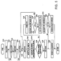
- Fig. 1 is a schematic diagram showing the entire configuration of an apparatus for detecting a functional condition of an NOx occlusion catalyst according to a first embodiment of the present invention.
- Fig. 2 is a diagram showing an installation location for an NOx sensor 2 used in the detection apparatus.
- Fig. 3 is an exploded perspective view of the NOx sensor 2.
- the detection apparatus of the present embodiment includes an NOx sensor 2 mounted in an exhaust pipe S2 attached to an internal combustion engine S1 of a vehicle at a location downstream of an NOx occlusion catalyst S3; a drive circuit 40 for applying current to a first oxygen-pumping cell (hereinafter referred to as a first pumping cell) 4 and an oxygen-concentration-measuring cell (hereinafter referred to as a Vs cell) 6 of the NOx sensor 2 and for detecting current (hereinafter referred to as first pumping current) IP1 which flows to the first pumping cell 4; a sensing circuit 42 for applying a constant voltage to the second pumping cell 8 and for detecting current (hereinafter referred to as second pumping current) IP2 which flows to a second oxygen-pumping cell (hereinafter referred to as a second pumping cell) 8 of the NOx sensor 2; a heater-energizing circuit 44 for heating the cells 4, 6 and 8 by applying current to a pair
- the detection apparatus of the present embodiment receives operation control information indicative of execution of operation control at a lean air-fuel ratio from an engine control unit 52.
- the engine control unit 52 controls the operating conditions of the internal combustion engine S1 such that a lean air-fuel ratio is effected while operating conditions are stable, as in the case of travel at a constant speed, and a theoretical air-fuel ratio is effected in other cases.
- exhaust gas flowing through the exhaust pipe S2 is referred to as follows: gas emitted from the internal combustion engine S1 and flowing into the NOx occlusion catalyst S3 is referred to as exhaust gas, whereas gas flowing out from the NOx occlusion catalyst S3 is referred to as a measurement gas.
- the first pumping cell 4 includes a sheet-like solid electrolyte layer 4a and rectangular porous electrodes 4b and 4c formed on both sides of the solid electrolyte layer 4a. Lead portions 4b1 and 4c1 extend from the porous electrodes 4b and 4c, respectively. Furthermore, a round hole is formed in the solid electrolyte layer 4a so as to penetrate the porous electrodes 4b and 4c at their central portions. The thus-formed round hole is filled with a porous filler to thereby form a diffusion-controlling layer 4d.
- the Vs cell 6 includes a sheet-like solid electrolyte layer 6a having the same shape as the solid electrolyte layer 4a of the first pumping cell 4 and circular porous electrodes 6b and 6c formed on both sides of the solid electrolyte layer 6a. Lead portions 6b1 and 6c1 extend from the porous electrodes 6b and 6c, respectively. Furthermore, a round hole is formed in the solid electrolyte layer 6a so as to penetrate the porous electrodes 6b and 6c at their central portions. The thus-formed round hole is filled with a porous filler to thereby form a diffusion-controlling layer 6d.
- the porous electrodes 4b and 4c of the first pumping cell 4 and the porous electrodes 6b and 6c of the Vs cell 6 are located on the solid electrolyte layers 4a and 6a, respectively, such that their centers are aligned with each other. Accordingly, when the first pumping cell 4 and the Vs cell 6 are arranged in layers, the diffusion-controlling layers 4d and 6d face each other.
- the circular porous electrodes 6b and 6c of the Vs cell 6 are arranged around the diffusion-controlling layer 6d and have a size that is smaller than that of the rectangular porous electrodes 4b and 4c of the first pumping cell 4.
- An insulation film formed of alumina or the like is formed on both surfaces of the Vs cell 6 so as to cover the lead portions 6b1 and 6c1 from the outside in order to prevent current leakage from the lead portions 6b1 and 6c1. Furthermore, a leakage resistance portion 6f is formed between the lead portions 6b1 and 6c1 in order to leak part of pumped-out oxygen from the side of the porous electrode 6c to the side of the porous electrode 6b.
- the first pumping cell 4 and the Vs cell 6 are arranged in layers with a solid electrolyte layer 18 interposed therebetween.
- the solid electrolyte layer 18 has the same shape as that of the solid electrolyte layers 4a and 6a.
- the solid electrolyte layer 18 has a rectangular hole formed therein in a position corresponding to the porous electrodes 4c and 6b and having a size greater than that of the porous electrode 4c. The thus-formed rectangular hole serves as a first measurement space 20.
- a solid electrolyte layer 22 which has the same shape as that of the solid electrolyte layers 4a and 6a, is placed on the Vs cell 6 on the side of the porous electrode 6c.
- the solid electrolyte layer 22 has a round hole formed therein in a position corresponding to the diffusion-controlling layer 6d of the Vs cell 6 and having the same size as that of the diffusion-controlling layer 6d. The thus-formed round hole is filled with a porous filler to thereby form a diffusion-controlling layer 22d.
- the second pumping cell 8 includes a sheet-like solid electrolyte layer 8a and rectangular porous electrodes 8b and 8c formed on both sides of the solid electrolyte layer 8a. Lead portions 8b1 and 8c1 extend from the porous electrodes 8b and 8c, respectively.
- the second pumping cell 8 and the solid electrolyte layer 22 are arranged in layers with a solid electrolyte layer 24 interposed therebetween.
- the solid electrolyte layer 24 is formed in the same manner as the solid electrolyte layer 18. As a result, a rectangular hole formed in the solid electrolyte layer 24 serves as a second measurement space 26.
- the above components of the NOx sensor 2 excluding the heaters 12 and 14 are united in layers and subsequently sintered at a predetermined temperature, yielding the NOx sensor 2.
- the heaters 12 and 14 are placed on opposite sides of the above-described laminate of the first pumping cell 4, the Vs cell 6 and the second pumping cell 8, namely, outside the first pumping cell 4 and the second pumping cell 8, respectively, such that a predetermined gap is formed between each of the heaters 12 and 14 and the laminate using spacers 28 and 29.
- the heater 12 (14) includes a heater substrate 12a (14a) having a shape same as that of the solid electrolyte layers 4a, 6a and 8a, a heater wiring 12b (14b) formed on the heater substrate 12a (14a) on the side facing the cell 4 (8), and a lead portion 12b1 (14b1) extending from the heater wiring 12b (14b).
- the spacer 28 (29) is interposed between the heater 12 (14) and the first pumping cell 4 (second pumping cell 8) at a position corresponding to the lead portion 12b1 so that the heater wiring 12b (14b) faces the porous electrode 4b (8c) of the first pumping cell 4 (second pumping cell 8) with a gap formed therebetween.
- the heater substrate 12a (14a) is formed of alumina.
- the heater wiring is formed by the steps of: blending platinum powder and alumina to obtain a mixture paste; screen-printing a pattern of the paste on an alumina sheet; and firing the sheet.
- the heater substrates 12a and 14a and the spacers 28 and 29 are each formed of fired alumina sheets.
- the heaters 12 and 14 and the first and second pumping cells 4 and 8 are bonded together using a ceramic bonding agent such that the cells 4 and 8 are sandwiched between the heaters 12 and 14, thereby forming the complete NOx sensor 2.
- Typical examples of a solid electrolyte forming the solid electrolyte layers 4a, 6a and 8a include a solid solution of zirconia and yttria and a solid solution of zirconia and calcia.
- Other examples of such a solid electrolyte include a solid solution of hafnia, a solid solution of a perovskite oxide, and a solid solution of a trivalent metal oxide.
- the porous electrodes provided on the surfaces of the solid electrolyte layers 4a, 6a and 8a are preferably formed of platinum or rhodium having a catalytic function or their alloys.
- Known methods of forming such a porous electrode include a thick-film forming method and a thermal spraying method.
- the thick-film forming method includes the steps of: mixing platinum powder and powder of the same material as that of the solid electrolyte layers to obtain a paste; screen-printing the paste onto a solid electrolyte layer; and sintering the solid electrolyte layer.
- the diffusion-controlling layers 4d, 6d and 22d are preferably formed of ceramics having fine through-holes or porous ceramics.
- the heater wirings 12b and 14b of the heaters 12 and 14, respectively, are preferably formed of a composite material of ceramics and platinum or a platinum alloy.
- the lead portions 12b1 and 14b1 are preferably formed of platinum or a platinum alloy in order to reduce electric loss therein by reducing their resistance.
- the heater substrates 12a and 14a and the spacers 28 and 29 may be formed of alumina, spinel, forsterite, steatite, zirconia, or a like material.
- the porous electrode 4c of the first pumping cell 4 and the porous electrode 6b of the Vs cell 6, both of which are located on the side of the first measurement space 20, are grounded via a resistor R1.
- the other porous electrodes 4b and 6c are connected to the drive circuit 40.
- the drive circuit 40 includes a resistor R2 and a differential amplifier AMP.
- a constant voltage VCP is applied to one end of the resistor R2, and the other end of the resistor R2 is connected to the porous electrode 6c of the Vs cell 6.
- the negative input terminal of the differential amplifier AMP is connected to the porous electrode 6c of the Vs cell 6 via a switch SW1.
- a reference voltage VC0 is applied to the positive input terminal of the differential amplifier AMP.
- the output terminal of the differential amplifier AMP is connected to the porous electrode 4b of the first pumping cell 4 via a resister R0.
- the drive circuit 40 operates in the following manner. First, a constant small current iCP is supplied to the Vs cell 6 via the resistor R2 to thereby pump out oxygen from the first measurement space 20 into the porous electrode 6c of the Vs cell 6. Because the porous electrode 6c is blocked by the solid electrolyte layer 22 and communicates with the porous electrode 6b via the leakage resistance portion 6f, the concentration of oxygen in the blocked space of the porous electrode 6c is maintained at a constant level by applying a small current iCP to the Vs cell 6. Thus, the blocked space serves as an internal reference oxygen source.
- the porous electrode 6c of the Vs cell serves as an internal reference oxygen source
- an electromotive force is generated in the Vs cell 6 in accordance with the difference in oxygen concentration between the first measurement space 20 and the internal reference oxygen source.
- a voltage Vs developed on the side of the porous electrode 6c corresponds to the concentration of oxygen in the first measurement space 20.
- the differential amplifier AMP outputs a voltage in accordance with the deviation of the input voltage from the reference voltage VC0 (VC0 - input voltage).
- the output voltage is applied to the porous electrode 4b of the first pumping cell 4 via the resistor R0.
- a first pumping current IP1 flows to the first pumping cell 4.
- a constant electromotive force is generated by the Vs cell 6 (in other words, the concentration of oxygen in the first measurement space 20 becomes constant).
- the drive circuit 40 serves as the pumping-current control means, and controls the concentration of oxygen contained in the first measurement space 20 so as to maintain constant the concentration of oxygen in the measurement gas which has entered into the first measurement space 20 via the diffusion-controlling layer 4d.
- the thus-controlled concentration of oxygen in the first measurement space 20 is set such that only a small amount of oxygen (e.g., 1000 ppm) is present, thereby preventing the decomposition of NOx components contained in the measurement gas contained in the first measurement space 20 due to applying the first pumping current IP1 to the first pumping cell 4.
- the reference voltage VC0 for determining this concentration of oxygen is set at 100 mV to 200 mV.
- the resistor R0 disposed between the output terminal of the differential amplifier AMP and the porous electrode 4b is adapted to detect the first pumping current IP1.
- a voltage VIP1 developed across the resistor R0 is input to the ECU 50 as a detection signal corresponding to the first pumping current IP1.
- a constant voltage VP2 is applied between the porous electrodes 8b and 8c of the second pumping cell 8 of the NOx sensor 2 via a resistor R3, which is a component of the sensing circuit 42 and serves as the constant-voltage application source of the invention.
- the constant voltage VP2 is applied to the second pumping cell 8 in a direction such that the porous electrodes 8c and 8b become a positive electrode and a negative electrode, respectively. As a result, current flows from the porous electrode 8c to the porous electrode 8b to thereby pump out oxygen from the second measurement space 26.
- the constant voltage VP2 is set at a voltage, for example 450 mV, such that the NOx component contained in the measurement gas flowing from the first measurement space 20 to the second measurement space 26 via the diffusion-controlling layers 6d and 22d are decomposed, to thereby pump out an oxygen component from the measurement gas.
- the resistor R3 is adapted to convert the second pumping current IP2 flowing through the second pumping cell 8 as a result of applying the constant voltage VP2, to a voltage VIP2, and adapted to input the voltage VIP2 to the ECU 50 as a detection signal corresponding to the second pumping current IP2.
- the control circuit 40 controls the concentration of oxygen in the measurement gas which has entered into the first measurement space 20 via the diffusion-controlling layer (first diffusion-controlling layer) 4d, to a constant level.
- the measurement gas controlled to a constant oxygen concentration flows from the first measurement space 20 to the second measurement space 26 via the diffusion-controlling layers (second diffusion-controlling layers) 6d and 22d.
- the first pumping current IP1 flowing through the first pumping cell 4 varies in accordance with the concentration of oxygen in the measurement gas.
- the second pumping current IP2 flowing through the second pumping cell 8 varies in accordance with the concentration of NOx in the measurement gas.
- the ECU 50 can determine the concentrations of oxygen and NOx in the measurement gas.
- the temperature of the NOx sensor 2 is preferably controlled to a constant level. To meet this requirement, current applied to the heaters 12 and 14 from the heater-energizing circuit 44 is controlled so that the temperature TH detected by the temperature sensor 46 achieves a target temperature.
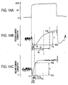
- Figs. 4(a)-(c) and also Figs. 14(a)-(c) show graphs of the measured second pumping current IP2 of the NOx sensor 2, which is located downstream of the NOx occlusion catalyst S3, when the engine control unit 52 switches the operation control mode of the internal combustion engine S1 from operation control at a theoretical air-fuel ratio (hereinafter referred to as normal control) to operation control at a lean air-fuel ratio (hereinafter referred to as lean control).
- normal control a theoretical air-fuel ratio
- lean control lean air-fuel ratio
- Fig. 4(c) and Fig. 14(c) show the resulting measurement in the case of fuel containing sulfur, illustrating deterioration in the NOx occlusion capability caused by accumulation of sulfur on the NOx occlusion catalyst S3 in the form of sulfate.
- the rate of increase or slope in the second pumping current IP2 is greater than in Fig. 4(b) and in Fig. 14(b).
- This process is repeatedly executed after the NOx sensor 2 is activated by applying current to the heaters 12 and 14.
- S110 (S represents "step"), a timer for use in the process is reset. Subsequently, in S120, based on operation control information received from the engine control unit 52, the ECU 50 determines whether the engine control unit 52 has started lean control. Upon detecting the start of lean control, the ECU 50 proceeds to S130.
- the ECU 50 starts the time which was reset in S110. Subsequently, in S140, the ECU 50 determines whether a waiting time Tw has elapsed.
- the concentration of oxygen in the exhaust gas is unstable. Accordingly, the offset of the second pumping current IP2 varies, thereby disabling accurate detection.
- the waiting time Tw is set to a length such that variation in the second pumping current IP2 induced by switching the control mode is sufficiently settled.
- the ECU 50 Upon detecting elapse of the waiting time Tw in S140, the ECU 50 proceeds to S150. In S150, the ECU 50 reads the detection signal VIP2 to thereby detect the second pumping current IP2, namely, the ECU 50 serves as the second pumping-current detection means.
- the ECU 50 detects the temperature TH of the NOx sensor 2, the negative pressure Pb in the suction pipe, and the engine speed Ne using the temperature sensor 46, the pressure sensor 47, and the rotational speed sensor 48, respectively. Subsequently, in S170, the ECU 50 calculates allowable variation ranges for the negative pressure Pb in the suction pipe and the engine speed Ne.
- the allowable variation ranges are determined by the steps of: calculating respective average values of the negative pressure Pb in the suction pipe and the engine speed Ne detected repeatedly in S160; and determining a range composed of each of the calculated average values, serving as a center value of the range, and a predetermined tolerance (for example, ⁇ 10%), as a set value for each of the allowable variation ranges.
- the allowable variation ranges serve as reference values for detecting abrupt variations of the flow rate of exhaust gas flowing into the NOx occlusion catalyst S3, the concentration of NOx in the exhaust gas, and the air-fuel ratio.
- Exhaust gas conditions are not directly detected, but are indirectly detected based on operating conditions of the internal combustion engine S1, such as the engine speed Ne and the negative pressure Pb in the suction pipe which are determinants of the exhaust gas conditions.
- the second pumping current IP2 detected in S150 is compensated for temperature based on the sensor temperature TH, which will be described later.
- sufficiently high accuracy may not be obtained even through compensated for temperature.
- allowable variation ranges are defined in which a sufficiently high accuracy can be obtained by temperature compensation.
- the ECU 50 judges whether the negative pressure Pb in the suction pipe and the engine speed Ne detected in S160 fall within the respective allowable variation ranges set in S170. When even either Pb or Ne fails to fall within the corresponding allowable variation range, the ECU 50 proceeds to S190 and stops the timer. Subsequently, in S200, the ECU 50 outputs a request for refreshment of the NOx occlusion catalyst S3 to the engine control unit 52 and terminates the detection process.
- S180 when the ECU 50 judges that both the negative pressure Pb in the suction pipe and the engine speed Ne fall within the respective allowable variation ranges, the ECU 50 proceeds to S210.
- S210 serving as the second correction means, the ECU 50 corrects the second pumping current IP2 detected in S150 based on the sensor temperature TH detected in S160.
- current applied to the heater-energizing circuit 44 is controlled such that the temperature detected by the temperature sensor 46 becomes constant.
- the NOx sensor 2 is affected by the temperature variation.
- both the first pumping current IP1 and the second pumping current IP2 vary.
- the second pumping current IP2 takes a relatively long time (about 1 minute) until it is stabilized.
- the temperature of the NOx sensor 2 is measured by means of the temperature sensor 46, and the amount of temperature correction is determined based on the measured temperature and using, for example, the temperature correction map of Fig. 6. Based on the thus determined amount of temperature correction, the second pumping current IP2 is corrected.
- the predetermined value Ic is not particularly limited so long as the value Ic is smaller than the second pumping current IP2 as detected when the NOx occlusion catalyst becomes disabled and does not store NOx at all, but is preferably about 70% to 80% of the detected second pumping current IP2.
- the relative value ⁇ IP2 becomes equal to or greater than the predetermined value Ic, resulting in a YES judgment in S230.
- the ECU 50 then proceeds to S240.
- S240 serving as the current-increasing-time measuring means
- the ECU 50 stops the timer and records the reading of the timer as a measurement TO.
- S250 serving as the allowable value setting means
- the ECU 50 calculates a time threshold Tth used for detecting an anomaly in the occlusion capability of the NOx occlusion catalyst S3.
- the time threshold Tth is calculated in the following manner.
- the ECU 50 estimates the flow rate of exhaust gas and the concentration of NOx contained in the exhaust gas based on respective average values of the negative pressure Pb in the suction pipe and the engine speed Ne which are repeatedly detected in S160 while the timer is active. Based on the estimated flow rate and NOx concentration, the ECU 50 estimates the time required for the second pumping current IP2 to exceed the predetermined value Ic. The thus-estimated time is set as the time threshold Tth.
- the time threshold Tth may be determined using a map which contains as parameters an average negative pressure Pb in the suction pipe and an average engine speed Ne.
- the ECU 50 determines whether the measurement TO stored in S240 is smaller than the time threshold Tth. In the case of a NO judgment, the ECU 50 considers that the NOx occlusion catalyst S3 suffers functional deterioration due to accumulation of nitrate, and proceeds to S200. In S200, the ECU 50 outputs a request for refreshing of the NOx occlusion catalyst S3 to the engine control unit 52.
- the ECU 50 considers that the NOx occlusion catalyst S3 suffers an anomaly, such as accumulation of sulfate or exfoliation of an NOx storage material, and proceeds to S270.
- the ECU 50 outputs a request for catalyst burnout to the engine control unit 52 and then terminates the detection process.
- the engine control unit 52 Upon receipt of a request for refreshment from the ECU 50, the engine control unit 52 controls the operating conditions of the internal combustion engine S1 so as to temporarily establish a rich air-fuel ratio, thereby causing unburned gas to be emitted from the internal combustion engine S1. By reaction of the unburned gas with nitrate accumulated on the NOx occlusion catalyst S3, the NOx occlusion catalyst S3 is refreshed.
- the engine control unit 52 Upon receiving a request for catalyst burnout from the ECU 50, the engine control unit 52 temporarily establishes such conditions so as to reduce sulfate accumulated on the NOx occlusion catalyst S3 by reaction, thereby refreshing (burning out) the NOx occlusion catalyst S3.
- the relative value ⁇ IP2 with respect to the second pumping current IP2 detected at the time t1 after start of lean control, or operation control of the internal combustion engine S1 at a lean air-fuel ratio increases by the predetermined value Ic, namely, when the amount of NOx leaking from the NOx occlusion catalyst S3 increases by a predetermined value, the occlusion capability of the NOx occlusion catalyst S3 is judged to have deteriorated.
- a time TO required for the relative value ⁇ IP2 to increase by the predetermined value Ic is smaller than the time threshold Tth, the occlusion capability of the NOx occlusion catalyst S3 is judged to suffer an anomaly.
- an offset of the second pumping current IP2 is compensated for temperature variation.
- detection is not affected by variation of the sensor temperature, if any, during detection.
- parameters (the negative pressure Pb in the suction pipe and the engine speed Ne) indicative of operating conditions of the internal combustion engine S1 are successively detected.
- this phenomenon is considered indicative of abrupt variation in operating conditions.
- judgment on functional deterioration is interrupted, and a request for refreshment is immediately output.
- the present embodiment is partially different from the first embodiment in the functional condition detection process performed by the ECU 50. Thus, only a different portion of the process will be described.
- the concentration of oxygen in the measurement gas is detected using the NOx sensor 2 with no need for employing a new sensor, environmental variation that affects the second pumping current IP2 can be detected more accurately. Accordingly, the second pumping current IP2 can be corrected accurately.
- a request for refreshment is periodically output at constant intervals of time, and-the functional condition detection process is only adapted to output a request for catalyst burnout.
- the ECU 50 judges whether the relative value ⁇ IP2 calculated in S610 is smaller than the current threshold Ith calculated in S620.
- the relative value ⁇ IP2 of the second pumping current is smaller than the current threshold Ith (namely, the slope of the second pumping current IP2 is smaller than the corresponding allowable value)
- the ECU 50 terminates the detection process.
- the ECU 50 terminates the detection process.
- the slope of the second pumping current IP2 after start of operation control at a lean air-fuel ratio is obtained based on the time TO required for the second pumping current IP2 to increase by a predetermined value, as in the case of the first and second embodiments.
- the slope of the second pumping current IP2 may be obtained based on an increase in ⁇ IP2 of the second pumping current as measured during the fixed time (Tc - Tw). This also enables the present embodiment to produce an effect similar to that produced by the first and second embodiments.
- the present invention is not limited to the above-described embodiments, but may be embodied in various other forms.
- the temperature TH of the NOx sensor 2 is obtained using the temperature sensor 46.
- the resistance of the Vs cell 6 may be detected, and the temperature of the NOx sensor 2 may be obtained based on the detected resistance.
- a time threshold is set based on the negative pressure Pb in the suction pipe and the engine speed Ne.
- any parameter may be used so long as it has an effect on the flow rate of exhaust gas and the concentration of NOx in the exhaust gas.
- the oxygen concentration is detected using the NOx sensor 2.
- a separate oxygen sensor may be employed for detecting the oxygen concentration.
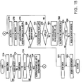
- S710 (S represents "step"), a timer to be used in the process is reset. Subsequently, in S720, the ECU 50 judges whether the engine control unit 52 is performing lean control. Upon detection of lean control being in effect, the ECU 50 proceeds to S730.
- the ECU 50 may judge whether lean control is in effect, on the basis of operation control information received from the engine control unit 52.
- the ECU 50 may detect the first pumping current IP1 by reading the detection signal VIP1 and may judge whether the detected first pumping current IP1 is indicative of an oxygen concentration corresponding to a lean air-fuel ratio, thereby judging whether lean control is in effect.
- the ECU 50 starts the time which was reset in S710. Subsequently, in S740, the ECU 50 reads the detection signal VIP2 to thereby detect the second pumping current IP2, and stores the detected value together with the associated timer value. In S750, the ECU 50 judges whether the waiting time Tw has elapsed. In the case of a NO judgment, the ECU 50 performs S740 again.
- the ECU 50 in S740, repeatedly detects the second pumping current IP2 at intervals of about 5 to 20 ms (sampling rate: 50 Hz to 200 Hz).
- the waiting time Tw is set to a length during which variation in the second pumping current IP2 induced by switching the control mode from normal control to lean control sufficiently settles.
- the ECU 50 proceeds to S760.
- the ECU 50 extracts a minimum value, together with an associated timer value, from among values of the second pumping current IP2 which have been stored through repeated detection in S740 during the waiting time Tw, and stores the extracted minimum value and timer value as a reference second pumping current IP2s and a reference timer value Ts, respectively, (see Figs. 14(b) and 14(c)).
- the last detected minimum value is extracted as the reference second pumping current IP2s.
- a minimum value of the second pumping current IP2 is extracted after elapse of the waiting time Tw.
- the extraction of the minimum value of the second pumping current IP2 may be performed such that during the waiting time Tw, upon each detection of the second pumping current IP2, the detected value is compared with stored values in order to extract the minimum value.
- the ECU 50 reads the detection signal VIP2 to thereby detect the second pumping current IP2
- the S770 step is repeatedly performed, which will be described later. Specifically, in S770, the ECU 50 repeatedly detects the second pumping current IP2 at a detection period longer lower than that in S740, i.e., at intervals of about 20 to 100 ms (sampling rate: 1 Hz to 50 Hz).
- the ECU 50 detects the negative pressure Pb in the suction pipe and the engine speed Ne using of the pressure sensor 47 and the rotational speed sensor 48, respectively. Subsequently, in S790, the ECU 50 calculates allowable variation ranges for the negative pressure Pb in the suction pipe and the engine speed Ne.
- the allowable variation ranges are determined by the steps of: calculating respective average values of the negative pressure Pb in the suction pipe and the engine speed Ne which are repeatedly detected in S780 after the timer is started in S730; and determining a range composed of each of the calculated average values, serving as a center value of the range, and a predetermined tolerance (for example, ⁇ 10%), as a set value for each of the allowable variation ranges.
- the allowable variation ranges serve as reference values for detecting abrupt variations of the flow rate of exhaust gas flowing into the NOx occlusion catalyst S3, the concentration of NOx in the exhaust gas, and air-fuel ratio.
- Exhaust gas conditions are not directly detected, but are indirectly detected based on operating conditions of the internal combustion engine S1, such as the engine peed Ne and the negative pressure Pb in the suction pipe which are determinants of exhaust gas conditions.
- the allowable variation ranges are set so as to reliably obtain a sufficiently high accuracy, thereby preventing an erroneous operation.
- the ECU 50 judges whether the negative pressure Pb in the suction pipe and the engine speed Ne detected in S780 fall within the respective allowable variation ranges set in S790. When even either Pb or Ne fails to fall within the corresponding allowable variation range, the ECU 50 proceeds to S810 and stops the timer. Subsequently, in S820, the ECU 50 outputs a request for refreshment of the NOx occlusion catalyst S3 to the engine control unit 52 and terminates the detection process.
- the ECU 50 judges whether the relative value ⁇ IP2 calculated in S830 is equal to or greater than a predetermined value Ic. In the case of a NO judgment, the ECU 50 considers that the NOx occlusion catalyst S3 still has the occlusion capability (the catalyst S3 is not deteriorated yet), and returns to S770.
- the ECU 50 repeats the steps S770-S800, S830 and S840, the NOx occlusion capability deteriorates, and the concentration of NOx in the measurement gas as measured at a location downstream of the NOx occlusion catalyst S3 increases. Accordingly, the second pumping current IP2 and its relative value ⁇ IP2 increase gradually.
- the relative value ⁇ IP2 becomes equal to or greater than the predetermined value Ic, resulting in a YES judgment in S840.
- the ECU 50 proceeds to S850.
- the ECU 50 calculates a time threshold Tth used for detecting an anomaly in the occlusion capability of the NOx occlusion catalyst S3.
- the time threshold Tth is calculated in the following manner.
- the ECU 50 estimates the flow rate of exhaust gas and the concentration of NOx in the exhaust gas based on respective average values of the negative pressure Pb in the suction pipe and the engine speed Ne which are repeatedly detected in S780 while the timer is active. Based on the estimated flow rate and NOx concentration, the ECU 50 estimates the time required for the second pumping current IP2 to exceed the predetermined value Ic. The thus-estimated time is set as the time threshold Tth.
- the time threshold Tth may be determined using a map which contains as parameters an average negative pressure Pb in the suction pipe and an average engine speed Ne.
- the ECU 50 judges whether the measurement time ⁇ T calculated in S850 is smaller than the time threshold Tth set in S860. In the case of a NO a judgment, the ECU 50 considers that the NOx occlusion catalyst S3 suffers functional deterioration due to accumulation of nitrate, and proceeds to S820. In S820, the ECU 50 outputs a request for refreshing of the NOx occlusion catalyst S3 to the engine control unit 52.
- the ECU 50 considers that the NOx occlusion catalyst S3 suffers an anomaly, such as accumulation of sulfate or exfoliation of an NOx storage material, and proceeds to S880.
- the ECU 50 outputs a request for catalyst burnout to the engine control unit 52 and then terminates the detection process.
- the engine control unit 52 Upon receiving a request for refreshment from the ECU 50, the engine control unit 52 controls operating conditions of the internal combustion engine S1 so as to temporarily establish a rich air-fuel ratio, thereby causing unburned gas to be emitted from the internal combustion engine S1. By reaction of the unburned gas with nitrate accumulated on the NOx occlusion catalyst S3, the NOx occlusion catalyst S3 is refreshed.
- the engine control unit 52 Upon receiving a request for catalyst burnout from the ECU 50, the engine control unit 52 temporarily establishes such conditions as to reduce sulfate accumulated on the NOx occlusion catalyst S3 by reaction, thereby refreshing (burning out) the NOx occlusion catalyst S3.
- the steps S720 to S760 correspond to the minimum value detection means of the present invention
- the steps S830 to S870 correspond to the functional condition judgment means of the present embodiment.
- the apparatus of the present embodiment for detecting a functional condition of the NOx occlusion catalyst does not use an absolute value of the second pumping current IP2, but uses the relative value ⁇ IP2 of the second pumping current, which cancels an offset of the second pumping current IP2, in judging a functional condition of the NOx occlusion catalyst S3 (whether the NOx occlusion catalyst S3 suffers a functional deterioration or a functional anomaly). Thus, accurate judgment can be performed.
- a minimum value of the second pumping current IP2s as detected during the waiting time Tw after start of lean control is used as the reference second pumping current IP2s, which serves as a reference value in calculating the relative value ⁇ IP2 of the second pumping current.
- the detection of the second pumping current IP2 is performed at high speed only during the waiting time Tw.
- the detection of the second pumping current IP2 may be performed at high speed after the elapse of the waiting time Tw if the processing capability allows it.
- a detected value of the second pumping current IP2 is used as such for calculating the relative value ⁇ IP2.
- the second pumping current IP2 may be corrected based on the sensor temperature TH detected by the temperature sensor 46 and the first pumping current IP1 indicative of the concentration of oxygen in the measurement gas, and the thus-corrected second pumping current IP2 may be used for calculating the relative value ⁇ IP2.
- the offset of the second pumping current IP2 varies according to variation in the sensor temperature TH and the concentration of oxygen (air-fuel ratio) in the measurement gas, such an offset variation is compensated for, thereby enabling more accurate detection.
- a minimum value of the second pumping current IP2 as detected during the waiting time Tw is used as the reference second pumping current IP2s.
- an upper limit may be predetermined for a timer value. The case of time-out may be considered as an indication of an anomaly in the occlusion capability of the NOx occlusion catalyst S3, and a request for catalyst burnout may be output.
- a time threshold is set based on the negative pressure Pb in the suction pipe and the engine speed Ne.
- any parameter may be used so long as it has an effect on the flow rate of exhaust gas and the concentration of NOx in the exhaust gas.
Abstract
Description
- The present invention relates to a method and apparatus for detecting a functional condition of an NOx occlusion catalyst.
- NOx-concentration detecting apparatus for detecting the concentration of NOx (NOx) contained in exhaust gases from internal combustion engines and the like using an NOx sensor are disclosed, for example, in European Patent Application Laid-Open No. 0678740A1 and SAE Paper No. 960334, pp. 137-142, 1996. An NOx sensor used in such a conventional NOx-concentration detecting apparatus is composed of oxygen-ion conductive solid electrolyte layers that define a first measurement space and a second measurement space. The first measurement space communicates with a gas to be measured (hereinafter called "a measurement gas") via a first diffusion-controlling layer, and the second measurement space communicates with the first measurement space via a second diffusion-controlling layer. Furthermore, the solid electrolyte layer of the first measurement space is sandwiched between porous electrodes so as to form a first oxygen-pumping cell and an oxygen-concentration-measuring cell. Also, the solid electrolyte layer of the second measurement space is sandwiched between porous electrodes so as to form a second oxygen-pumping cell.
- In the thus-configured NOx-concentration detecting apparatus, current is applied to the first oxygen-pumping cell such that the output voltage from the oxygen-concentration-measuring cell achieves a predetermined value, thereby controlling the concentration of oxygen contained in the first measurement space at a constant level. At the same time, a constant voltage is applied to the second oxygen-pumping cell to thereby pump out oxygen from the second measurement space. At this time, the NOx concentration of a measurement gas can be obtained by measuring the current flowing through the second oxygen-pumping cell.
- A measurement gas, e.g., exhaust from an internal combustion engine or the like, contains gas components other than NOx, such as oxygen, carbon monoxide and carbon dioxide. Thus, in the aforementioned NOx-concentration detecting apparatus, first, the first oxygen-pumping cell is activated so as to control the concentration of oxygen contained in the first measurement space to a very low level. Then, in the second measurement space into which the measurement gas controlled to a low oxygen concentration flows, a constant voltage is applied to the second oxygen-pumping cell in a direction such that oxygen is pumped out from the second measurement space. As a result, NOx contained in the measurement gas is decomposed into nitrogen and oxygen by means of the catalyzing function of the porous electrodes of the second oxygen-pumping cell, and the thus-generated oxygen is then pumped out from the second measurement space. Thus, the NOx concentration of the measurement gas can be obtained by measuring the current flowing through the second oxygen-pumping cell with no influence of other gas components contained in the measurement gas.
- In an NOx-concentration measuring apparatus of this kind, in order to accurately detect the concentration of NOx by the detecting method described above, the sensor must be heated to a predetermined active temperature (for example, 800°C or higher) so as to activate the cells. Therefore, a heater for heating the sensor is additionally provided.
- In recent years, in order to improve fuel consumption and attain high efficiency for internal combustion engines using gasoline as a fuel, internal combustion engines have been developed that are controlled so as to operate at a lean air-fuel ratio, where the amount of air is large with respect to that of the fuel (lean burn engines, direct injection engines, etc.). Normally, in an internal combustion engine, NOx and unburned components (HC and CO) contained in exhaust gas are made to react with each other using a three-way catalytic converter to reduce NOx to N2, thereby purifying the exhaust gas. In operating at a lean air-fuel ratio, a large amount of oxygen is contained in the exhaust gas. As a result, the oxygen reacts with unburned components, resulting in a failure to remove NOx.
- To solve the above problem, a so-called NOx occlusion catalyst is used, which is a three-way catalytic converter containing an NOx storage material for storing NOx contained in exhaust gas in the form of nitrate. However, because of the limited amount of NOx that can be occluded in the NOx occlusion catalyst, the control for refreshing the NOx occlusion catalyst so as to restore its capacity for storing NOx is performed in the following manner. The air-fuel ratio of a mixture fed to an internal combustion engine is temporarily controlled to a rich air-fuel ratio, where the amount of fuel is relatively large, before the amount of stored NOx reaches the above capacity limit. The resulting exhaust gas contains a large amount of unburned components from the internal combustion engine. This causes the unburned components to react with NOx stored in the NOx occlusion catalyst, thereby refreshing the NOx occlusion catalyst so that its capability of storing NOx is restored.
- Such a refreshing operation is performed periodically at constant intervals or when the amount of leakage of NOx from the NOx occlusion catalyst exceeds a predetermined level. In the latter case, the amount of NOx leakage is detected using the NOx-concentration measuring apparatus described above, including the NOx sensor installed in an exhaust passage of the internal combustion engine at a location downstream of the NOx occlusion catalyst.
- In order to perform accurate control, the NOx sensor used in such an application must at least be able to determine the NOx concentration in units of 100 ppm.
- In the NOx sensor, when the oxygen concentration in the first measurement space is controlled to zero by controlling the pumping current, NOx components contained in a measurement gas contained in the first measurement space are decomposed. As a result, the NOx concentration cannot be measured using the second oxygen-pumping cell. Normally, therefore, the oxygen concentration in the first measurement space is controlled such that a small amount of oxygen remains within the first measurement space (for example, a low oxygen concentration of about 1000 ppm). Accordingly, a second pumping current flowing through the second oxygen-pumping cell includes an offset due to the influence of the remaining oxygen. Fig. 11 schematically shows the relationship between the oxygen concentration in a measurement gas and the first pumping-current, as well as the relationship between the NOx concentration and the second pumping-current.
- Fig. 12 shows the results of measuring the offset of the second pumping current when an apparatus is operated while a test gas not containing NOx is used as a measurement gas (measurement with three different sensors).
- The line with circles indicates an NOx sensor No. 1, the line with black diamonds indicates an NOx sensor No. 2, and the line with black triangles indicates an NOx sensor No. 3.
- As shown in Fig. 12, the amount of offset varies depending on the differences between NOx sensors and also on the air-fuel ratio of the measurement gas. When the air-fuel ratio varies with changes in operating conditions or the like, the offset varies accordingly, by several to tens of ppm. However, in order to accurately perform refreshment control for the NOx occlusion catalyst, the NOx concentration must at least be determined in units of 100 ppm. Thus, a sufficient detection accuracy has not yet been obtained.
- Thus, in order to reliably prevent the increase in NOx leakage from the NOx occlusion catalyst beyond a predetermined value, a refreshing operation must be initiated while considerable allowance is given to the NOx occlusion capability of the NOx occlusion catalyst in view of variations in offset. This causes a failure to sufficiently utilize the capability of the NOx occlusion catalyst. This tendency is also observed when the refreshing operation is performed periodically.
- When sulfur (S) is present in exhaust gas, the NOx occlusion catalyst stores the sulfur, in the form of sulfate, on an NOx storage material. Since sulfate is less likely to react with unburned components than is nitrate, sulfate cannot be removed by executing the refreshing operation described above. As a result, the NOx occlusion capability deteriorates to an extent corresponding to the amount of accumulated sulfate.
- When the NOx occlusion capability deteriorates as above, in the case of periodic refreshment, the cleaning capability with respect to NOx deteriorates. On the other hand, whereas in the case of refreshment based on a detected NOx concentration, refreshment is performed frequently, causing a deterioration in fuel consumption and efficiency of the internal combustion engine.
- It is known that, by executing, for example, the above-described refreshment with the NOx occlusion catalyst being held at a higher temperature (hereinafter referred to as catalyst burnout), sulfate can be removed by reacting with unburned components. Thus, conceivably, sulfate can be removed periodically. However, because of a larger burden on the NOx occlusion catalyst as compared with the case of normal refreshment for the removal of nitrate and potential deterioration of the NOx occlusion catalyst, sulfate removal is desirably performed only as needed.
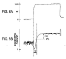
- On the other hand, Fig. 16 shows a second pumping current IP2 measured with the NOx sensor located downstream of the NOx occlusion catalyst when the operation control mode of an internal combustion engine is switched from operation control at a theoretical air-fuel ratio to operation control at a lean air-fuel ratio.
- As shown in Figs. 16(a) and 16(b), immediately after operation control at a theoretical air-fuel ratio is switched to operation control at a lean air-fuel ratio (time t0), the concentration of oxygen contained in exhaust gas varies greatly, and thus the second pumping current varies transiently. In order to wait for variation in the second pumping current to settle, a waiting time Tw is provided. A second pumping current first detected after the elapse of the waiting time Tw is determined to be a reference value IP2s.
- In the case of determining the reference value IP2s as above, the following problem is involved. When the occlusion capability of the NOx occlusion catalyst deteriorates significantly due to, for example, exfoliation of a large amount of an NOx occlusion material, the second pumping current IP2 increases abruptly immediately after the operation control mode is Switched to lean control, as shown in Fig. 16(c). In this case, at time t1 when detection is first carried out after elapse of the waiting time Tw, the second pumping current IP2 has already increased greatly. Thus, if the second pumping current IP2 detected at time t1 is used as the reference value IP2s in calculating a relative value of a subsequently detected second pumping current IP2, the relative value will not exceed the predetermined value Ic, which serves as a reference value in judging a functional deterioration of the NOx occlusion catalyst. As a result, control may be disabled.
- Thus, it is the object of the present invention to overcome the drawbacks and disadvantages of the prior art. This object is solved by the apparatus according to
independent claims 3, 7, 15, 21, 22 and 23 and the method according toindependent claims - Further advantageous features, aspects and details of the invention are evident from the dependent claims, description, examples and figures. The claims are to be understood as a first non-limiting approach of defining the invention in general terms.
- The present invention generally relates to a method and apparatus for detecting a functional condition of an NOx occlusion catalyst using an NOx sensor adapted to detect the concentration of NOx emitted from various combustion apparatus, including internal combustion engines.
- According to one aspect, the present invention seeks to provide a method and apparatus for accurately detecting a functional condition of an NOx occlusion using an NOx sensor.
- In one aspect of the invention, the above object has been achieved by providing:
- (1) A method for detecting a functional condition of an NOx occlusion catalyst, wherein an NOx sensor is disposed in an exhaust pipe of an internal combustion engine at a location downstream of the NOx occlusion catalyst, said NOx sensor comprising a first measurement space having a first oxygen-pumping cell and an oxygen-concentration-measuring cell and communicating with a measurement gas via a first diffusion-controlling layer, each of the first oxygen-pumping cell and the oxygen-concentration-measuring cell comprising an oxygen-ion conductive solid electrolyte layer and porous electrodes disposed on opposite surfaces of the oxygen-ion conductive solid electrolyte layer; a second measurement space having a second oxygen-pumping cell and communicating with the first measurement space via a second diffusion-controlling layer, the second oxygen-pumping cell comprising an oxygen-ion conductive solid electrolyte layer and porous electrodes disposed on opposite surfaces of the oxygen-ion conductive solid electrolyte layer; and a heater for heating the cells to a predetermined active temperature. The method comprises applying a first pumping current to the first oxygen-pumping cell so that an output voltage from the oxygen-concentration-measuring cell achieves a predetermined value, thereby controlling the concentration of oxygen in the first measurement space at a constant level; at the same time, applying a constant voltage to the second oxygen-pumping cell in a direction such that oxygen is pumped out from the second measurement space; detecting a second pumping current which flows through the second oxygen-pumping cell according to the concentration of NOx in the measurement gas; and if an increase of the second pumping current equal to a predetermined value is detected after start of operation control of the internal combustion engine at a lean air-fuel ratio, judging that the occlusion capability of the NOx occlusion catalyst has deteriorated.In the detection method described above, the NOx sensor is operated in a manner similar to that used for measuring NOx concentration. Also, the second pumping current is detected, which flows through the second oxygen-pumping cell according to the concentration of NOx contained in the measurement gas.During operation control at a lean air-fuel ratio, in which exhaust gas containing a large amount of NOx is emitted from an internal combustion engine, NOx contained in the exhaust gas is accumulated in the NOx occlusion catalyst in the form of nitrate. As the thus-accumulated nitrate increases, the occlusion capability of the NOx occlusion catalyst gradually decreases. As a result, leakage of NOx from the NOx occlusion catalyst (namely, the NOx concentration in the measurement gas) increases, resulting in an increase in the second pumping current.As described above, the second pumping current offset is affected by the oxygen concentration in the first measurement space, and the oxygen concentration in the first measurement space, in turn, is affected by the oxygen concentration in the measurement gas, or air-fuel ratio. Accordingly, the offset current depends on the air-fuel ratio. In the detection method of the present invention, the function of the NOx occlusion catalyst is judged by determining whether the second pumping current has increased by a predetermined value after start of operation control at a lean air-fuel ratio, namely, by using a relative value of the second pumping current rather than an absolute value of the second pumping current. If so, then the occlusion capability of the NOx occlusion catalyst is judged to have deteriorated.According to the present invention, so long as during detection the air-fuel ratio of a measurement gas does not vary greatly due to, for example, an abrupt change in operating conditions of an internal combustion engine, the influence of the offset can be reliably removed, thereby allowing for an accurate judgment on the functional condition of the NOx occlusion catalyst. Based on the result of this judgment, a refreshing operation for removing nitrate, for example, can be performed only as needed, thereby improving the fuel consumption and efficiency of an internal combustion engine.In another aspect, the present invention provides: (2) A method for detecting a functional condition of an NOx occlusion catalyst, in which an NOx sensor similar to that described in (1) above is disposed in an exhaust pipe of an internal combustion engine at a location downstream of the NOx occlusion catalyst.The method comprising applying a first pumping current to the first oxygen-pumping cell so that the output voltage from the oxygen-concentration-measuring cell achieves a predetermined value, thereby controlling the concentration of oxygen in the first measurement space at a constant level; at the same time, applying a constant voltage to the second oxygen-pumping cell in a direction such that oxygen is pumped out from the second measurement space; detecting a second pumping current which flows through the second oxygen-pumping cell according to the concentration of NOx contained in the measurement gas; and if a rate of increase of the second pumping current greater than an allowable value is detected after start of operation control of the internal combustion engine at a lean air-fuel ratio, judging that an anomaly has occurred in the occlusion capability of the NOx occlusion catalyst.As described above, as NOx accumulates in the NOx occlusion catalyst, leakage of NOx from the NOx occlusion catalyst increases. Accordingly, the second pumping current flowing through the second oxygen-pumping cell increases. When any anomaly occurs, for example, when sulfate accumulates in the NOx occlusion catalyst or when an NOx storage material exfoliates, the nitrate occlusion capability of the NOx occlusion catalyst deteriorates, resulting in an increase in the rate of leakage of NOx from the NOx occlusion catalyst. As a result, the rate of increase of the second pumping current increases. Thus, by examining the rate of increase of the second pumping current, or the slope of the second pumping current, it is possible to detect anomalies suffered by the NOx occlusion catalyst.Based on the result of this judgment, a refreshing operation for removing sulfate, for example, can be performed only as needed. Because unnecessary burdens are not imposed on the NOx occlusion catalyst, the durability of the apparatus can be improved. Also, for example, when an anomaly is not eliminated even though a refreshing operation for removing sulfate is executed, this indicates the occurrence of an anomaly that cannot be eliminated through refreshment, such as exfoliation of an NOx storage material.In yet another aspect, the present invention provides:
- (3) An apparatus for detecting a functional condition of
an NOx occlusion catalyst, comprising an NOx sensor disposed in
an exhaust pipe of an internal combustion engine at a location
downstream of the NOx occlusion catalyst, the NOx sensor
comprising a first measurement space having a first oxygen-pumping
cell and an oxygen-concentration-measuring cell and
communicating with a measurement gas via a first diffusion-controlling
layer, each of the first oxygen-pumping cell and
the oxygen-concentration-measuring cell comprising an oxygen-ion
conductive solid electrolyte layer and porous electrodes
disposed on opposite surfaces of the oxygen-ion conductive
solid electrolyte layer; a second measurement space having a
second oxygen-pumping cell and communicating with the first
measurement space via a second diffusion-controlling layer, the
second oxygen-pumping cell comprising an oxygen-ion conductive
solid electrolyte layer and porous electrodes disposed on
opposite surfaces of the oxygen-ion conductive solid
electrolyte layer; and a heater for heating the cells to a
predetermined active temperature,
- said apparatus further comprising:
- first pumping-current control means for controlling the concentration of oxygen in said first measurement space at a constant level by applying a first pumping current to the first oxygen-pumping cell such that an output voltage from the oxygen-concentration-measuring cell is maintained at a constant value;
- a constant-voltage application source for applying a constant voltage to the second oxygen-pumping cell in a direction such that oxygen is pumped out from the second measurement space;
- second pumping-current detection means for detecting a second pumping current which flows through said second oxygen-pumping cell according to the concentration of NOx in the measurement gas; and
- functional deterioration judgment means for judging that the occlusion capability of the NOx occlusion catalyst has deteriorated when an increase of the second pumping current equal to a predetermined value is detected after start of operation control of the internal combustion engine at a lean air-fuel ratio. The detection apparatus of the present invention is an apparatus for carrying out the detection method described in (1) above. Specifically, first, the first pumping-current control means causes the first pumping current to flow through the first oxygen-pumping cell such that the output voltage from the oxygen-concentration-measuring cell is maintained at a constant value, thereby controlling the concentration of oxygen in the first measurement space to a constant level. The constant-voltage application means applies a constant voltage to the second oxygen-pumping cell in a direction such that oxygen is pumped out from the second measurement space. The second pumping-current detection means detects the second pumping current flowing through the second oxygen-pumping cell. When the functional deterioration judgment means detects an increase in the second pumping current equal to a predetermined value after start of operation control of the internal combustion engine at a lean air-fuel ratio where the ratio of oxygen to fuel is relatively large, the judgment means judges that the occlusion capability of the NOx occlusion catalyst has deteriorated.Accordingly, the detection apparatus described in (3) above provides a means for carrying out the detection method described in (1). Furthermore, the detection apparatus (3) can simply and accurately detect a functional deterioration of the NOx occlusion catalyst based on a relative value of the second pumping current, thereby improving the fuel consumption and efficiency of an internal combustion engine.Normally, operation control at a lean air-fuel ratio is performed during stable operating conditions, such as during operation at a constant speed. However, when operating conditions vary due to, for example, a driver's operation of an accelerator or variations in road conditions, the concentration of oxygen contained in a measurement gas (air-fuel ratio) varies temporarily. As a result, the offset current of the second oxygen-pumping cell which depends on the air-fuel ratio varies according to changes in the air-fuel ratio. Thus, even when a relative value of the second pumping current is obtained, the influence of the offset current cannot be completely removed, thereby reducing the judgment accuracy of the functional deterioration judgment means.To cope with the above problem, according to yet another aspect of the present invention, the detection apparatus described in (3) above further comprises:
- (4) An oxygen concentration detection means for detecting
the concentration of oxygen in the measurement gas based on the
first pumping current flowing through the first oxygen-pumping
cell; and
- first correction means for correcting the second pumping current detected by the second pumping-current detection means due to variation in offset current of the second oxygen-pumping cell based on the oxygen concentration detected by the oxygen concentration detection means. In the thus-configured detection apparatus of the present invention, the oxygen concentration detection means detects the concentration of oxygen contained in a measurement gas based on the first pumping current flowing through the first oxygen-pumping cell. The first correction means compensates for an offset variation included in the detection result by correcting the detection result according to the detected oxygen concentration.Notably, pumping-current control means for controlling the concentration of oxygen contained in the first measurement space by controlling the current flowing through the first pumping cell is similar to that performed in measuring the concentration of oxygen contained in a measurement gas using a known full-region air-fuel ratio sensor, in which a measurement space with measurement gas diffusion limitations has a pumping cell and an oxygen-concentration-measuring cell. Because the pumping current flowing through the first pumping cell is proportional to the concentration of oxygen contained in the measurement gas, the oxygen concentration can be measured based on the pumping current.Thus, according to the above embodiment of the present invention, even when the concentration of oxygen contained in the measurement gas varies with operating conditions, such that the offset current of the second oxygen-pumping cell varies with the change in oxygen concentration, the offset variation is compensated to thereby enable highly accurate detection of a functional deterioration of the NOx occlusion catalyst.Also, in the present invention, the NOx sensor itself, not another sensor, is used for detecting the oxygen concentration. Accordingly, environmental variations influencing the second pumping current can be accurately detected, so that the second pumping current can be accurately compensated therefor.As described above, the offset current of the second oxygen-pumping cell depends on the concentration of oxygen contained in the measurement gas (air-fuel ratio). Furthermore, the offset current is temperature dependent. That is, the offset current has a temperature characteristic. As shown in Fig. 13, when the element temperature of the NOx sensor deviates from a target control temperature, the oxygen concentration dependency of the offset increases. Fig. 13 is a graph showing the temperature characteristic of the offset current as the oxygen concentration is varied. In Fig. 13, the line with the black diamonds shows offset current for O2 = 0%, the line with the squares shows offset current for O2 = 10%, and the line with the triangles shows offset current for O2 = 15%.To cope with the above temperature characteristic, according to yet another aspect of the present invention, the detection apparatus described in (3) above further comprises:
- (5) temperature detection means for detecting the
temperature of the NOx sensor; and
- second correction means for correcting the second pumping current detected by the second pumping-current detection means based on the temperature of the NOx sensor detected by the temperature detection means. In the above embodiment of the present invention, the temperature detection means detects the temperature of the NOx sensor, and the second correction means corrects the second pumping-current detected by the second pumping-current detection means according to the temperature of the NOx sensor detected by the temperature detection means, to thereby compensate for changes in temperature.Thus, according to the above embodiment of the present invention, even when the temperature of the NOx sensor varies temporarily with operating conditions, such that the offset current of the second oxygen-pumping cell varies with the change in temperature, the offset variation is compensated to thereby enable even more highly accurate detection of a functional deterioration of the NOx occlusion catalyst.Notably, the detection system may be configured such that judgment by the functional deterioration judgment means is stopped when the oxygen concentration or the temperature of the NOx sensor varies greatly beyond a range allowing for accurate correction. This prevents the occurrence of an erroneous judgment.When operation control of an internal combustion engine at a lean air-fuel ratio begins, the concentration of oxygen contained in the measurement gas increases. As described above, the first pumping current is proportional to the concentration of oxygen contained in the measurement gas. Thus, in accordance with yet another aspect of the present invention, the functional deterioration judgment means comprises:
- (6) means for detecting the start of operation control of the internal combustion engine at a lean air-fuel ratio by detecting a variation in said first pumping current. In this case, because variation in the concentration of oxygen contained in the measurement gas is detected using the NOx sensor itself, the functional deterioration judgment means can be operated in quick response to an environmental variation influencing the second pumping current.In yet another aspect, the present invention provides:
- (7) An apparatus for detecting a functional condition of
an NOx occlusion catalyst, in which an NOx sensor similar to
that described in (3) above is disposed in an exhaust pipe of
an internal combustion engine at a location downstream of the
NOx occlusion catalyst,
- said apparatus comprising:
- first pumping-current control means for controlling the concentration of oxygen in the first measurement space to a constant level by applying a first pumping current to the first oxygen-pumping cell such that an output voltage from the oxygen-concentration-measuring cell is maintained at a constant value;
- constant-voltage application means for applying a constant voltage to the second oxygen-pumping cell in a direction such that oxygen is pumped out from the second measurement space,
- second pumping-current detection means for detecting a second pumping current which flows through the second oxygen-pumping cell according to the concentration of NOx in the measurement gas; and
- functional anomaly judgment means for judging that an anomaly has occurred in the occlusion capability of the NOx occlusion catalyst when a rate of increase of the second pumping current greater than an allowable value is detected after start of operation control of the internal combustion engine at a lean air-fuel ratio. The detection apparatus described in (7) is an apparatus for carrying out the detection method described in (2) above. Specifically, the first pumping-current control means causes the first pumping current to flow through the first oxygen-pumping cell such that the output voltage from the oxygen-concentration-measuring cell is maintained at a constant value, thereby controlling the concentration of oxygen contained in the first measurement space to a constant value. The constant-voltage application means applies a constant voltage to the second oxygen-pumping cell in a direction such that oxygen is pumped out from the second measurement space. The second pumping-current detection means detects the second pumping current flowing through the second oxygen-pumping cell. When the functional anomaly judgment means detects that the second pumping current is increasing at a rate exceeding an allowable value after start of operation control of the internal combustion engine at a lean air-fuel ratio where the ratio of oxygen to fuel is relatively large, the judgment means determines that an anomaly has occurred in the occlusion capability of the NOx occlusion catalyst.Accordingly, the above embodiment of the present invention provides an apparatus for carrying out the detection method described in (2) above, and can simply and accurately detect an anomaly in the NOx occlusion catalyst, such as accumulation of sulfate and exfoliation of an NOx storage material, based on a change in the second pumping current per unit time, thereby improving the fuel consumption and efficiency of an internal combustion engine and the durability of the apparatus.The allowable value may be set based on NOx leakage from the NOx occlusion catalyst, which is estimated based on the NOx occlusion capability of the NOx occlusion catalyst and the concentration of NOx in exhaust gas emitted from the internal combustion engine.As the concentration of NOx contained in exhaust gas flowing through to the NOx occlusion catalyst increases, or even at the same NOx concentration, as the flow rate of exhaust gas flowing into the NOx occlusion catalyst increases, the amount of NOx stored in the NOx occlusion catalyst is increased. Variation of the second pumping current with respect to time (i.e., slope), which is determined by the second pumping current detection means, also varies according to the condition of the exhaust gas flowing into the NOx occlusion catalyst.To cope with the above tendency, in accordance with yet another aspect of the present invention, the detection apparatus described in (7) above further comprises:
- (8) inflow gas conditions detection means for detecting
the flow rate of exhaust gas flowing into the NOx occlusion
catalyst and the concentration of NOx in the exhaust gas; and
- allowable value setting means for setting the allowable value based on the inflow gas conditions detected by the inflow gas conditions detection means such that the allowable value is set higher as the flow rate of the exhaust gas increases or as the concentration of NOx in the exhaust gas increases. By setting an optimum allowable value according to the flow rate of exhaust gas flowing into the NOx occlusion catalyst and the NOx concentration of the exhaust gas, an anomaly in the NOx occlusion catalyst can be detected with far better accuracy.The concentration of NOx contained in the inflow exhaust gas and the flow rate of the inflow exhaust gas are closely related to the operating conditions of an internal combustion engine, such as engine speed and a negative pressure within a suction pipe. Thus, in yet another aspect of the present invention, the inflow gas conditions detection means comprises:
- (9) means for estimating the flow rate of the exhaust gas and the concentration of NOx contained in the exhaust gas based on operating conditions of the internal combustion engine. In this case, various parameters used to control the internal combustion engines can be utilized with no need for employing additional means for measuring the conditions of the exhaust gas flowing into the NOx occlusion catalyst. Thus, the accuracy of the detection apparatus can be improved in a simple manner.Next, in accordance with yet another aspect of the present invention, in the detection apparatus described in any of (7) to (9) above, the functional anomaly judgment means comprises:
- (10) current-increasing-time measuring means for measuring a time required for the second pumping current to increase by a predetermined value after start of operation control of the internal combustion engine at a lean air-fuel ratio, wherein a smaller value measured by the current-increasing-time measuring means indicates that the second pumping current is increasing at a higher rate (i.e., a larger increase in the second pumping current per unit time). Also, in yet another aspect of the present invention, the functional anomaly judgment means comprises:
- (11) current-increase measuring means for measuring an increase of the second pumping current during a predetermined period of time after start of operation control of the internal combustion engine at a lean air-fuel ratio, wherein a larger value measured by the current-increase measuring means indicates that the second pumping current is increasing at a higher rate (i.e., a larger increase in the second pumping current per unit time). That is, the rate of increase or slope of the second pumping current may be obtained based on the time required to increase the second pumping current by a predetermined value, or based on an increase in the second pumping current as measured over a predetermined period of time.Next, in accordance with yet another aspect of the present invention, the detection apparatus described in an any of (7) to (11) above further comprises:
- (12) oxygen concentration detection means for detecting
the concentration of oxygen in the measurement gas based on the
first pumping current flowing through the first oxygen-pumping
cell; and
- first correction means for correcting the second pumping current detected by the second pumping-current detection means due to variation in offset current of the second oxygen-pumping cell based on the oxygen concentration detected by the oxygen concentration detection means. In accordance with yet another aspect of the present invention, the detection apparatus described in (7) to (11) above further comprises:
- (13) temperature detection means for detecting the
temperature of the NOx sensor; and
- second correction means for correcting the second pumping current detected by the second pumping-current detection means due to variation in temperature based on the temperature of the NOx sensor detected by the temperature detection means. In yet another aspect, in the detection apparatus described in any of (7) to (11), the functional anomaly judgment means comprises:
- (14) means for detecting the start of operation control of the internal combustion engine at a lean air-fuel ratio by detecting a variation in the first pumping current. The detection apparatus described in (12), (13) and (14) are similar to those described in (4), (5) and (6) for carrying out the detection method described in (1) above, and yield effects similar to those provided by the detection apparatus described in (4), (5) and (6), as described above.Accordingly, the detection apparatus described in (12) above can accurately compensate the second pumping current for variation in the oxygen concentration of a measurement gas, and thus can determine a functional anomaly in the NOx occlusion catalyst with high accuracy.The detection apparatus described in (13) above can compensate the second pumping current for variation in the temperature of the NOx sensor, and thus can determine a functional anomaly in the NOx occlusion catalyst with higher accuracy.The detection apparatus described in (14) above allows the functional anomaly judgment means to operate in quick response to environmental variations influencing the second pumping current.In yet another aspect, the present invention provides:
- (15) An apparatus for detecting a functional condition of
an NOx occlusion catalyst, comprising an NOx sensor disposed in
an exhaust pipe of an internal combustion engine at a location
downstream of the NOx occlusion catalyst, the NOx sensor
including a first measurement space having a first oxygen-pumping
cell and an oxygen-concentration-measuring cell and
communicating with a measurement gas via a first diffusion-controlling
layer, each of the first oxygen-pumping cell and
the oxygen-concentration-measuring cell comprising an oxygen-ion
conductive solid electrolyte layer and porous electrodes
disposed on opposite surfaces of the oxygen-ion conductive
solid electrolyte layer; a second measurement space having a
second oxygen-pumping cell and communicating with the first
measurement space via a second diffusion-controlling layer, the
second oxygen-pumping cell comprising an oxygen-ion conductive
solid electrolyte layer and porous electrodes disposed on
opposite surfaces of the oxygen-ion conductive solid
electrolyte layer; and a heater for heating the cells to a
predetermined active temperature, said apparatus comprising:
- first pumping-current control means for controlling the concentration of oxygen in the first measurement space at a constant level by applying a first pumping current to the first oxygen-pumping cell such that an output voltage from the oxygen-concentration-measuring cell is maintained at a constant value;
- constant-voltage application means for applying a constant voltage to the second oxygen-pumping cell in a direction such that oxygen is pumped out from the second measurement space;
- second pumping-current detection means for detecting a second pumping current which flows through the second oxygen-pumping cell according to the concentration of NOx contained in the measurement gas;
- minimum value detection means for detecting a minimum value of the second pumping current during a predetermined waiting time after start of operation control of the internal combustion engine at a lean air-fuel ratio; and
- functional condition judgment means for judging a functional condition of the NOx occlusion catalyst based on a relative value calculated as the difference between a value of the second pumping current detected by the second pumping-current detection means after elapse of the waiting time and the minimum value of the second pumping current detected by the minimum value detection means. In the thus-configured detection apparatus of the present invention, the first pumping-current control means causes the first pumping current to flow through the first oxygen-pumping cell such that the output voltage from the oxygen-concentration-measuring cell is maintained at a constant value, thereby controlling the concentration of oxygen contained in the first measurement space to a constant level. The constant-voltage application means applies a constant voltage to the second oxygen-pumping cell in a direction such that oxygen is pumped out from the second measurement space. That is, the NOx sensor is operated in a normal manner so as to measure the NOx concentration. At this time, the second pumping-current detection means detects the second pumping current which flows through the second oxygen-pumping cell according to the concentration of NOx in the measurement gas.Notably, during operation control at a lean air-fuel ratio, in which exhaust gas containing a large amount of NOx is emitted from an internal combustion engine, NOx contained in the exhaust gas is accumulated on the NOx occlusion catalyst in the form of nitrate. As the thus-accumulated nitrate increases, the occlusion capability of the NOx occlusion catalyst gradually decreases. As a result, leakage of NOx from the NOx occlusion catalyst (i.e., the NOx concentration in the measurement gas) increases, resulting in an increase in the second pumping current. Since the second pumping current varies according to a functional condition of the NOx occlusion catalyst, the functional condition can be judged from the second pumping current.Particularly, in the above embodiment of the present invention, the minimum value detection means detects a minimum value of the second pumping current during a predetermined waiting time after start of operation control of the internal combustion engine at a lean air-fuel ratio. Also, the functional condition judgment means judges a functional condition of the NOx occlusion catalyst based on a relative value between the detected minimum value of the second pumping current and a value of the second pumping current detected by the second pumping-current detection means after elapse of the waiting time. Preferably, the waiting time is set to a sufficient length so as to allow sufficient settlement of variation in the second pumping current associated with a large variation of the concentration of oxygen in the exhaust gas observed immediately after operation control at a theoretical air-fuel ratio is switched to operation control at a lean air-fuel ratio.As described above, according to the detection apparatus of the above embodiment of the present invention, instead of an absolute value of the second pumping current, a relative value of the second pumping current detected immediately after start of operation control at a lean air-fuel ratio is used for judging a functional condition of the NOx occlusion catalyst; thus, the judgment can be performed more accurately.Furthermore, a minimum value of the second pumping current detected immediately after start of operation control at a lean air-fuel ratio is used as a reference value in calculating the above relative value. Thus, even when, due to excessive deterioration of the occlusion capability of the NOx occlusion catalyst, the second pumping current has already increased greatly at the time of elapse of the waiting time, a functional condition of the NOx occlusion catalyst can be reliably judged.Thus, by using the detection apparatus of the above embodiment of the present invention, the reliability of an exhaust gas purification system using an NOx occlusion catalyst can be improved.In accordance with another aspect, the detection apparatus described in (15) above is characterized in that:
- (16) the minimum value detection means comprises means for detecting the start of operation control of the internal combustion engine at a lean air-fuel ratio based on variation in the first pumping current. The first pumping-current control means, which controls the concentration of oxygen in the first measurement space to a constant level by applying the first pumping current to the first oxygen-pumping cell such that the output voltage from the oxygen-concentration-measuring cell is maintained at a constant value, controls in a manner identical to that of a known oxygen sensor not having a second oxygen-pumping cell. Accordingly, the first pumping current becomes proportional to the concentration of oxygen in the measurement gas. Because - the concentration of oxygen in the measurement gas increases during operation control at a lean air-fuel ratio as compared with the case of operation control at a theoretical air-fuel ratio, start of operation control at a lean air-fuel ratio can be detected based on the first pumping current. As described above, in the detection apparatus of the present invention, the NOx sensor itself, not another sensor, is used for detecting the oxygen concentration. Accordingly, environmental variations affecting the second pumping current can be accurately detected, so that the second pumping current (an offset of the second pumping current) can be managed with accuracy and speed.In the detection apparatus described in (15) or (16), the functional condition judgment means may comprise:
- (17) means for judging that the occlusion capability of said NOx occlusion catalyst had deteriorated when the relative value of the second pumping current exceeds a predetermined value. Alternatively, the functional condition judgment means may comprise:
- (18) means for judging that an anomaly has occurred in the occlusion capability of said NOx occlusion catalyst when a time-course variation rate of the relative value of the second pumping current becomes greater than a predetermined allowable value. The above mentioned and other features and aspects of the present invention are illustrated by the following drawings, in which
- Fig. 1 is a schematic diagram showing the entire configuration of an apparatus for detecting a functional condition of an NOx occlusion catalyst according to an embodiment of the present invention.
- Fig. 2 is a diagram showing an installation location for the NOx sensor of the embodiment of Fig. 1.
- Fig. 3 is an exploded perspective view of the NOx sensor of the embodiment of Fig 1.
- Figs. 4(a)-(c) are waveform charts of the second pumping current output obtained from the NOx sensor of the embodiment of Fig. 1.
- Fig. 5 is a flowchart showing a functional condition detection process which is repeatedly carried out in an ECU of the embodiment of Fig. 1.
- Fig. 6 is a graph showing an example of a map used for correcting the second pumping current for changes in temperature.
- Fig. 7 is a flowchart showing a functional condition detection process in a second embodiment of the present invention.
- Figs. 8(a) and (b) are waveform charts of the second pumping current detected when the NOx occlusion capability of the NOx occlusion catalyst is excessively deteriorated.
- Fig. 9 is a flowchart showing a functional condition detection process in a third embodiment of the present invention.
- Figs. 10(a)-(c) are graphs explaining a functional anomaly detection method in accordance with a third embodiment of the present invention.
- Figs. 11(a) and (b) are graphs schematically showing the relationship between oxygen concentration and the first pumping current, as well as the relationship between NOx concentration and the second pumping current.
- Fig. 12 is a graph showing the relationship between the second pumping current and the concentration of oxygen (air-fuel ratio) contained in a measurement gas which does not contain NOx.
- Fig. 13 is a graph showing a measured temperature characteristic of the second oxygen-pumping cell offset current.
- Figs. 14(a)-(c) are waveform charts of the second pumping current output from the NOx sensor in accordance with the embodiment of Fig. 15.
- Fig. 15 is a flowchart showing a functional condition detection process which is repeatedly carried out in an ECU in accordance with a fourth embodiment of the present invention.
- Figs. 16(a)-(c) are waveform charts for explaining problems involved in detecting a functional condition of an NOx occlusion catalyst in accordance with the embodiment of Fig. 15.
-
-
- 2:
- NOx sensor
- 4:
- first oxygen-pumping cell
- 6:
- oxygen-concentration-measuring cell
- 8:
- second oxygen-pumping cell
- 12:
- heater
- 18, 22, 24:
- solid electrolyte layers
- 20:
- first measurement space
- 26:
- second measurement space
- 28:
- spacer
- 40:
- drive circuit
- 42:
- sensing circuit
- 44:
- heater-energizing circuit
- 46:
- temperature sensor
- 47:
- pressure sensor
- 48:
- rotational speed sensor
- 50:
- ECU - electronic control unit
- 52:
- engine control unit
- S1:
- internal combustion engine
- S2:
- exhaust pipe
- S3:
- NOx occlusion catalyst
- S4:
- suction pipe
- The present invention will next be described in greater detail with reference to drawings, however, the present invention should not be construed as being limited thereto.
- Fig. 1 is a schematic diagram showing the entire configuration of an apparatus for detecting a functional condition of an NOx occlusion catalyst according to a first embodiment of the present invention. Fig. 2 is a diagram showing an installation location for an
NOx sensor 2 used in the detection apparatus. Fig. 3 is an exploded perspective view of theNOx sensor 2. - As shown in Figs. 1 and 2, the detection apparatus of the present embodiment includes an NOx sensor 2 mounted in an exhaust pipe S2 attached to an internal combustion engine S1 of a vehicle at a location downstream of an NOx occlusion catalyst S3; a drive circuit 40 for applying current to a first oxygen-pumping cell (hereinafter referred to as a first pumping cell) 4 and an oxygen-concentration-measuring cell (hereinafter referred to as a Vs cell) 6 of the NOx sensor 2 and for detecting current (hereinafter referred to as first pumping current) IP1 which flows to the first pumping cell 4; a sensing circuit 42 for applying a constant voltage to the second pumping cell 8 and for detecting current (hereinafter referred to as second pumping current) IP2 which flows to a second oxygen-pumping cell (hereinafter referred to as a second pumping cell) 8 of the NOx sensor 2; a heater-energizing circuit 44 for heating the cells 4, 6 and 8 by applying current to a pair of heaters 12 and 14 of the NOx sensor 2; a temperature sensor 46 for detecting temperature TH in the vicinity of the NOx sensor 2; a pressure sensor 47 -for measuring a negative pressure Pb in a suction pipe S4 attached to the internal combustion engine S1; a rotational speed sensor 48 for detecting a rotational speed Ne (hereinafter referred to as engine speed) of an output shaft of the internal combustion engine S1; and an electronic control unit (hereinafter referred to as ECU) 50, which includes a microcomputer, for controlling the drive circuit 40 and the heater-energizing circuit 44 and for detecting a functional condition of the NOx occlusion catalyst S3 based on detection signals VIP1 and VIP2 issued from the drive circuit 40 and the sensing circuit 42, respectively, and detection signals TH, Pb and Ne issued from the sensors 46, 47 and 48, respectively.
- The detection apparatus of the present embodiment receives operation control information indicative of execution of operation control at a lean air-fuel ratio from an
engine control unit 52. Theengine control unit 52 controls the operating conditions of the internal combustion engine S1 such that a lean air-fuel ratio is effected while operating conditions are stable, as in the case of travel at a constant speed, and a theoretical air-fuel ratio is effected in other cases. - Herein, exhaust gas flowing through the exhaust pipe S2 is referred to as follows: gas emitted from the internal combustion engine S1 and flowing into the NOx occlusion catalyst S3 is referred to as exhaust gas, whereas gas flowing out from the NOx occlusion catalyst S3 is referred to as a measurement gas.
- Next, as shown in Fig. 3, in the
NOx sensor 2, the first pumping cell 4 includes a sheet-likesolid electrolyte layer 4a and rectangularporous electrodes porous electrodes solid electrolyte layer 4a so as to penetrate theporous electrodes layer 4d. - The
Vs cell 6 includes a sheet-like solid electrolyte layer 6a having the same shape as thesolid electrolyte layer 4a of the first pumping cell 4 and circularporous electrodes porous electrodes porous electrodes layer 6d. - The
porous electrodes porous electrodes Vs cell 6 are located on thesolid electrolyte layers 4a and 6a, respectively, such that their centers are aligned with each other. Accordingly, when the first pumping cell 4 and theVs cell 6 are arranged in layers, the diffusion-controllinglayers porous electrodes Vs cell 6 are arranged around the diffusion-controllinglayer 6d and have a size that is smaller than that of the rectangularporous electrodes Vs cell 6 so as to cover the lead portions 6b1 and 6c1 from the outside in order to prevent current leakage from the lead portions 6b1 and 6c1. Furthermore, a leakage resistance portion 6f is formed between the lead portions 6b1 and 6c1 in order to leak part of pumped-out oxygen from the side of theporous electrode 6c to the side of theporous electrode 6b. - The first pumping cell 4 and the
Vs cell 6 are arranged in layers with asolid electrolyte layer 18 interposed therebetween. Thesolid electrolyte layer 18 has the same shape as that of thesolid electrolyte layers 4a and 6a. Thesolid electrolyte layer 18 has a rectangular hole formed therein in a position corresponding to theporous electrodes porous electrode 4c. The thus-formed rectangular hole serves as afirst measurement space 20. - Also, a
solid electrolyte layer 22, which has the same shape as that of thesolid electrolyte layers 4a and 6a, is placed on theVs cell 6 on the side of theporous electrode 6c. Thesolid electrolyte layer 22 has a round hole formed therein in a position corresponding to the diffusion-controllinglayer 6d of theVs cell 6 and having the same size as that of the diffusion-controllinglayer 6d. The thus-formed round hole is filled with a porous filler to thereby form a diffusion-controllinglayer 22d. - As in the first pumping cell 4, the
second pumping cell 8 includes a sheet-likesolid electrolyte layer 8a and rectangularporous electrodes porous electrodes second pumping cell 8 and thesolid electrolyte layer 22 are arranged in layers with asolid electrolyte layer 24 interposed therebetween. Thesolid electrolyte layer 24 is formed in the same manner as thesolid electrolyte layer 18. As a result, a rectangular hole formed in thesolid electrolyte layer 24 serves as asecond measurement space 26. - The above components of the
NOx sensor 2 excluding theheaters NOx sensor 2. - The
heaters Vs cell 6 and thesecond pumping cell 8, namely, outside the first pumping cell 4 and thesecond pumping cell 8, respectively, such that a predetermined gap is formed between each of theheaters laminate using spacers - The heater 12 (14) includes a
heater substrate 12a (14a) having a shape same as that of thesolid electrolyte layers heater wiring 12b (14b) formed on theheater substrate 12a (14a) on the side facing the cell 4 (8), and a lead portion 12b1 (14b1) extending from theheater wiring 12b (14b). The spacer 28 (29) is interposed between the heater 12 (14) and the first pumping cell 4 (second pumping cell 8) at a position corresponding to the lead portion 12b1 so that theheater wiring 12b (14b) faces theporous electrode 4b (8c) of the first pumping cell 4 (second pumping cell 8) with a gap formed therebetween. - The
heater substrate 12a (14a) is formed of alumina. The heater wiring is formed by the steps of: blending platinum powder and alumina to obtain a mixture paste; screen-printing a pattern of the paste on an alumina sheet; and firing the sheet. Notably, theheater substrates spacers heaters second pumping cells 4 and 8 are bonded together using a ceramic bonding agent such that thecells 4 and 8 are sandwiched between theheaters complete NOx sensor 2. - Typical examples of a solid electrolyte forming the
solid electrolyte layers solid electrolyte layers layers - The
heater wirings heaters heater substrates spacers - As shown in Fig. 1, the
porous electrode 4c of the first pumping cell 4 and theporous electrode 6b of theVs cell 6, both of which are located on the side of thefirst measurement space 20, are grounded via a resistor R1. The otherporous electrodes drive circuit 40. - The
drive circuit 40 includes a resistor R2 and a differential amplifier AMP. A constant voltage VCP is applied to one end of the resistor R2, and the other end of the resistor R2 is connected to theporous electrode 6c of theVs cell 6. The negative input terminal of the differential amplifier AMP is connected to theporous electrode 6c of theVs cell 6 via a switch SW1. A reference voltage VC0 is applied to the positive input terminal of the differential amplifier AMP. The output terminal of the differential amplifier AMP is connected to theporous electrode 4b of the first pumping cell 4 via a resister R0. - The
drive circuit 40 operates in the following manner. First, a constant small current iCP is supplied to theVs cell 6 via the resistor R2 to thereby pump out oxygen from thefirst measurement space 20 into theporous electrode 6c of theVs cell 6. Because theporous electrode 6c is blocked by thesolid electrolyte layer 22 and communicates with theporous electrode 6b via the leakage resistance portion 6f, the concentration of oxygen in the blocked space of theporous electrode 6c is maintained at a constant level by applying a small current iCP to theVs cell 6. Thus, the blocked space serves as an internal reference oxygen source. - When the
porous electrode 6c of the Vs cell serves as an internal reference oxygen source, an electromotive force is generated in theVs cell 6 in accordance with the difference in oxygen concentration between thefirst measurement space 20 and the internal reference oxygen source. As a result, a voltage Vs developed on the side of theporous electrode 6c corresponds to the concentration of oxygen in thefirst measurement space 20. Because the voltage Vs is input to the differential amplifier AMP, the differential amplifier AMP outputs a voltage in accordance with the deviation of the input voltage from the reference voltage VC0 (VC0 - input voltage). The output voltage is applied to theporous electrode 4b of the first pumping cell 4 via the resistor R0. - As a result, a first pumping current IP1 flows to the first pumping cell 4. By controlling the first pumping current IP1, a constant electromotive force is generated by the Vs cell 6 (in other words, the concentration of oxygen in the
first measurement space 20 becomes constant). - That is, the
drive circuit 40 serves as the pumping-current control means, and controls the concentration of oxygen contained in thefirst measurement space 20 so as to maintain constant the concentration of oxygen in the measurement gas which has entered into thefirst measurement space 20 via the diffusion-controllinglayer 4d. - The thus-controlled concentration of oxygen in the
first measurement space 20 is set such that only a small amount of oxygen (e.g., 1000 ppm) is present, thereby preventing the decomposition of NOx components contained in the measurement gas contained in thefirst measurement space 20 due to applying the first pumping current IP1 to the first pumping cell 4. -The reference voltage VC0 for determining this concentration of oxygen is set at 100 mV to 200 mV. The resistor R0 disposed between the output terminal of the differential amplifier AMP and theporous electrode 4b is adapted to detect the first pumping current IP1. A voltage VIP1 developed across the resistor R0 is input to theECU 50 as a detection signal corresponding to the first pumping current IP1. - A constant voltage VP2 is applied between the
porous electrodes second pumping cell 8 of theNOx sensor 2 via a resistor R3, which is a component of thesensing circuit 42 and serves as the constant-voltage application source of the invention. The constant voltage VP2 is applied to thesecond pumping cell 8 in a direction such that theporous electrodes porous electrode 8c to theporous electrode 8b to thereby pump out oxygen from thesecond measurement space 26. The constant voltage VP2 is set at a voltage, for example 450 mV, such that the NOx component contained in the measurement gas flowing from thefirst measurement space 20 to thesecond measurement space 26 via the diffusion-controllinglayers - The resistor R3 is adapted to convert the second pumping current IP2 flowing through the
second pumping cell 8 as a result of applying the constant voltage VP2, to a voltage VIP2, and adapted to input the voltage VIP2 to theECU 50 as a detection signal corresponding to the second pumping current IP2. - In the apparatus for detecting a functional condition of the NOx occlusion catalyst S3, the
control circuit 40 controls the concentration of oxygen in the measurement gas which has entered into thefirst measurement space 20 via the diffusion-controlling layer (first diffusion-controlling layer) 4d, to a constant level. The measurement gas controlled to a constant oxygen concentration flows from thefirst measurement space 20 to thesecond measurement space 26 via the diffusion-controlling layers (second diffusion-controlling layers) 6d and 22d. Accordingly, the first pumping current IP1 flowing through the first pumping cell 4 varies in accordance with the concentration of oxygen in the measurement gas. The second pumping current IP2 flowing through thesecond pumping cell 8 varies in accordance with the concentration of NOx in the measurement gas. Thus, by reading the detection signals VIP1 and VIP2 corresponding to the first and second pumping currents IP1 and IP2, respectively, and by carrying out a predetermined computation based on the signals thus read, theECU 50 can determine the concentrations of oxygen and NOx in the measurement gas. - In order to secure accuracy of measuring the oxygen and NOx concentrations, the temperature of the
NOx sensor 2 is preferably controlled to a constant level. To meet this requirement, current applied to theheaters circuit 44 is controlled so that the temperature TH detected by thetemperature sensor 46 achieves a target temperature. - Figs. 4(a)-(c) and also Figs. 14(a)-(c) show graphs of the measured second pumping current IP2 of the
NOx sensor 2, which is located downstream of the NOx occlusion catalyst S3, when theengine control unit 52 switches the operation control mode of the internal combustion engine S1 from operation control at a theoretical air-fuel ratio (hereinafter referred to as normal control) to operation control at a lean air-fuel ratio (hereinafter referred to as lean control). - As shown in Figs. 4(a) and 4(b) and also Figs. 14(a) and 14(b), when the control mode of the internal combustion engine S1 is switched from normal control (A/F (air-fuel ratio) ≅ 14) to lean control, initially, NOx hardly leaks from the NOx occlusion catalyst S3 because the NOx occlusion catalyst S3 has sufficient NOx occlusion capability. Subsequently, as the-NOx occlusion capability of the NOx occlusion catalyst S3 deteriorates with an increase in the amount of NOx accumulated on the NOx occlusion catalyst S3 in the form of nitrate, leakage of NOx from the NOx occlusion catalyst S3 toward the downstream side of the NOx occlusion catalyst S3 increases, namely, the concentration of NOx in the measurement gas increases, resulting in an increase in the second pumping current IP2. Finally, when the NOx occlusion catalyst S3 is almost disabled in its ability to store NOx, the concentration of NOx in the measurement gas becomes substantially equal to the concentration of NOx in the exhaust gas flowing into the NOx occlusion catalyst S3.
- Fig. 4(c) and Fig. 14(c) show the resulting measurement in the case of fuel containing sulfur, illustrating deterioration in the NOx occlusion capability caused by accumulation of sulfur on the NOx occlusion catalyst S3 in the form of sulfate. As seen from Fig. 4(c) and Fig. 14(c), the rate of increase or slope in the second pumping current IP2 is greater than in Fig. 4(b) and in Fig. 14(b).
- The process of detecting a functional condition of the NOx occlusion catalyst S3 by the
ECU 50 will next be described using the flowchart of Fig. 5. - This process is repeatedly executed after the
NOx sensor 2 is activated by applying current to theheaters - As shown in Fig. 5, first, in S110 (S represents "step"), a timer for use in the process is reset. Subsequently, in S120, based on operation control information received from the
engine control unit 52, theECU 50 determines whether theengine control unit 52 has started lean control. Upon detecting the start of lean control, theECU 50 proceeds to S130. - In S130, the
ECU 50 starts the time which was reset in S110. Subsequently, in S140, theECU 50 determines whether a waiting time Tw has elapsed. - During a certain time immediately after switching from normal control to lean control, the concentration of oxygen in the exhaust gas is unstable. Accordingly, the offset of the second pumping current IP2 varies, thereby disabling accurate detection. Thus, the waiting time Tw is set to a length such that variation in the second pumping current IP2 induced by switching the control mode is sufficiently settled.
- Upon detecting elapse of the waiting time Tw in S140, the
ECU 50 proceeds to S150. In S150, theECU 50 reads the detection signal VIP2 to thereby detect the second pumping current IP2, namely, theECU 50 serves as the second pumping-current detection means. - Next, in S160, serving as the temperature detection means and the inflow gas conditions detection means, the
ECU 50 detects the temperature TH of theNOx sensor 2, the negative pressure Pb in the suction pipe, and the engine speed Ne using thetemperature sensor 46, thepressure sensor 47, and therotational speed sensor 48, respectively. Subsequently, in S170, theECU 50 calculates allowable variation ranges for the negative pressure Pb in the suction pipe and the engine speed Ne. - The allowable variation ranges are determined by the steps of: calculating respective average values of the negative pressure Pb in the suction pipe and the engine speed Ne detected repeatedly in S160; and determining a range composed of each of the calculated average values, serving as a center value of the range, and a predetermined tolerance (for example, ±10%), as a set value for each of the allowable variation ranges.
- The allowable variation ranges serve as reference values for detecting abrupt variations of the flow rate of exhaust gas flowing into the NOx occlusion catalyst S3, the concentration of NOx in the exhaust gas, and the air-fuel ratio. Exhaust gas conditions are not directly detected, but are indirectly detected based on operating conditions of the internal combustion engine S1, such as the engine speed Ne and the negative pressure Pb in the suction pipe which are determinants of the exhaust gas conditions.
- Specifically, in the present embodiment, the second pumping current IP2 detected in S150 is compensated for temperature based on the sensor temperature TH, which will be described later. In the case of a great variation in operating conditions, sufficiently high accuracy may not be obtained even through compensated for temperature. To prevent such a problem, allowable variation ranges are defined in which a sufficiently high accuracy can be obtained by temperature compensation.
- In S180, the
ECU 50 judges whether the negative pressure Pb in the suction pipe and the engine speed Ne detected in S160 fall within the respective allowable variation ranges set in S170. When even either Pb or Ne fails to fall within the corresponding allowable variation range, theECU 50 proceeds to S190 and stops the timer. Subsequently, in S200, theECU 50 outputs a request for refreshment of the NOx occlusion catalyst S3 to theengine control unit 52 and terminates the detection process. - In S180, when the
ECU 50 judges that both the negative pressure Pb in the suction pipe and the engine speed Ne fall within the respective allowable variation ranges, theECU 50 proceeds to S210. In S210, serving as the second correction means, theECU 50 corrects the second pumping current IP2 detected in S150 based on the sensor temperature TH detected in S160. - Specifically, in the present embodiment, current applied to the heater-energizing
circuit 44 is controlled such that the temperature detected by thetemperature sensor 46 becomes constant. However, when exhaust temperature drops temporarily in association with an increase in intake air volume during acceleration of the internal combustion engine S1 or when exhaust temperature rises temporarily in association with a decrease in intake air volume during deceleration of the internal combustion engine S1, theNOx sensor 2 is affected by the temperature variation. As a result, both the first pumping current IP1 and the second pumping current IP2 vary. Particularly, the second pumping current IP2 takes a relatively long time (about 1 minute) until it is stabilized. This is because once the concentration of oxygen in thefirst measurement space 20 deviates from a target concentration due to the first pumping current IP1 being affected by variations in exhaust temperature, it takes time to restore the oxygen concentration to the target concentration. This variation in oxygen concentration causes a variation in offset of the second pumping current IP2. - In the present embodiment, in order to accurately cancel variation in offset of the second pumping current IP2 regardless of abrupt variations in the exhaust temperature, the temperature of the
NOx sensor 2 is measured by means of thetemperature sensor 46, and the amount of temperature correction is determined based on the measured temperature and using, for example, the temperature correction map of Fig. 6. Based on the thus determined amount of temperature correction, the second pumping current IP2 is corrected. - In S220, using the corrected second pumping current IP2, the
ECU 50 calculates a relative value ΔIP2 with respect to the second pumping current IP2o which is detected first (at time t1 in Fig. 4) after start of the timerECU 50 determines whether the relative value ΔIP2 is equal to or greater than a predetermined value Ic. In the case of a NO judgment, theECU 50 considers that the NOx occlusion catalyst S3 still has occlusion capability (the catalyst S3 is not deteriorated yet), and returns to S150. - The predetermined value Ic is not particularly limited so long as the value Ic is smaller than the second pumping current IP2 as detected when the NOx occlusion catalyst becomes disabled and does not store NOx at all, but is preferably about 70% to 80% of the detected second pumping current IP2.
- While the
ECU 50 repeats the steps S150-S180 and S210-S230, NOx contained in the exhaust gas accumulates on the NOx occlusion catalyst S3 in the form of nitrate. As the amount of accumulated nitrate increases with the elapse of time, the NOx occlusion capability deteriorates, and the concentration of NOx in the measurement gas as measured at a location downstream of the NOx occlusion catalyst S3 increases. Accordingly, the second pumping current IP2 and its relative value ΔIP2 increase gradually. - As a result, the relative value ΔIP2 becomes equal to or greater than the predetermined value Ic, resulting in a YES judgment in S230. The
ECU 50 then proceeds to S240. In S240, serving as the current-increasing-time measuring means, theECU 50 stops the timer and records the reading of the timer as a measurement TO. Subsequently, in S250, serving as the allowable value setting means, theECU 50 calculates a time threshold Tth used for detecting an anomaly in the occlusion capability of the NOx occlusion catalyst S3. - Specifically, the time threshold Tth is calculated in the following manner. The
ECU 50 estimates the flow rate of exhaust gas and the concentration of NOx contained in the exhaust gas based on respective average values of the negative pressure Pb in the suction pipe and the engine speed Ne which are repeatedly detected in S160 while the timer is active. Based on the estimated flow rate and NOx concentration, theECU 50 estimates the time required for the second pumping current IP2 to exceed the predetermined value Ic. The thus-estimated time is set as the time threshold Tth. Notably, the time threshold Tth may be determined using a map which contains as parameters an average negative pressure Pb in the suction pipe and an average engine speed Ne. - Subsequently, in S260, serving as the functional anomaly judgment means, the
ECU 50 determines whether the measurement TO stored in S240 is smaller than the time threshold Tth. In the case of a NO judgment, theECU 50 considers that the NOx occlusion catalyst S3 suffers functional deterioration due to accumulation of nitrate, and proceeds to S200. In S200, theECU 50 outputs a request for refreshing of the NOx occlusion catalyst S3 to theengine control unit 52. - By contrast, in the case of a YES judgment in S260, the
ECU 50 considers that the NOx occlusion catalyst S3 suffers an anomaly, such as accumulation of sulfate or exfoliation of an NOx storage material, and proceeds to S270. In S270, theECU 50 outputs a request for catalyst burnout to theengine control unit 52 and then terminates the detection process. - Upon receipt of a request for refreshment from the
ECU 50, theengine control unit 52 controls the operating conditions of the internal combustion engine S1 so as to temporarily establish a rich air-fuel ratio, thereby causing unburned gas to be emitted from the internal combustion engine S1. By reaction of the unburned gas with nitrate accumulated on the NOx occlusion catalyst S3, the NOx occlusion catalyst S3 is refreshed. Upon receiving a request for catalyst burnout from theECU 50, theengine control unit 52 temporarily establishes such conditions so as to reduce sulfate accumulated on the NOx occlusion catalyst S3 by reaction, thereby refreshing (burning out) the NOx occlusion catalyst S3. - As described above, in the apparatus for detecting a functional condition of the NOx occlusion catalyst according to the present embodiment, when the relative value ΔIP2 with respect to the second pumping current IP2 detected at the time t1 after start of lean control, or operation control of the internal combustion engine S1 at a lean air-fuel ratio, increases by the predetermined value Ic, namely, when the amount of NOx leaking from the NOx occlusion catalyst S3 increases by a predetermined value, the occlusion capability of the NOx occlusion catalyst S3 is judged to have deteriorated. Also, when a time TO required for the relative value ΔIP2 to increase by the predetermined value Ic is smaller than the time threshold Tth, the occlusion capability of the NOx occlusion catalyst S3 is judged to suffer an anomaly.
- Thus, in the present embodiment, by using the relative value ΔIP2, which cancels an offset of the second pumping current IP2, and by using variation of the second pumping current IP2 with respect to time (namely, slope), a functional deterioration of the NOx occlusion catalyst S3 is detected without using the absolute value of the second pumping current IP2. Thus, accurate detection can be carried out without being affected by an offset of the second pump current IP2.
- Furthermore, in the present embodiment, based on the sensor temperature TH detected by the
temperature sensor 46, an offset of the second pumping current IP2 is compensated for temperature variation. Thus, detection is not affected by variation of the sensor temperature, if any, during detection. - Also, in the present embodiment, parameters (the negative pressure Pb in the suction pipe and the engine speed Ne) indicative of operating conditions of the internal combustion engine S1 are successively detected. When either of the detected values falls outside the corresponding allowable variation ranges, this phenomenon is considered indicative of abrupt variation in operating conditions. Thus, judgment on functional deterioration is interrupted, and a request for refreshment is immediately output.
- Accordingly, erroneous judgments are reliably prevented that would otherwise cause an unnecessary request for catalyst burnout and, which would impose a burden on the apparatus.
- A second embodiment of the present invention is next described below.
- The present embodiment is partially different from the first embodiment in the functional condition detection process performed by the
ECU 50. Thus, only a different portion of the process will be described. - Fig. 7 is a flowchart showing the functional condition detection process in the present embodiment. S310 to S350 are identical to the corresponding steps of the first embodiment. Specifically, the
ECU 50 resets the timer (S310); when the operation control mode of the internal combustion engine S1 is switched to lean control (S320), theECU 50 starts the timer (S330); and upon elapse of the waiting time Tw (S340), theECU 50 starts to detect the second pumping current IP2 (S350). - In S360, the
ECU 50 detects the sensor temperature TH, the negative pressure Pb in the suction pipe, and the engine speed Ne by means of thetemperature sensor 46, thepressure sensor 47, and therotational speed sensor 48, respectively. Also, serving as the oxygen concentration detection means, theECU 50 detects the first pumping current IP1 by reading the detection signal VIP1. - Subsequently, in S370, the
ECU 50 calculates an allowable variation range for the first pumping current IP1. The allowable variation range is determined by the steps of: calculating an average value of the first pumping current IP1 detected repeatedly in S360; and determining a range composed of each of the calculated average values, serving as a center value of the range, and a predetermined tolerance (for example, ±10%), as a set value for each of the allowable variation ranges. - In S380, the
ECU 50 judges whether the first pumping current IP1 detected in S360 falls within its allowable variation range set in S370. In the case of a NO judgment, as in S190 and S200 of the first embodiment, theECU 50 performs S390 and S400; specifically, theECU 50 stops the timer, outputs a request for refreshing of the NOx occlusion catalyst S3 to theengine control apparatus 52, and then terminates the detection process. - In the case of a YES judgment in S380, the
ECU 50 proceeds to S410. In S410, serving as the first and second correction means, theECU 50 corrects the second pumping current IP2 detected in S350 based on the sensor temperature TH and the first pumping current IP1 detected in S360. - In the present embodiment, the
ECU 50 directly detects variation of the oxygen concentration (air-fuel ratio) of the measurement gas, in addition to temperature compensation performed in the first embodiment, to thereby more accurately correct the second pumping current IP2. - Specifically, in order to make the second pumping current IP2 correspond only to the concentration of NOx contained in the measurement gas, offset values of the second pumping current IP2 corresponding to oxygen concentration values obtained by measuring a measurement gas not containing NOx (see Fig. 12) are stored in advance in the form of a map. Based on an offset value read from the map while the concentration of oxygen in the measurement gas as detected in the form of the first pumping current IP1 is used as a parameter, the
ECU 50 corrects the detected second pumping current IP2. - Subsequently, in S420 to S470, as in S220 to S270 of the first embodiment, based on the corrected second pumping current IP2, the
ECU 50 calculates the relative value ΔIP2 with respect to the second pumping current IP2o which is detected first after start of the timer (S420). Subsequently, theECU 50 judges whether the relative value ΔIP2 is equal to or greater than the predetermined value Ic (S430). If the relative value ΔIP2 is smaller than the predetermined value Ic, then theECU 50 returns to S350. If the relative value Δ IP2 is equal to or greater than the predetermined value Ic, then theECU 50 stops the timer and records the reading of the timer as the measurement TO (S440). Subsequently, based on respective average values of the negative pressure Pb in the suction pipe and the engine speed Ne detected repeatedly in S360, theECU 50 calculates the time threshold Tth (S450). Then, theECU 50 judges whether the measurement TO stored in S440 is smaller than the time threshold Tth (S460). If the measurement TO is equal to or greater than the time threshold Tth, then theECU 50 outputs a request for refreshment to theengine control unit 52. If the measurement TO is smaller than the time threshold Tth, then theECU 50 outputs a request for catalyst burnout to the engine control unit 52 (S470) and then terminates the detection process. - As described above, according to the apparatus of the present embodiment for detecting a functional condition of the NOx occlusion catalyst, as in the case of the first embodiment, by using the relative value ΔIP2 of the second pumping current IP2 and variation of the second pumping current IP2 with respect to time (namely, slope), a functional deterioration of the NOx occlusion catalyst S3 is detected without using the absolute value of the second pumping current IP2. Thus, accurate detection can be carried out without being affected by an offset of the second pumping current IP2.
- Furthermore, in the present embodiment, based on not only the sensor temperature TH but also the first pumping current IP1, the second pumping current IP2 is corrected. Thus, accurate detection can be carried out without being affected by variation of the sensor temperature TH and variation of the concentration of oxygen (air-fuel ratio) in the measurement gas, if any, during detection.
- Also, because the concentration of oxygen in the measurement gas is detected using the
NOx sensor 2 with no need for employing a new sensor, environmental variation that affects the second pumping current IP2 can be detected more accurately. Accordingly, the second pumping current IP2 can be corrected accurately. - The present embodiment assumes that the first detected value IP2o, which serves as a reference value in calculating the relative value ΔIP2 of the second pumping current, is detected while the NOx occlusion catalyst S3 has sufficient NOx occlusion capability. When the occlusion capability of the NOx occlusion catalyst S3 is considerably deteriorated due to, for example, exfoliation of a large amount of an NOx storage material, the second pumping current IP2 increases abruptly immediately after the operation control mode is switched to lean control, as shown in Fig. 8(a) and (b). In this case, at time t1 when detection is first carried out after elapse of the waiting time Tw, the second pumping current IP2 has already increased greatly. Thus, if the second pumping current IP2 detected at time t1 is used as a reference value in calculating the relative value ΔIP2 of the second pumping current, the relative value ΔIP2 will not exceed the predetermined value Ic. As a result, control may be disabled.
- To prevent the above problem, for example, the upper limit of the timer value may be predetermined. A time-out may be considered as an indication of an anomaly in the occlusion capability of the NOx occlusion catalyst S3, and a request for catalyst burnout may be output.
- Alternatively, a plurality of predetermined values may be set stepwise for comparison with the second pumping current IP2. The slope of the second pumping current IP2 is obtained for each span between the adjacent predetermined values. Based on the thus-obtained slopes, a determination can be made as to whether the above-mentioned anomaly is present.
- A third embodiment of the present invention is next described below.
- The present embodiment is different from the first and second embodiments in the functional condition detection process performed by the
ECU 50. Thus, only a different portion of the process will be described. - In the present embodiment, a request for refreshment is periodically output at constant intervals of time, and-the functional condition detection process is only adapted to output a request for catalyst burnout.
- Fig. 9 is a flowchart showing the functional condition detection process in the present embodiment. S510 to S590 are identical to S310 to S390 of the second embodiment. Specifically, the
ECU 50 resets the timer (S510); when the operation control mode of the internal combustion engine S1 is switched to lean control (S520), theECU 50 starts the timer (S530); and upon elapse of the waiting time Tw (S540), theECU 50 starts to detect the second pumping current IP2 (S550). In this detection process, being different from the timers used in the first and second embodiments, the timer to be started in S530 goes into time-out upon measuring a predetermined time Tc. - The
ECU 50 detects the sensor temperature TH, the negative pressure Pb in the suction pipe, and the engine speed Ne, and reads the detection signal VIP1 (S560). Then, theECU 50 calculates an allowable variation range for the first pumping current IP1 (S570). If the first pumping current IP1 detected in S550 falls outside the allowable variation range set in S570 (a NO judgment in S580), then theECU 50 stops the timer (S590) and then terminates the detection process. - If the first pumping current IP1 detected in S560 falls within the allowable variation range set in S570 (a YES judgment in S580), then the
ECU 50 proceeds to S600. - In S600, the
ECU 50 determines whether the timer has finished measuring the predetermined time Tc (time-out). If a time-out is not effected, then theECU 50 returns to S550. If a time-out is effected, then theECU 50 proceeds to S610. - In S610, serving as the current-increase measuring means, the
ECU 50 calculates the relative value ΔIP2 between the second pumping current IP2o as detected first after start of the timer and the second pumping current IP2e as detected last immediately before the timer goes into time-outECU 50 calculates a current threshold Ith used for detecting an anomaly in the occlusion capability of the NOx occlusion catalyst S3. - Notably, the current threshold Ith is calculated in the following manner. The
ECU 50 estimates the flow rate of exhaust gas and the concentration of NOx in the exhaust gas based on respective average values of the negative pressure Pb in the suction pipe and the engine speed Ne which are repeatedly detected in S560 while the timer is active. Based on the estimated flow rate and NOx concentration, theECU 50 estimates an increase in the second pumping current IP2 during the fixed time (Tc - Tw). Based on the thus-estimated increase, the current threshold Ith is set. - The second pumping currents IP2o and IP2e used in calculating the relative value ΔIP2 may be corrected based on the sensor temperature TH and the first pumping current IP1 detected in S560 in a manner similar to that in S210 and S410 of the first and second embodiments, respectively.
- In S630, the
ECU 50 judges whether the relative value ΔIP2 calculated in S610 is smaller than the current threshold Ith calculated in S620. When, for example, as shown in Fig. 10(b), the relative value ΔIP2 of the second pumping current is smaller than the current threshold Ith (namely, the slope of the second pumping current IP2 is smaller than the corresponding allowable value), and thus the a YES judgment is performed in S630, theECU 50 terminates the detection process. By contrast, when, for example, as shown in Fig. 10(c), the relative value ΔIP2 of the second pumping current is equal to or greater than the current threshold Ith (namely, the slope of the second pumping current IP2 is equal to or greater than the corresponding allowable value), and thus a NO judgment is performed in S630, theECU 50 proceeds to S640. In S640, theECU 50 outputs a request for catalyst burnout to theengine control unit 52. TheECU 50 then terminates the present process. - As in the case of Fig. 4, Fig. 10(a)-(c) show graphs of the measured second pumping current IP2 of the
NOx sensor 2, which is located downstream of the NOx occlusion catalyst S3, when theengine control unit 52 switches the operation control mode of the internal combustion engine S1 from operation control at a theoretical air-fuel ratio (hereinafter referred to as normal control) to operation control at a lean air-fuel ratio (hereinafter referred to as lean control). - As described above, the slope of the second pumping current IP2 after start of operation control at a lean air-fuel ratio is obtained based on the time TO required for the second pumping current IP2 to increase by a predetermined value, as in the case of the first and second embodiments. Alternatively, the slope of the second pumping current IP2 may be obtained based on an increase in ΔIP2 of the second pumping current as measured during the fixed time (Tc - Tw). This also enables the present embodiment to produce an effect similar to that produced by the first and second embodiments.
- Notably, in the present embodiment, the
ECU 50 judges whether the occlusion capability of the NOx occlusion catalyst suffers an anomaly, based on the increase in ΔIP2 of the second pumping current as measured during the fixed time (Tc - Tw). Alternatively, this judgment may be performed based on an integral value of the second pumping current over the fixed time (Tc - Tw). In this case, even when the second pumping current IP2 suffers noise, an adverse effect of the noise can be lessened; thus, judgment can be performed highly reliably. - The present invention is not limited to the above-described embodiments, but may be embodied in various other forms.
- For example, in the above-described embodiments, in S120, S320 and S520, the
ECU 50 judges whether the operation control mode of the internal combustion engine S1 is switched to lean control, based on operation control information received from theengine control unit 52. However, the judgment may be performed by determining whether the first pumping current Ip1, which is proportional to the concentration of oxygen in the measurement gas, assumes a value corresponding to an oxygen concentration associated with a lean air-fuel ratio. - In this case, in contrast to the case of utilizing operation control information received from the
engine control unit 52, an actual variation of the exhaust gas condition is detected. Thus, a functional condition of the NOx occlusion catalyst can be handled in quick response to the variation of an exhaust gas condition. - In the above-described embodiments, the temperature TH of the
NOx sensor 2 is obtained using thetemperature sensor 46. However, as described in Japanese Patent Application No. 8-296676 filed by the applicants of the present invention, the resistance of theVs cell 6 may be detected, and the temperature of theNOx sensor 2 may be obtained based on the detected resistance. - Furthermore, in the above-described embodiments, a time threshold is set based on the negative pressure Pb in the suction pipe and the engine speed Ne. However, any parameter may be used so long as it has an effect on the flow rate of exhaust gas and the concentration of NOx in the exhaust gas.
- Also, in the above-described second embodiment, the oxygen concentration is detected using the
NOx sensor 2. However, a separate oxygen sensor may be employed for detecting the oxygen concentration. - The process of detecting a functional condition of the NOx occlusion catalyst S3 by the
ECU 50 in accordance with a fourth embodiment of the present invention will next be described following the flowchart of Fig. 15. - Concurrent with execution of the detection process, a process is executed for reading the sensor temperature TH from the
temperature sensor 46 and controlling the sensor temperature to a constant activation temperature. This process is repeatedly executed after theNOx sensor 2 is activated by applying current to theheaters - As shown in Fig. 15, first, in S710 (S represents "step"), a timer to be used in the process is reset. Subsequently, in S720, the
ECU 50 judges whether theengine control unit 52 is performing lean control. Upon detection of lean control being in effect, theECU 50 proceeds to S730. - The
ECU 50 may judge whether lean control is in effect, on the basis of operation control information received from theengine control unit 52. Alternatively, theECU 50 may detect the first pumping current IP1 by reading the detection signal VIP1 and may judge whether the detected first pumping current IP1 is indicative of an oxygen concentration corresponding to a lean air-fuel ratio, thereby judging whether lean control is in effect. - In S730, the
ECU 50 starts the time which was reset in S710. Subsequently, in S740, theECU 50 reads the detection signal VIP2 to thereby detect the second pumping current IP2, and stores the detected value together with the associated timer value. In S750, theECU 50 judges whether the waiting time Tw has elapsed. In the case of a NO judgment, theECU 50 performs S740 again. - Notably, while a NO judgment is in effect in S750, the
ECU 50, in S740, repeatedly detects the second pumping current IP2 at intervals of about 5 to 20 ms (sampling rate: 50 Hz to 200 Hz). The waiting time Tw is set to a length during which variation in the second pumping current IP2 induced by switching the control mode from normal control to lean control sufficiently settles. - When the elapse of the waiting time Tw after start of the timer causes a YES judgment in S750, the
ECU 50 proceeds to S760. In S760, theECU 50 extracts a minimum value, together with an associated timer value, from among values of the second pumping current IP2 which have been stored through repeated detection in S740 during the waiting time Tw, and stores the extracted minimum value and timer value as a reference second pumping current IP2s and a reference timer value Ts, respectively, (see Figs. 14(b) and 14(c)). When a plurality of minimum values of the second pumping current IP2 are present, the last detected minimum value is extracted as the reference second pumping current IP2s. - Herein, a minimum value of the second pumping current IP2 is extracted after elapse of the waiting time Tw. However, the extraction of the minimum value of the second pumping current IP2 may be performed such that during the waiting time Tw, upon each detection of the second pumping current IP2, the detected value is compared with stored values in order to extract the minimum value.
- In subsequent S770, as in S740, the
ECU 50 reads the detection signal VIP2 to thereby detect the second pumping current IP2 The S770 step is repeatedly performed, which will be described later. Specifically, in S770, theECU 50 repeatedly detects the second pumping current IP2 at a detection period longer lower than that in S740, i.e., at intervals of about 20 to 100 ms (sampling rate: 1 Hz to 50 Hz). - In S780, the
ECU 50 detects the negative pressure Pb in the suction pipe and the engine speed Ne using of thepressure sensor 47 and therotational speed sensor 48, respectively. Subsequently, in S790, theECU 50 calculates allowable variation ranges for the negative pressure Pb in the suction pipe and the engine speed Ne. - The allowable variation ranges are determined by the steps of: calculating respective average values of the negative pressure Pb in the suction pipe and the engine speed Ne which are repeatedly detected in S780 after the timer is started in S730; and determining a range composed of each of the calculated average values, serving as a center value of the range, and a predetermined tolerance (for example, ±10%), as a set value for each of the allowable variation ranges.
- The allowable variation ranges serve as reference values for detecting abrupt variations of the flow rate of exhaust gas flowing into the NOx occlusion catalyst S3, the concentration of NOx in the exhaust gas, and air-fuel ratio. Exhaust gas conditions are not directly detected, but are indirectly detected based on operating conditions of the internal combustion engine S1, such as the engine peed Ne and the negative pressure Pb in the suction pipe which are determinants of exhaust gas conditions.
- Specifically, when the concentrations of oxygen and NOx in the exhaust gas vary greatly due to, for example, variation in operating conditions, the second pumping current IP2 may not be detected at a sufficiently high accuracy. Thus, in the present embodiment, the allowable variation ranges are set so as to reliably obtain a sufficiently high accuracy, thereby preventing an erroneous operation.
- In S800, the
ECU 50 judges whether the negative pressure Pb in the suction pipe and the engine speed Ne detected in S780 fall within the respective allowable variation ranges set in S790. When even either Pb or Ne fails to fall within the corresponding allowable variation range, theECU 50 proceeds to S810 and stops the timer. Subsequently, in S820, theECU 50 outputs a request for refreshment of the NOx occlusion catalyst S3 to theengine control unit 52 and terminates the detection process. - In S800, when the
ECU 50 judges that both the negative pressure Pb in the suction pipe and the engine speed Ne fall within the respective allowable variation ranges, theECU 50 proceeds to S830. In S830, theECU 50 calculates a relative value ΔIP2 of a latest second pumping current IP2e detected in S770 with respect to the reference second pumping current IP2s stored in S760 - In S840, the
ECU 50 judges whether the relative value ΔIP2 calculated in S830 is equal to or greater than a predetermined value Ic. In the case of a NO judgment, theECU 50 considers that the NOx occlusion catalyst S3 still has the occlusion capability (the catalyst S3 is not deteriorated yet), and returns to S770. - The predetermined value Ic is not particularly limited so long as the value Ic is smaller than the second pumping current IP2 as detected when the NOx occlusion catalyst becomes disabled and does not store NOx at all, but is preferably about 70% to 80% of the detected second pumping current IP2.
- While the
ECU 50 repeats the steps S770-S800, S830 and S840, the NOx occlusion capability deteriorates, and the concentration of NOx in the measurement gas as measured at a location downstream of the NOx occlusion catalyst S3 increases. Accordingly, the second pumping current IP2 and its relative value ΔIP2 increase gradually. - As a result, the relative value ΔIP2 becomes equal to or greater than the predetermined value Ic, resulting in a YES judgment in S840. The
ECU 50 proceeds to S850. In S850, theECU 50 stops the timer and calculates a measurement time ΔT based on the reading Te of the stopped timer and the reference timer value Ts (ECU 50 calculates a time threshold Tth used for detecting an anomaly in the occlusion capability of the NOx occlusion catalyst S3. - Specifically, the time threshold Tth is calculated in the following manner. The
ECU 50 estimates the flow rate of exhaust gas and the concentration of NOx in the exhaust gas based on respective average values of the negative pressure Pb in the suction pipe and the engine speed Ne which are repeatedly detected in S780 while the timer is active. Based on the estimated flow rate and NOx concentration, theECU 50 estimates the time required for the second pumping current IP2 to exceed the predetermined value Ic. The thus-estimated time is set as the time threshold Tth. Notably, the time threshold Tth may be determined using a map which contains as parameters an average negative pressure Pb in the suction pipe and an average engine speed Ne. - Subsequently, in S870, the
ECU 50 judges whether the measurement time ΔT calculated in S850 is smaller than the time threshold Tth set in S860. In the case of a NO a judgment, theECU 50 considers that the NOx occlusion catalyst S3 suffers functional deterioration due to accumulation of nitrate, and proceeds to S820. In S820, theECU 50 outputs a request for refreshing of the NOx occlusion catalyst S3 to theengine control unit 52. - By contrast, in the case of a YES judgment in S870, the
ECU 50 considers that the NOx occlusion catalyst S3 suffers an anomaly, such as accumulation of sulfate or exfoliation of an NOx storage material, and proceeds to S880. In S880, theECU 50 outputs a request for catalyst burnout to theengine control unit 52 and then terminates the detection process. - Upon receiving a request for refreshment from the
ECU 50, theengine control unit 52 controls operating conditions of the internal combustion engine S1 so as to temporarily establish a rich air-fuel ratio, thereby causing unburned gas to be emitted from the internal combustion engine S1. By reaction of the unburned gas with nitrate accumulated on the NOx occlusion catalyst S3, the NOx occlusion catalyst S3 is refreshed. Upon receiving a request for catalyst burnout from theECU 50, theengine control unit 52 temporarily establishes such conditions as to reduce sulfate accumulated on the NOx occlusion catalyst S3 by reaction, thereby refreshing (burning out) the NOx occlusion catalyst S3. - In the detection process described above, the steps S720 to S760 correspond to the minimum value detection means of the present invention, and the steps S830 to S870 correspond to the functional condition judgment means of the present embodiment.
- As described above, the apparatus of the present embodiment for detecting a functional condition of the NOx occlusion catalyst does not use an absolute value of the second pumping current IP2, but uses the relative value ΔIP2 of the second pumping current, which cancels an offset of the second pumping current IP2, in judging a functional condition of the NOx occlusion catalyst S3 (whether the NOx occlusion catalyst S3 suffers a functional deterioration or a functional anomaly). Thus, accurate judgment can be performed.
- Furthermore, in the present embodiment, a minimum value of the second pumping current IP2s as detected during the waiting time Tw after start of lean control is used as the reference second pumping current IP2s, which serves as a reference value in calculating the relative value ΔIP2 of the second pumping current. Thus, even when, due to excessive deterioration in the occlusion capability of the NOx occlusion catalyst, the second pumping current IP2 has already increased greatly at the time of elapse of the waiting time Tw, a functional condition of the NOx occlusion catalyst can be reliably judged.
- Thus, by using the detection apparatus of the present embodiment, improved reliability of an exhaust gas purification system using the NOx occlusion catalyst can be obtained.
- Also, in the present embodiment, parameters (the negative pressure Pb in the suction pipe and the engine speed Ne) indicative of operating conditions of the internal combustion engine S1 are successively detected. When either of the detected values falls outside the corresponding allowable variation range, this phenomenon is considered indicative of abrupt variation of operating conditions. Thus, judgment on functional deterioration is interrupted, and a request for refreshment is immediately output.
- Accordingly, an erroneous judgment can be reliably prevented that would otherwise cause an unnecessary request for catalyst burnout and which would impose a burden on the apparatus. Thus, the reliability and durability of the apparatus can be enhanced.
- The present invention is not limited as described above, but may be embodied in various forms.
- For example, in the above-described embodiment, the detection of the second pumping current IP2 is performed at high speed only during the waiting time Tw. However, the detection of the second pumping current IP2 may be performed at high speed after the elapse of the waiting time Tw if the processing capability allows it.
- Also, in the above-described embodiment, a detected value of the second pumping current IP2 is used as such for calculating the relative value ΔIP2. However, the second pumping current IP2 may be corrected based on the sensor temperature TH detected by the
temperature sensor 46 and the first pumping current IP1 indicative of the concentration of oxygen in the measurement gas, and the thus-corrected second pumping current IP2 may be used for calculating the relative value ΔIP2. In this case, even when, during execution of control, the offset of the second pumping current IP2 varies according to variation in the sensor temperature TH and the concentration of oxygen (air-fuel ratio) in the measurement gas, such an offset variation is compensated for, thereby enabling more accurate detection. - Furthermore, in the above-described embodiment, a minimum value of the second pumping current IP2 as detected during the waiting time Tw is used as the reference second pumping current IP2s. However, if, for some reason, there is a certain danger that the reference second pumping current IP2s will be set to a large value, and consequently the relative value ΔIP2 of the second pumping current will be unable to exceed the predetermined value Ic even when the NOx occlusion catalyst is completely disabled from occluding NOx, an upper limit may be predetermined for a timer value. The case of time-out may be considered as an indication of an anomaly in the occlusion capability of the NOx occlusion catalyst S3, and a request for catalyst burnout may be output.
- Furthermore, in the above-described embodiment, a time threshold is set based on the negative pressure Pb in the suction pipe and the engine speed Ne. However, any parameter may be used so long as it has an effect on the flow rate of exhaust gas and the concentration of NOx in the exhaust gas.
- While the invention has been described in detail and with reference to specific embodiments therefore, it will be apparent to one skilled in the art that various changes and modifications can be made therein without departing from the spirit and scope thereof.
Claims (28)
- A method for detecting a functional condition of an NOx occlusion catalyst, wherein an NOx sensor is disposed in an exhaust pipe of an internal combustion engine at a location downstream of said NOx occlusion catalyst, said NOx sensor comprising a first measurement space having a first oxygen-pumping cell and an oxygen-concentration-measuring cell and communicating with a measurement gas via a first diffusion-controlling layer, each of said first oxygen-pumping cell and said oxygen-concentration-measuring cell comprising an oxygen-ion conductive solid electrolyte layer and porous electrodes disposed on opposite surfaces of said oxygen-ion conductive solid electrolyte layer; a second measurement space having a second oxygen-pumping cell and communicating with said first measurement space via a second diffusion-controlling layer, said second oxygen-pumping cell comprising an oxygen-ion conductive solid electrolyte layer and porous electrodes disposed on opposite surfaces of said oxygen-ion conductive solid electrolyte layer; and a heater for heating said cells to a predetermined active temperature,said method comprising the steps of applying a first pumping current to said first oxygen-pumping cell so that an output voltage from said oxygen-concentration-measuring cell achieves a predetermined value, thereby controlling the concentration of oxygen in said first measurement space to a constant level; at the same time, applying a constant voltage to said second oxygen-pumping cell in a direction such that oxygen is pumped out from said second measurement space; detecting a second pumping current which flows through said second oxygen-pumping cell according to the concentration of NOx in the measurement gas; and if an increase of said second pumping current equal to a predetermined value is detected after start of operation control of the internal combustion engine at a lean air-fuel ratio, judging that the occlusion capability of said NOx occlusion catalyst has deteriorated.
- A method for detecting a functional condition of an NOx occlusion catalyst, wherein an NOx sensor is disposed in an exhaust pipe of an internal combustion engine at a location downstream of said NOx occlusion catalyst, said NOx sensor comprising a first measurement space having a first oxygen-pumping cell and an oxygen-concentration-measuring cell and communicating with a measurement gas via a first diffusion-controlling layer, each of said first oxygen-pumping cell and said oxygen-concentration-measuring cell comprising an oxygen-ion conductive solid electrolyte layer and porous electrodes disposed on opposite surfaces of said oxygen-ion conductive solid electrolyte layer; a second measurement space having a second oxygen-pumping cell and communicating with said first measurement space via a second diffusion-controlling layer, said second oxygen-pumping cell comprising an oxygen-ion conductive solid electrolyte layer and porous electrodes disposed on opposite surfaces of said oxygen-ion conductive solid electrolyte layer; and a heater for heating said cells to a predetermined active temperature,said method comprising the steps of applying a first pumping current to said first oxygen-pumping cell so that an output voltage from said oxygen-concentration-measuring cell achieves a predetermined value, thereby controlling the concentration of oxygen in said first measurement space to a constant level; at the same time applying, a constant voltage to said second oxygen-pumping cell in a direction such that oxygen is pumped out from said second measurement space; detecting a second pumping current which flows through said second oxygen-pumping cell according to the concentration of NOx contained in the measurement gas; and if a rate of increase of said second pumping current greater than an allowable value is detected after start of operation control of the internal combustion engine at a lean air-fuel ratio, judging that an anomaly has occurred in the occlusion capability of said Nox occlusion catalyst.
- An apparatus for detecting a functional condition of an NOx occlusion catalyst (S3), comprising an NOx sensor (2) disposed in an exhaust pipe (S2) of an internal combustion engine (S1) at a location downstream of the NOx occlusion catalyst (S3), said NOx sensor (2) comprising a first measurement space (20) having a first oxygen-pumping cell (4) and an oxygen-concentration-measuring cell (6) and communicating with a measurement gas via a first diffusion-controlling layer, each of said first oxygen-pumping cell (4) and said oxygen-concentration-measuring cell (6) comprising an oxygen-ion conductive solid electrolyte layer (4a, 6a) and porous electrodes (4b, 4c, 6b, 6c) disposed on opposite surfaces of said oxygen-ion conductive solid electrolyte layer (4a, 6a); a second measurement space (26) having a second oxygen-pumping cell (8) and communicating with the first measurement space (20) via a second diffusion-controlling layer, the second oxygen-pumping cell (8) comprising an oxygen-ion conductive solid electrolyte layer (8a) and porous electrodes (8b, 8c) disposed on opposite surfaces of said oxygen-ion conductive solid electrolyte layer (8a); and a heater (12, 14) for heating said cells (4, 6, 8) to a predetermined active temperature,said apparatus further comprising:first pumping-current control means (40) for controlling the concentration of oxygen in said first measurement space (20) to a constant level by applying a first pumping current to said first oxygen-pumping cell (4) such that an output voltage from said oxygen-concentration-measuring cell (6) is maintained at a constant value;a constant-voltage application source for applying a constant voltage to said second oxygen-pumping cell (8) in a direction such that oxygen is pumped out from said second measurement space (26);second pumping-current detection means for detecting a second pumping current which flows through said second oxygen-pumping cell (8) according to the concentration of NOx in the measurement gas; andfunctional deterioration judgment means (50) for judging that the occlusion capability of said NOx occlusion catalyst (S3) has deteriorated when an increase of said second pumping current equal to a predetermined value is detected after start of operation control of the internal combustion engine (S1) at a lean air-fuel ratio.
- The apparatus for detecting a functional condition of an NOx occlusion catalyst of claim 3, further comprising:oxygen concentration detection means for detecting the concentration of oxygen in the measurement gas based on the first pumping current flowing through said first oxygen-pumping cell (4); andfirst correction means for correcting the second pumping current detected by said second pumping-current detection means due to variation in an offset current of said second oxygen-pumping cell (8) based on the oxygen concentration detected by said oxygen concentration detection means.
- The apparatus for detecting a functional condition of an NOx occlusion catalyst of claim 3 or 4, further comprising:temperature detection means (46) for detecting the temperature of said NOx sensor (2); andsecond correction means for correcting the second pumping current detected by said second pumping-current detection means based on the temperature of said NOx sensor (2) detected by said temperature detection means (46).
- The apparatus for detecting a functional condition of an NOx occlusion catalyst of any of claims 3 to 5, wherein said functional deterioration judgment means (50) comprises means for detecting the start of operation control of the internal combustion engine (S1) at a lean air-fuel ratio by detecting a variation in said first pumping current.
- An apparatus for detecting a functional condition of an NOx occlusion catalyst (SS), comprising an NOx sensor (2) disposed in an exhaust pipe (S2) of an internal combustion engine (S1) at a location downstream of the NOx occlusion catalyst (S3), said NOx sensor (2) comprising a first measurement space (20) having a first oxygen-pumping cell (4) and an oxygen-concentration-measuring cell (6) and communicating with a measurement gas via a first diffusion-controlling layer, each of said first oxygen-pumping cell (4) and said oxygen-concentration-measuring cell (6) comprising an oxygen-ion conductive solid electrolyte layer (4a, 6a) and porous electrodes (4b, 4c, 6b, 6c) disposed on opposite surfaces of said oxygen-ion conductive solid electrolyte layer (4a, 6a); a second measurement space (26) having a second oxygen-pumping cell (8) and communicating with the first measurement space (20) via a second diffusion-controlling layer, the second oxygen-pumping cell (8) comprising an oxygen-ion conductive solid electrolyte layer (8a) and porous electrodes (8b, 8c) disposed on opposite surfaces of said oxygen-ion conductive solid electrolyte layer (8a); and a heater (12, 14) for heating said cells (4, 6, 8) to a predetermined active temperature,said apparatus further comprising:first pumping-current control means (40) for controlling the concentration of oxygen in said first measurement space (20) to a constant level by applying a first pumping current to said first oxygen-pumping cell (4) such that an output voltage from said oxygen-concentration-measuring cell (6) is maintained at a constant value;a constant-voltage source for applying a constant voltage to said second oxygen-pumping cell (8) in a direction such that oxygen is pumped out from said second measurement space (26);second pumping-current detection means for detecting a second pumping current which flows through said second oxygen-pumping cell (8) according to the concentration of NOx in the measurement gas; andfunctional anomaly judgment means (50) for judging that an anomaly has occurred in the occlusion capability of said NOx occlusion catalyst (S3) when a rate of increase of said second pumping current greater than an allowable value is detected after start of operation control of the internal combustion engine (S1) at a lean air-fuel ratio.
- The apparatus for detecting a functional condition of an NOx occlusion catalyst of claim 7, further comprising:inflow gas conditions detection means for detecting the flow rate of exhaust gas flowing into said NOx occlusion catalyst (S3) and the concentration of NOx in the exhaust gas; andallowable value setting means for setting said allowable value based on the inflow gas conditions detected by said inflow gas conditions detection means such that said allowable value is set higher as the flow rate of the exhaust gas increases or as the concentration of NOx in the exhaust gas increases.
- The apparatus for detecting a functional condition of an NOx occlusion catalyst of claim 8, wherein said inflow gas conditions detection means comprises means for estimating the flow rate of the exhaust gas and the concentration of NOx in the exhaust gas based on operating conditions of the internal combustion engine (S1).
- The apparatus for detecting a functional condition of an NOx occlusion catalyst of any of claims 7 to 9, wherein said functional anomaly judgment means (50) comprises current-increasing-time measuring means for measuring a time required for said second pumping current to increase by a predetermined value after start of operation control of the internal combustion engine (S1) at a lean air-fuel ratio.
- The apparatus for detecting a functional condition of an NOx occlusion catalyst of any of claims 7 to 9, wherein that said functional anomaly judgment means comprises current-increase measuring means for measuring an increase of said second pumping current during a predetermined period of time after start of operation control of the internal combustion engine (S1) at a lean air-fuel ratio.
- The apparatus for detecting a functional condition of an NOx occlusion catalyst of any of claims 7 to 11, further comprising:oxygen concentration detection means for detecting the concentration of oxygen in the measurement gas based on the first pumping current flowing through said first oxygen-pumping cell (4); andfirst correction means for correcting the second pumping current detected by said second pumping-current detection means due to variation in an offset current of said second oxygen-pumping cell (8) based on the oxygen concentration detected by said oxygen concentration detection means.
- The apparatus for detecting a functional condition of an NOx occlusion catalyst of any of claims 7 to 12, further comprising:temperature detection means (46) for detecting the temperature of said NOx sensor (2); andsecond correction means for correcting the second pumping current detected by said second pumping-current detection means due to variation in temperature, based on the temperature of said NOx sensor (2) detected by said temperature detection means (46).
- The apparatus for detecting a functional condition of an NOx occlusion catalyst of any of claims 7 to 13, wherein said functional anomaly judgment means (50) comprises means for detecting the start of operation control of the internal combustion engine (S1) at a lean air-fuel ratio by detecting a variation in said first pumping current.
- An apparatus for detecting a functional condition of an NOx occlusion catalyst (S3), comprising an NOx sensor (2) disposed in an exhaust pipe (S2) of an internal combustion engine (S1) at a location downstream of the NOx occlusion catalyst (S3), said NOx sensor (2) comprising a first measurement space (20) having a first oxygen-pumping cell (4) and an oxygen-concentration-measuring cell (6) and communicating with a measurement gas via a first diffusion-controlling layer, each of said first oxygen-pumping cell (4) and said oxygen-concentration-measuring cell (6) comprising an oxygen-ion conductive solid electrolyte layer (4a, 6a) and porous electrodes (4b, 4c, 6b, 6c) disposed on opposite surfaces of said oxygen-ion conductive solid electrolyte layer (4a, 6a); a second measurement space (26) having a second oxygen-pumping cell (8) and communicating with the first measurement space (20) via a second diffusion-controlling layer, the second oxygen-pumping cell (8) comprising an oxygen-ion conductive solid electrolyte layer (8a) and porous electrodes (8b, 8c) disposed on opposite surfaces of said oxygen-ion conductive solid electrolyte layer (8a); and a heater (12, 14) for heating said cells (4, 6, 8) to a predetermined active temperature,said apparatus further comprising:first pumping-current control means (40) for controlling the concentration of oxygen in said first measurement space (20) to a constant level by applying a first pumping current to said first oxygen-pumping cell (4) such that an output voltage from said oxygen-concentration-measuring cell (6) is maintained at a constant value;constant-voltage application source for applying a constant voltage to said second oxygen-pumping cell (8) in a direction such that oxygen is pumped out from said second measurement space (26);second pumping-current detection means for detecting a second pumping current which flows through said second oxygen-pumping cell (8) according to the concentration of NOx in the measurement gas;minimum value detection means for detecting a minimum value of the second pumping current during a predetermined waiting time after start of operation control of the internal combustion engine (S1) at a lean air-fuel ratio; and
functional condition judgment means (50) for judging a functional condition of said NOx occlusion catalyst (S3) based on a relative value calculated as the difference between a value of the second pumping current detected by said second pumping-current detection means after elapse of the waiting time and the minimum value of the second pumping current detected by said minimum value detection means. - The apparatus for detecting a functional condition of an NOx occlusion catalyst of claim 15, wherein said minimum value detection means comprises means for detecting the start of operation control of the internal combustion engine (S1) at a lean air-fuel ratio based on variation in the first pumping current.
- The apparatus for detecting a functional condition of an NOx occlusion catalyst of claim 15 or 16, wherein said functional condition judgment means (50) comprises means for judging that the occlusion capability of said NOx occlusion catalyst (S3) has deteriorated when the relative value of the second pumping current exceeds a predetermined value.
- The apparatus for detecting a functional condition of an NOx occlusion catalyst of claim 15 or 16, wherein said functional condition judgment means (50) comprises means for judging that an anomaly has occurred in the occlusion capability of said NOx occlusion catalyst (S3) when a time-course variation rate of the relative value of the second pumping current becomes greater than a predetermined allowable value.
- A method for detecting a functional condition of an NOx occlusion catalyst, wherein an NOx sensor is disposed in an exhaust pipe of an internal combustion engine at a location downstream of said NOx occlusion catalyst, said internal combustion engine being subjected to operation control at a lean air-fuel ratio and emitting an exhaust gas containing NOx, said method comprising the steps of:(a) detecting the NOx concentration of said exhaust gas downstream of said NOx occlusion catalyst, including detecting an increase in said NOx concentration after start of operation control of the internal combustion engine at a lean air-fuel ratio; and(b) judging that the occlusion capability of said NOx occlusion catalyst has deteriorated if an increase in said NOx concentration equal to a predetermined value is detected after start of operation control of the internal combustion engine at a lean air-fuel ratio.
- A method for detecting a functional condition of an NOx occlusion catalyst, wherein an NOx sensor is disposed in an exhaust pipe of an internal combustion engine at a location downstream of said NOx occlusion catalyst, said internal combustion engine being subjected to operation control at a lean air-fuel ratio and emitting an exhaust gas containing NOx, said method comprising the steps of:(a) detecting the NOx concentration of said exhaust gas downstream of said NOx occlusion catalyst, including detecting a rate of increase in said NOx concentration after start of operation control of the internal combustion engine at a lean air-fuel ratio; and(b) judging that an anomaly has occurred in the occlusion capability of said NOx occlusion catalyst if a rate of increase of said NOx concentration greater than an allowable value is detected after start of operation control of the internal combustion engine at a lean air-fuel ratio.
- An apparatus for detecting a functional condition of an NOx occlusion catalyst, comprising an NOx sensor for detecting NOx concentration disposed in an exhaust pipe of an internal combustion engine at a location downstream of said NOx occlusion catalyst, said internal combustion engine being subjected to operation control at a lean air-fuel ratio and emitting an exhaust gas containing NOx, said apparatus further comprising functional deterioration judgment means for judging that the occlusion capability of said NOx occlusion catalyst has deteriorated including means for detecting an increase in said NOx concentration equal to a predetermined value after start of operation control of the internal combustion engine at a lean air-fuel ratio.
- An apparatus for detecting a functional condition of an NOx occlusion catalyst, comprising an NOx sensor for detecting NOx concentration disposed in an exhaust pipe of an internal combustion engine at a location downstream of said NOx occlusion catalyst, said internal combustion engine being subjected to operation control at a lean air-fuel ratio and emitting an exhaust gas containing NOx, said apparatus further comprising functional anomaly judgment means for judging that an anomaly has occurred in the occlusion capability of said NOx occlusion catalyst including means for detecting a rate of increase in said NOx concentration greater than an allowable value after start of operation control of the internal combustion engine at a lean air-fuel ratio.
- An apparatus for detecting a functional condition of an NOx occlusion catalyst, comprising an NOx sensor for detecting NOx concentration disposed in an exhaust pipe of an internal combustion engine at a location downstream of said NOx occlusion catalyst, said internal combustion engine being subjected to operation control at a lean air-fuel ratio and emitting an exhaust gas containing NOx, said apparatus further comprising:(a) minimal value detection means for detecting a minimum value of the NOx concentration of the exhaust gas downstream of said NOx occlusion catalyst during a predetermined waiting time after start of operation control of the internal combustion engine at a lean air-fuel ratio;(b) means for calculating the difference between the NOx concentration detected after elapse of the waiting time and the minimum value of the NOx concentration as a relative value; and(c) functional condition judgment means for judging a functional condition of the NOx occlusion catalyst based on said relative value.
- The apparatus for detecting a functional condition of an NOx occlusion catalyst of claim 23, which comprises means for judging that the occlusion capability of said NOx occlusion catalyst has deteriorated when said relative value exceeds a predetermined value.
- The apparatus for detecting a functional condition of an NOx occlusion catalyst of claim 23, which comprises means for judging that an anomaly has occurred in the occlusion capability of said NOx occlusion catalyst when a time-course variation rate of said relative value exceeds a predetermined allowable value.
- A method for detecting a functional condition of an NOx occlusion catalyst, wherein an NOx sensor is disposed in an exhaust pipe of an internal combustion engine at a location downstream of said NOx occlusion catalyst, said internal combustion engine being subjected to operation control at a lean air-fuel ratio and emitting an exhaust gas containing NOx, said method comprising the steps of:(a) detecting the NOx concentration of said exhaust gas downstream of said NOx occlusion catalyst, including detecting a minimum value of the NOx concentration of exhaust gas downstream of said NOx occlusion catalyst during a predetermined waiting time after start of operation control of the internal combustion engine at a lean air-fuel ratio;(b) calculating the difference between the NOx concentration detected after elapse of the waiting time and the minimum value of the NOx concentration as a relative value; and(c) judging a functional condition of the NOx occlusion catalyst based on said relative value.
- The method for detecting a functional condition of an NOx occlusion catalyst of claim 26, which comprises judging that the occlusion capability of said NOx occlusion catalyst has deteriorated when said relative value exceeds a predetermined value.
- The method for detecting a functional condition of an NOx occlusion catalyst of claim 26, which comprises judging that an anomaly has occurred in the occlusion capability of said NOx occlusion catalyst when a time-course variation rate of said relative value exceeds a predetermined allowable value.
Applications Claiming Priority (9)
| Application Number | Priority Date | Filing Date | Title |
|---|---|---|---|
| JP28055197 | 1997-10-14 | ||
| JP28055197A JP3352002B2 (en) | 1997-10-14 | 1997-10-14 | Method and apparatus for detecting deterioration in function of nitrogen oxide storage catalyst |
| JP280551/97 | 1997-10-14 | ||
| JP32477797 | 1997-11-26 | ||
| JP32477797 | 1997-11-26 | ||
| JP32477897 | 1997-11-26 | ||
| JP324778/97 | 1997-11-26 | ||
| JP32477897 | 1997-11-26 | ||
| JP324777/97 | 1997-11-26 |
Publications (3)
| Publication Number | Publication Date |
|---|---|
| EP0916941A2 true EP0916941A2 (en) | 1999-05-19 |
| EP0916941A3 EP0916941A3 (en) | 2000-10-11 |
| EP0916941B1 EP0916941B1 (en) | 2003-06-04 |
Family
ID=27336749
Family Applications (1)
| Application Number | Title | Priority Date | Filing Date |
|---|---|---|---|
| EP98119402A Expired - Lifetime EP0916941B1 (en) | 1997-10-14 | 1998-10-14 | Method and apparatus for detecting a functional condition of an NOx occlusion catalyst |
Country Status (3)
| Country | Link |
|---|---|
| US (1) | US6309536B1 (en) |
| EP (1) | EP0916941B1 (en) |
| DE (1) | DE69815256T2 (en) |
Cited By (10)
| Publication number | Priority date | Publication date | Assignee | Title |
|---|---|---|---|---|
| EP0936349A2 (en) † | 1998-02-12 | 1999-08-18 | Nissan Motor Company, Limited | Method and system for diagnosing deterioration of NOx catalyst |
| WO2000076636A1 (en) * | 1999-06-09 | 2000-12-21 | Volkswagen Aktiengesellschaft | CALIBRATION OF AN NOx SENSOR AND REGULATION OF AN UPSTREAM NOx STORAGE CATALYST |
| WO2001021951A1 (en) * | 1999-09-22 | 2001-03-29 | Volkswagen Aktiengesellschaft | METHOD FOR MONITORING THE FUNCTIONING OF AN NOx SENSOR ARRANGED IN AN EXHAUST GAS CHANNEL OF AN INTERNAL COMBUSTION ENGINE |
| WO2001023875A2 (en) * | 1999-09-29 | 2001-04-05 | Volkswagen Aktiengesellschaft | METHOD FOR DIAGNOSING THE LEVEL OF DETERIORATION OF AN NOx CATALYST LOCATED IN THE EXHAUST CHANNEL OF AN INTERNAL COMBUSTION ENGINE |
| WO2001049995A1 (en) * | 1999-12-31 | 2001-07-12 | Robert Bosch Gmbh | Method for operating the catalyst of an internal combustion engine |
| WO2001055565A2 (en) * | 2000-01-26 | 2001-08-02 | Volkswagen Aktiengesellschaft | METHOD AND DEVICE FOR DETECTING A NOx CONCENTRATION OF AN EXHAUST GAS STREAM PERTAINING TO A COMBUSTION ENGINE |
| WO2001055564A2 (en) * | 2000-01-26 | 2001-08-02 | Volkswagen Aktiengesellschaft | Method and device for controlling a nox storage catalyst that is arranged in an exhaust gas channel of a combustion engine |
| EP1491737A1 (en) * | 2002-03-29 | 2004-12-29 | Isuzu Motors Limited | METHOD OF DECIDING ON CATALYST DETERIORATION AND MEANS FOR DECIDING ON CATALYST DETERIORATION IN NOx PURGING SYSTEM |
| CN115126584A (en) * | 2022-07-20 | 2022-09-30 | 潍柴动力股份有限公司 | Removal detection method and device for three-way catalytic converter |
| CN115463530A (en) * | 2022-07-29 | 2022-12-13 | 北京京仪自动化装备技术股份有限公司 | Negative pressure control method, semiconductor waste gas treatment apparatus, and storage medium |
Families Citing this family (19)
| Publication number | Priority date | Publication date | Assignee | Title |
|---|---|---|---|---|
| US6427437B1 (en) * | 2000-03-17 | 2002-08-06 | Ford Global Technologies, Inc. | Method for improved performance of an engine emission control system |
| US6860100B1 (en) * | 2000-03-17 | 2005-03-01 | Ford Global Technologies, Llc | Degradation detection method for an engine having a NOx sensor |
| DE10036406A1 (en) * | 2000-07-26 | 2002-02-14 | Bosch Gmbh Robert | Method for operating a nitrogen oxide (NOx) storage catalytic converter |
| JP2002130019A (en) * | 2000-10-25 | 2002-05-09 | Honda Motor Co Ltd | ELECTRONIC CONTROLLER FOR CONTROLLING AIR-FUEL RATIO TO REDUCE NOx CAPTURED IN LEAN NOx CATALYST |
| US6594985B2 (en) * | 2001-06-19 | 2003-07-22 | Ford Global Technologies, Inc. | Exhaust gas aftertreatment device efficiency estimation |
| US6981368B2 (en) * | 2002-11-21 | 2006-01-03 | Ford Global Technologies, Llc | Exhaust gas aftertreatment systems |
| DE10319983B3 (en) * | 2003-05-05 | 2004-08-05 | Siemens Ag | Device for regulating the lambda value in an I.C. engine with a catalyst arranged in the exhaust gas pipe, comprises a nitrogen oxides sensor arranged after a partial volume of the catalyst or downstream of the catalyst |
| US7114325B2 (en) * | 2004-07-23 | 2006-10-03 | Ford Global Technologies, Llc | Control system with a sensor |
| DE102005014662A1 (en) * | 2005-03-31 | 2006-12-21 | Robert Bosch Gmbh | Method for operating an internal combustion engine and device for carrying out the method |
| DE102006048689B4 (en) * | 2006-10-10 | 2009-06-04 | Karle & Fuhrmann Marine & Industrie Reparatur Gmbh | Method and device for determining the nitrogen oxide emissions of internal combustion engines, in particular marine diesel engines |
| US8121744B2 (en) * | 2008-06-20 | 2012-02-21 | GM Global Technology Operations LLC | Control system and method for oxygen sensor heater control |
| JP4995800B2 (en) * | 2008-10-29 | 2012-08-08 | 日本特殊陶業株式会社 | Method and apparatus for detecting abnormality of nitrogen oxide purification catalyst |
| US8418439B2 (en) * | 2009-02-18 | 2013-04-16 | Ford Global Technologies, Llc | NOx sensor ambient temperature compensation |
| US9255510B2 (en) * | 2009-03-09 | 2016-02-09 | GM Global Technology Operations LLC | Ammonia (NH3) storage control system and method based on a nitrogen oxide(NOx) sensor |
| US8370017B2 (en) | 2009-07-13 | 2013-02-05 | Ford Global Technologies, Llc | Smart vehicle sensor |
| DE102009046749A1 (en) * | 2009-11-17 | 2011-05-19 | Robert Bosch Gmbh | Device for operating a particle sensor |
| CN103026022B (en) * | 2011-08-01 | 2015-05-20 | 丰田自动车株式会社 | Exhaust purification system of internal combustion engine |
| US9605629B2 (en) | 2014-02-14 | 2017-03-28 | Cnh Industrial America Llc | Under-hood mounting configuration for a control unit of a work vehicle |
| JP6468255B2 (en) * | 2016-07-04 | 2019-02-13 | トヨタ自動車株式会社 | Exhaust sensor |
Citations (3)
| Publication number | Priority date | Publication date | Assignee | Title |
|---|---|---|---|---|
| US5239971A (en) * | 1991-08-03 | 1993-08-31 | Mitsubishi Denki K.K. | Trouble diagnosis device for exhaust gas recirculation system |
| EP0678740A1 (en) * | 1994-04-21 | 1995-10-25 | Ngk Insulators, Ltd. | Method of measuring a gas component and sensing device for measuring the gas component |
| EP0733787A2 (en) * | 1995-03-24 | 1996-09-25 | Toyota Jidosha Kabushiki Kaisha | An exhaust purification device of an engine |
Family Cites Families (12)
| Publication number | Priority date | Publication date | Assignee | Title |
|---|---|---|---|---|
| JPS62153546A (en) | 1985-12-27 | 1987-07-08 | Nippon Denso Co Ltd | Anomaly detector for engine |
| US4875990A (en) * | 1986-08-28 | 1989-10-24 | Ngk Insulators, Ltd. | Oxygen concentration measuring device |
| JP3010921B2 (en) * | 1992-08-27 | 2000-02-21 | 日産自動車株式会社 | Catalyst deterioration diagnosis device for internal combustion engine |
| US5672811A (en) * | 1994-04-21 | 1997-09-30 | Ngk Insulators, Ltd. | Method of measuring a gas component and sensing device for measuring the gas component |
| GB2288873A (en) * | 1994-04-28 | 1995-11-01 | Univ Middlesex Serv Ltd | Multi-component gas analysis apparatus |
| JP3481344B2 (en) * | 1995-04-19 | 2003-12-22 | 日本碍子株式会社 | Method for detecting deterioration of exhaust gas purifying catalyst and system therefor |
| JP3380366B2 (en) * | 1995-05-22 | 2003-02-24 | 株式会社日立製作所 | Diagnosis device for engine exhaust gas purification device |
| JP3132344B2 (en) * | 1995-07-21 | 2001-02-05 | 三菱自動車工業株式会社 | Failure diagnosis device for fuel evaporative emission control system |
| GB2306671B (en) * | 1995-10-19 | 2000-03-15 | British Gas Plc | Method and apparatus for testing a fluid conduit system for leaks |
| DE19543219C1 (en) * | 1995-11-20 | 1996-12-05 | Daimler Benz Ag | Diesel engine operating method |
| JPH1071325A (en) * | 1996-06-21 | 1998-03-17 | Ngk Insulators Ltd | Method for controlling engine exhaust gas system and method for detecting deterioration in catalyst/ adsorption means |
| JPH1068346A (en) * | 1996-06-21 | 1998-03-10 | Ngk Insulators Ltd | Control method for engine exhaust gas system |
-
1998
- 1998-10-14 US US09/172,017 patent/US6309536B1/en not_active Expired - Fee Related
- 1998-10-14 DE DE69815256T patent/DE69815256T2/en not_active Expired - Lifetime
- 1998-10-14 EP EP98119402A patent/EP0916941B1/en not_active Expired - Lifetime
Patent Citations (3)
| Publication number | Priority date | Publication date | Assignee | Title |
|---|---|---|---|---|
| US5239971A (en) * | 1991-08-03 | 1993-08-31 | Mitsubishi Denki K.K. | Trouble diagnosis device for exhaust gas recirculation system |
| EP0678740A1 (en) * | 1994-04-21 | 1995-10-25 | Ngk Insulators, Ltd. | Method of measuring a gas component and sensing device for measuring the gas component |
| EP0733787A2 (en) * | 1995-03-24 | 1996-09-25 | Toyota Jidosha Kabushiki Kaisha | An exhaust purification device of an engine |
Cited By (19)
| Publication number | Priority date | Publication date | Assignee | Title |
|---|---|---|---|---|
| EP0936349B2 (en) † | 1998-02-12 | 2009-12-16 | Nissan Motor Company, Limited | Method and system for diagnosing deterioration of NOx catalyst |
| EP0936349A2 (en) † | 1998-02-12 | 1999-08-18 | Nissan Motor Company, Limited | Method and system for diagnosing deterioration of NOx catalyst |
| WO2000076636A1 (en) * | 1999-06-09 | 2000-12-21 | Volkswagen Aktiengesellschaft | CALIBRATION OF AN NOx SENSOR AND REGULATION OF AN UPSTREAM NOx STORAGE CATALYST |
| US6843240B1 (en) | 1999-09-22 | 2005-01-18 | Volkswagen Ag | Method for monitoring the functioning of a NOx sensor arranged in an exhaust gas channel of an internal combustion engine |
| WO2001021951A1 (en) * | 1999-09-22 | 2001-03-29 | Volkswagen Aktiengesellschaft | METHOD FOR MONITORING THE FUNCTIONING OF AN NOx SENSOR ARRANGED IN AN EXHAUST GAS CHANNEL OF AN INTERNAL COMBUSTION ENGINE |
| WO2001023875A3 (en) * | 1999-09-29 | 2001-05-31 | Volkswagen Ag | METHOD FOR DIAGNOSING THE LEVEL OF DETERIORATION OF AN NOx CATALYST LOCATED IN THE EXHAUST CHANNEL OF AN INTERNAL COMBUSTION ENGINE |
| WO2001023875A2 (en) * | 1999-09-29 | 2001-04-05 | Volkswagen Aktiengesellschaft | METHOD FOR DIAGNOSING THE LEVEL OF DETERIORATION OF AN NOx CATALYST LOCATED IN THE EXHAUST CHANNEL OF AN INTERNAL COMBUSTION ENGINE |
| US6494036B2 (en) | 1999-12-31 | 2002-12-17 | Robert Bosch Gmbh | Method for operating the catalyst of an internal combustion engine |
| WO2001049995A1 (en) * | 1999-12-31 | 2001-07-12 | Robert Bosch Gmbh | Method for operating the catalyst of an internal combustion engine |
| WO2001055565A3 (en) * | 2000-01-26 | 2002-01-10 | Volkswagen Ag | METHOD AND DEVICE FOR DETECTING A NOx CONCENTRATION OF AN EXHAUST GAS STREAM PERTAINING TO A COMBUSTION ENGINE |
| WO2001055565A2 (en) * | 2000-01-26 | 2001-08-02 | Volkswagen Aktiengesellschaft | METHOD AND DEVICE FOR DETECTING A NOx CONCENTRATION OF AN EXHAUST GAS STREAM PERTAINING TO A COMBUSTION ENGINE |
| WO2001055564A3 (en) * | 2000-01-26 | 2002-01-10 | Volkswagen Ag | Method and device for controlling a nox storage catalyst that is arranged in an exhaust gas channel of a combustion engine |
| WO2001055564A2 (en) * | 2000-01-26 | 2001-08-02 | Volkswagen Aktiengesellschaft | Method and device for controlling a nox storage catalyst that is arranged in an exhaust gas channel of a combustion engine |
| EP1491737A1 (en) * | 2002-03-29 | 2004-12-29 | Isuzu Motors Limited | METHOD OF DECIDING ON CATALYST DETERIORATION AND MEANS FOR DECIDING ON CATALYST DETERIORATION IN NOx PURGING SYSTEM |
| EP1491737A4 (en) * | 2002-03-29 | 2005-08-31 | Isuzu Motors Ltd | METHOD OF DECIDING ON CATALYST DETERIORATION AND MEANS FOR DECIDING ON CATALYST DETERIORATION IN NOx PURGING SYSTEM |
| CN115126584A (en) * | 2022-07-20 | 2022-09-30 | 潍柴动力股份有限公司 | Removal detection method and device for three-way catalytic converter |
| CN115126584B (en) * | 2022-07-20 | 2024-04-16 | 潍柴动力股份有限公司 | Method and device for removing and detecting three-way catalyst |
| CN115463530A (en) * | 2022-07-29 | 2022-12-13 | 北京京仪自动化装备技术股份有限公司 | Negative pressure control method, semiconductor waste gas treatment apparatus, and storage medium |
| CN115463530B (en) * | 2022-07-29 | 2023-10-13 | 北京京仪自动化装备技术股份有限公司 | Negative pressure control method, semiconductor exhaust gas treatment apparatus, and storage medium |
Also Published As
| Publication number | Publication date |
|---|---|
| EP0916941B1 (en) | 2003-06-04 |
| DE69815256D1 (en) | 2003-07-10 |
| DE69815256T2 (en) | 2004-05-06 |
| US6309536B1 (en) | 2001-10-30 |
| EP0916941A3 (en) | 2000-10-11 |
Similar Documents
| Publication | Publication Date | Title |
|---|---|---|
| EP0916941B1 (en) | Method and apparatus for detecting a functional condition of an NOx occlusion catalyst | |
| EP0841562B1 (en) | Use of an NOx sensor for measuring nitrogen oxide concentration | |
| EP0678740B1 (en) | Method of measuring a gas component and sensing device for measuring the gas component | |
| EP1074834B1 (en) | Method and apparatus for measuring NOx gas concentration | |
| JP3983422B2 (en) | Gas concentration detector | |
| EP0859232A2 (en) | Apparatus for detecting concentration of nitrogen oxide | |
| US4753203A (en) | Air/fuel ratio sensor apparatus for use with internal combustion engine | |
| JP3333678B2 (en) | Gas component sensor and catalyst diagnostic device | |
| US6240722B1 (en) | Method for determining the fullness or quality of a catalytic converter that stores gases | |
| US6343499B1 (en) | Air-fuel ratio detecting apparatus and method | |
| EP0869356A2 (en) | NOx sensor | |
| JP2000137018A (en) | Gas concentration detector, and gas concentration sensor used therefor | |
| EP0331050A2 (en) | Oxygen concentration-detecting apparatus | |
| EP1586889A2 (en) | Gas concentration measuring apparatus designed to compensate for output error | |
| US5985118A (en) | Solid electrolyte gas concentration detector | |
| US4844788A (en) | Wide-range air/fuel ratio sensor and detector using the same | |
| JP2002116180A (en) | Gas concentration detector and gas concentration sensor used therefor | |
| JP3352002B2 (en) | Method and apparatus for detecting deterioration in function of nitrogen oxide storage catalyst | |
| JP2001133429A (en) | Method for recalibrating offset of onboard nox sensor | |
| JP3431518B2 (en) | Method and apparatus for detecting functional state of nitrogen oxide storage catalyst | |
| JP4135563B2 (en) | Air-fuel ratio sensor abnormality detection device | |
| EP0178149B1 (en) | Method of detecting oxygen partial pressure | |
| US11174807B2 (en) | Operation control method of vehicle engine and vehicle system | |
| US6589409B2 (en) | Multilayered gas sensing element employable in an exhaust system of an internal combustion engine | |
| JP3609616B2 (en) | Oxygen concentration detector |
Legal Events
| Date | Code | Title | Description |
|---|---|---|---|
| PUAI | Public reference made under article 153(3) epc to a published international application that has entered the european phase |
Free format text: ORIGINAL CODE: 0009012 |
|
| AK | Designated contracting states |
Kind code of ref document: A2 Designated state(s): DE FR GB IT |
|
| AX | Request for extension of the european patent |
Free format text: AL;LT;LV;MK;RO;SI |
|
| PUAL | Search report despatched |
Free format text: ORIGINAL CODE: 0009013 |
|
| AK | Designated contracting states |
Kind code of ref document: A3 Designated state(s): AT BE CH CY DE DK ES FI FR GB GR IE IT LI LU MC NL PT SE |
|
| AX | Request for extension of the european patent |
Free format text: AL;LT;LV;MK;RO;SI |
|
| RIC1 | Information provided on ipc code assigned before grant |
Free format text: 7G 01N 27/407 A, 7F 01N 7/00 B, 7G 01N 27/419 B, 7G 01N 27/417 B |
|
| 17P | Request for examination filed |
Effective date: 20010227 |
|
| AKX | Designation fees paid |
Free format text: DE FR GB IT |
|
| 17Q | First examination report despatched |
Effective date: 20010713 |
|
| GRAH | Despatch of communication of intention to grant a patent |
Free format text: ORIGINAL CODE: EPIDOS IGRA |
|
| GRAH | Despatch of communication of intention to grant a patent |
Free format text: ORIGINAL CODE: EPIDOS IGRA |
|
| GRAA | (expected) grant |
Free format text: ORIGINAL CODE: 0009210 |
|
| AK | Designated contracting states |
Designated state(s): DE FR GB IT |
|
| REG | Reference to a national code |
Ref country code: GB Ref legal event code: FG4D |
|
| REF | Corresponds to: |
Ref document number: 69815256 Country of ref document: DE Date of ref document: 20030710 Kind code of ref document: P |
|
| ET | Fr: translation filed | ||
| PLBE | No opposition filed within time limit |
Free format text: ORIGINAL CODE: 0009261 |
|
| STAA | Information on the status of an ep patent application or granted ep patent |
Free format text: STATUS: NO OPPOSITION FILED WITHIN TIME LIMIT |
|
| 26N | No opposition filed |
Effective date: 20040305 |
|
| PGFP | Annual fee paid to national office [announced via postgrant information from national office to epo] |
Ref country code: IT Payment date: 20081029 Year of fee payment: 11 |
|
| PGFP | Annual fee paid to national office [announced via postgrant information from national office to epo] |
Ref country code: DE Payment date: 20091008 Year of fee payment: 12 |
|
| PGFP | Annual fee paid to national office [announced via postgrant information from national office to epo] |
Ref country code: GB Payment date: 20091014 Year of fee payment: 12 Ref country code: FR Payment date: 20091029 Year of fee payment: 12 |
|
| PG25 | Lapsed in a contracting state [announced via postgrant information from national office to epo] |
Ref country code: IT Free format text: LAPSE BECAUSE OF NON-PAYMENT OF DUE FEES Effective date: 20091014 |
|
| GBPC | Gb: european patent ceased through non-payment of renewal fee |
Effective date: 20101014 |
|
| PG25 | Lapsed in a contracting state [announced via postgrant information from national office to epo] |
Ref country code: FR Free format text: LAPSE BECAUSE OF NON-PAYMENT OF DUE FEES Effective date: 20101102 |
|
| REG | Reference to a national code |
Ref country code: FR Ref legal event code: ST Effective date: 20110630 |
|
| PG25 | Lapsed in a contracting state [announced via postgrant information from national office to epo] |
Ref country code: GB Free format text: LAPSE BECAUSE OF NON-PAYMENT OF DUE FEES Effective date: 20101014 |
|
| REG | Reference to a national code |
Ref country code: DE Ref legal event code: R119 Ref document number: 69815256 Country of ref document: DE Effective date: 20110502 |
|
| PG25 | Lapsed in a contracting state [announced via postgrant information from national office to epo] |
Ref country code: DE Free format text: LAPSE BECAUSE OF NON-PAYMENT OF DUE FEES Effective date: 20110502 |